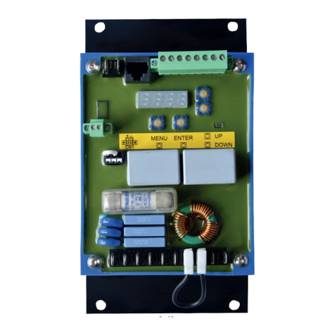
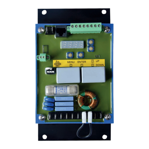
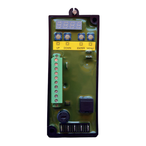
Beltrame S2007 User manual


MANUALE S2007 PRELIMINARE.DOC
PAG.2/21
Contents
Contents ..................................................................................................... 2
Important Notice ........................................................................................ 3
1. SAFETY INSTRUCTIONS ...................................................................... 4
1.1 General .................................................................................................... 4
1.2 Safety Instructions..................................................................................... 5
2. DEVICE DESCRIPTION ........................................................................ 6
2.1 Introduction .............................................................................................. 6
2.2 Hardware.................................................................................................. 6
2.2.1 Control elements and interfaces .......................................................... 7
2.2.2 Device connections CN3 ..................................................................... 9
2.2.3 Device connections CN5 ................................................................... 10
2.2.4 Device connections CN2 ................................................................... 10
2.2.5 Device connections CN4 ................................................................... 11
3. OPERATOR INTERFACE ..................................................................... 12
3.1 Set or change parameters......................................................................... 12
3.2 Navigating the menus .............................................................................. 13
3.3 Menu...................................................................................................... 14
3.3.1 Menu d - Display ............................................................................. 14
3.3.2 Menu P - Parameters........................................................................ 14
4. Running the engine........................................................................... 16
4.1 Running the engine .................................................................................. 16
4.1.1 Starting the engine .......................................................................... 16
4.1.2 Governor Performance ..................................................................... 16
4.2 Additional features................................................................................... 17
4.2.1 Real-Time Display............................................................................ 17
4.2.2 Idle Speed ...................................................................................... 17
4.2.3 Speed Droop Operation .................................................................... 17
4.2.4 Overspeed ...................................................................................... 17
4.2.5 Loss of Magnetic Pickup Sensing........................................................ 18
4.2.6 Variable Speed Inputs ...................................................................... 18
5. System troubleshooting .................................................................... 19
5.1 System inoperative .................................................................................. 19
5.2 Insufficient Magnetic Speed Signal ............................................................. 19
5.3 Electromagnetic Compatibility (EMC)................................................................ 19
5.4 Instability ................................................................................................. 20
6. Specifications ................................................................................... 21
6.1 Performance............................................................................................ 21
6.2 Enviromental........................................................................................... 21
6.3 Compliance/ standards ............................................................................. 21
6.4 Input/output ........................................................................................... 21
6.5 Reliability ............................................................................................... 21
6.6 Physical .................................................................................................. 21

MANUALE S2007 PRELIMINARE.DOC
PAG.3/21
Important Notice
Our experience has shown that, if the information and recommendations contained
in this Operating Instructions are observed, the best possible reliability of our
products is assured.
The data contained herein purports solely to describe the product and is not a
warranty of performance or characteristics. It is with the best interests of our
customers in mind that we constantly strive to improve our products and keep them
abreast of advances in technology. This may, however, lead to discrepancies
between a product and its "Technical Description" or " Operating Instructions".
This document has been carefully prepared and reviewed, however should in spite of
this the reader find an error, he is requested to inform us at his earliest convenience.
It is scarcely possible for the operating instructions for technical equipment to cover
every eventuality, which can occur in practice. We would therefore request you to
notify us or our agent in the case of all unusual behaviour that does not appear to be
covered by these operating instructions.
It is pointed out that all local regulations must be observed when connecting and
commissioning this equipment in addition to these operating instructions.
We cannot accept any responsibility for damage incurred as a result of mishandling
the equipment regardless of whether particular reference is made in these operating
instructions or not.
We lay particular stress on the fact that only genuine spare parts should be used for
replacements.
All rights with respect to this document, including applications for patent and
registration of other industrial property rights, are reserved. Unauthorized use, in
particular reproduction or making available to third parties, is prohibited.
Manufacturer’s address

MANUALE S2007 PRELIMINARE.DOC
PAG.4/21
1. SAFETY INSTRUCTIONS
1.1 General
The safety instructions shall be followed during installation, commissioning, operation and
maintenance. Read all instructions carefully before operating the device and keep this
manual for future reference.
Required Qualification
Personnel involved in installation work and commissioning of the S2007 must be
familiar, specially instructed and informed about the residual danger areas according
to the regulations currently in force.
Operating personnel is not permitted to work at the control system.
Specially instructed personnel must only carry out maintenance and repair work.
The maintenance personnel must be informed about the emergency shutdown
measures and must be capable of turning off the system in case of emergency.
The maintenance personnel must be familiar with the accident prevention measures
at their workplace and must be instructed in first aid and fire fighting.
It is the owner’s responsibility to ensure that each person involved in the installation
and commissioning of the S2007 has received the appropriate training or instructions
and has thoroughly read and clearly understood the safety instructions in this
chapter.

MANUALE S2007 PRELIMINARE.DOC
PAG.5/21
1.2 Safety Instructions
The safety instructions always appear at the beginning of each chapter and/or
precede any instruction in the context where a potentially dangerous situation may
appear. The safety instructions are divided into five categories and emphasized by
the use of the following layout and safety signs:
DANGER!
This symbol indicates an imminent danger resulting from
mechanical forces or high voltage. A non-observance leads to
life-threatening physical injury or death.
WARNING!
This symbol indicates a dangerous situation. A non-observance
may lead to bad or life-threatening physical injury or death.
CAUTION!
This symbol indicates a dangerous situation. A non-observance
may lead to physical injury or cause damage to the device.
NOTICE!
This symbol emphasizes important information. A non-
observance may cause damage to the device or to objects close
to it.
IMPORTANT!
This symbol indicates useful information. Not to be used to
indicate dangerous situations.

MANUALE S2007 PRELIMINARE.DOC
PAG.6/21
2. DEVICE DESCRIPTION
2.1 Introduction
The S2007 is an electronic device designed to control engine speed with fast and
precise response to transient load changes.
This closed loop control, when connected to a proportional electric actuator and
supplied with a magnetic speed sensor signal, will control a wide variety of engines in
an isochronous or droop mode.
It is designed for high reliability and built ruggedly to withstand the engine
environment.
A practical and simple-to-operate panel on the unit is used for all control operations.
In addition, user-friendly software facilitates commissioning and allows optimization
of operation.
The mechanical construction is compact and robust.
2.2 Hardware
Structure:
The device, placed inside a plastic box, is submerged in resin allowing so the
maximum resistance against engine vibrations and a reliability with time.
Control elements:
A 4 digit 7-segment display is located on it in order to allow an easy visualization of
parameters. The use of push buttons placed at the side and below the display allows
to scroll the menu of all parameters and to set those of interest.
Installation:
Mounting:
The S2007 is designed for wall mounting on a metal panel.
Mounting on a non-dissipative surface such as a plastic panel may lead to device
overheating and is to be avoided.
For optimal cooling is to keep free a minimum distance of 100 mm all around the
unit.
Connection diagram:
Basic electrical connections are illustrated in the figure below.

MANUALE S2007 PRELIMINARE.DOC
PAG.7/21
2.2.1 Control elements and interfaces
Carrying out settings on the unit
The display and the four keys are sufficient to allow complete operation.
All settings can be carried out directly on the unit without additional equipment
Input/Output configuration
Parameter setting
Display of main measures.

MANUALE S2007 PRELIMINARE.DOC
PAG.8/21
Terminal blocks
Overview of full device connections
CN2 –CAN BUS interface
1. CAN H
2. CAN L
3. GND CAN
4. n.c.
5. n.c.
6. n.c.
7. GND CAN
8. n.c.
CN3 –Inputs/Outputs
1. Actuator -
2. Actuator +
3. Battery –(GND/COM)
CN4 –RS232 interface
1. Reserved (do NOT use!)
2. Tx
3. Rx
4. Reserved (do NOT use!)
5. GND
6. Reserved (do NOT use!)
7. Reserved (do NOT use!)
8. Reserved (do NOT use!)
9. Reserved (do NOT use!)
CN5 –Inputs/Outputs
1. Digital input (COM=GND)
2. Digital input (COM=GND)

MANUALE S2007 PRELIMINARE.DOC
PAG.9/21
4. Battery + (12÷24Vdc)
5. Out aux (Solenoid valve)
6. Pickup +
7. Pickup –
8. UP (COM=GND)
9. DOWN (COM=GND)
10. IDLE (COM=GND)
3. GND/COM
4. Analog input 0÷10V
5. Supply output +10V (max 20mA)
6. Analog input 4÷20mA
7. Analog input -5÷5V
8. GND/COM
n.c. = not connected
2.2.2 Device connections CN3
Terminal designation
Signal
Specifications
Actuator
DC output
12÷24Vdc
0÷12 A (15A for 10s)
Solenoid valve
Digital output
12÷24Vdc
2Amax
Pickup
Passive pickup
Active pickup
or
Up
Digital Input
Down
Digital Input
IDLE
Digital Input

MANUALE S2007 PRELIMINARE.DOC
PAG.10/21
2.2.3 Device connections CN5
Terminal designation
Signal
Specifications
Digital inputs
2 digital inputs
programmable function
Analog inputs
analog input
0÷10Vdc
(Potentiometer
=2k÷ 5k
0,25W)
analog input
4÷20mA
analog input
-5V ÷ +5V
2.2.4 Device connections CN2
Terminal designation
Signal
Specifications
Communication
CAN
selectable termination

MANUALE S2007 PRELIMINARE.DOC
PAG.11/21
CANopen and proprietary
protocols
2.2.5 Device connections CN4
Terminal designation
Signal
Specifications
Communication
RS232
NOTICE!
To connect a device such as a notebook or a personal computer to S2007
Speed Digital Governor,proprietary USB/RS232 adapter or proprietary
RS232/RS232 adapter shall be

MANUALE S2007 PRELIMINARE.DOC
PAG.12/21
3. OPERATOR INTERFACE
In this following charter are described the operations of management parameter
using the integrated display.
3.1 Set or change parameters
Many parameter can be accessed using the integrated display and keys.
SCROL Change menu parameter set (d.xxx and P.xxx)
ENTER Select or save current displayed parameter
UP Increase parameter number or value
DOWN Decrease parameter number or value

MANUALE S2007 PRELIMINARE.DOC
PAG.13/21
3.2 Navigating the menus
When the S2007 is power on, the display automatically shows parameter d.000 (Engine
speed) in the Display menu.
Example: how to change a SPEED reference

MANUALE S2007 PRELIMINARE.DOC
PAG.14/21
3.3 Menu
3.3.1 Menu d - Display
Display
Name
Description
[Units]
D.000
Engine speed
Actual engine speed
rpm
D.001
Speed set
Speed set point
rpm
D.002
Actuator current
Current supplied to actuator
A
D.003
Actuator voltage
Voltage supplied to actuator
V
D.004
Input 0-10V
0-10V analog input voltage
V
D.005
Input 4-20mA
4-20mA analog input current
mA
D.006
V Batt
Battery voltage
V
D.007
Firmware version
3.3.2 Menu P - Parameters
Parameter
Name
Description
[Units]
Default
Range
P.000
Speed
Engine speed Set Point
Rpm
1500
1200 - 4000
P.001
Kp
(GAIN)
Proportional (P) gain for
PID control loop
20 - 5000
P.002
Ki
(STABILITY)
Integral (I) gain for PID
control loop
0 - 5000
P.003
Kd
(DEADTIME)
Derivative (D)gain for PID
control loop
0 - 5000
P.004
IDLE
Engine speed in Idle mode
Rpm
1300
1000 - 4000
P.005
Crank
Crank termination
threshold: RPM when the
governor changes from
crank mode to control
mode
Rpm
1200
1000 - 4000
P.006
Over speed
Over speed: RPM when
actuator is shut off for
safety reason
Rpm
1700
1350 - 4750
P.007
Start fuel
Starting fuel: preset utput
voltage to actuator when
crank begins
100%
0,5% - 100%
P.008
Speed ramp
Rate throttle at which is
ramped open during start
10%
0-100%
P.009
Droop
Droop at maximun load
current (based on duty
cycle of the actuator)
1,5 %
0,1% - 8%
P.010
Max current
Max actuator current
A
10
1 - 15
P.011
Overload time
Time before current is
clamped to Max value
(P.010)
10s
0,5s –60s
P.012
Variable speed
control
Maximum speed change
from analog inputs
3%
0% - 100%
P.013
Teeth
Number of teeth on
flywheel
60
10 - 1000

MANUALE S2007 PRELIMINARE.DOC
PAG.15/21
P.014
Rate
Time between calls to PID
control loop
20
1 - 200
P.015
Reset
To reset the device, enter
the number “333” in
parameter P.015

MANUALE S2007 PRELIMINARE.DOC
PAG.16/21
4. RUNNING THE ENGINE
4.1 Running the engine
4.1.1 Starting the engine
Before cranking engine, supply DC power to governor system, then actuator will be pre-set as
defined by START FUEL parameter (P.007, default value is maximum fuel rate).
Starting Ramp (P.007), will then control the rate at which fuel is increased during engine
cranking.
NOTICE!
if engine speed is unstable after start up, adjust GAIN (P.001),
STABILITY (P.002), and DEADTIME COMPENSATION (P.003) until
engine speed is stabilized.
Poor PID settings can affect this response so tune the system at
normal operating speeds before setting the starting parameters (see
below).
4.1.2 Governor Performance
Once the engine is at operating speed and at no load, the following governor performance
adjustment can be made.
A. Increase GAIN parameter until motor speed reachs instability. Gradually decrease the
Gain until stability is recovered. Decrease one count further to insure stable
performance.
B. Increase STABILITY parameter until motor speed reachs instability. Gradually
decrease Stability until stability is recovered. Decrease one count further to insure
stable performance.
C. Increase DEADTIME parameter until motor speed reachs instability. Gradually
decrease Deadtime until stability is recovered. Decrease one count further to insure
stable performance.
D. GAIN, STABILITY and DEADTIME small adjustments may be required after load is
applied to engine. Normally, adjustments made in no load conditions achieve
satisfactory performance.

MANUALE S2007 PRELIMINARE.DOC
PAG.17/21
4.2 Additional features
4.2.1 Real-Time Display
While engine runs, S2007 Digital Speed Governor can display real time measures and other
useful information (see table below). Cycle through the table with UP / DOWN keys.
Display
Parametet
Description
Units
D.000
Engine speed
Actual engine speed
rpm
D.001
Speed set
Speed set point
rpm
D.002
Actuator current
Actual actuator current
A
D.003
Actuator voltage
Actual actuator voltage
V
D.004
Input 0-10V
0-10V input voltage
V
D.005
Input 4-20mA
4-20mA input current
mA
D.006
V Batt
Battery voltage
V
D.007
Firmware version
4.2.2 Idle Speed
To adjust IDLE speed, shut down engine,
place optional external switch in IDLE position
then restart engine. Once started, IDLE speed
set point can be calibrated through IDLE
parameter (P.004).
4.2.3 Speed Droop Operation
Droop is typically used with parallel of several engine driven generators.
With S2007 governor powered off,
place optional external selector
switch in DROOP position, then start
engine. While engine is running,
DROOP can be adjusted by DROOP
parameter (P.007). In DROOP MODE
engine speed will decrease as engine
load increases. The percentage of
droop is based on the change in
current in the actuator from no load
to full load (DRNG in the Special
Menu).
4.2.4 Overspeed
When the S2007 detects engine has reached the
speed specified by the OVERSPEED parameter
(P.006), the S2007 will force the speed to 0
RPM, will set the actuator output to 0V and, if
enabled, open the solenoid valve. OVERSPEED
is a Menu parameter, and is expressed in RPM.
Notice!
If incorrect tooth count is entered
the OverSpeed setting may not be
what is desired so never rely on
this function as the ultimate
equipment protection.

MANUALE S2007 PRELIMINARE.DOC
PAG.18/21
If the running speed of the engine reaches the OVERSPEED set point, while the
system is in a running state, the S2007 will stop outputting a signal to the actuator
for a zero fuel command and will no longer attempt to control the engine.
After the S2007 has detected an overspeed, the display will flash
the RPM along with the warning and OVERSPEED indicators. No
parameters will be allowed to be changed.
To re-activate the S2007, DC power must be turned off then back
on to reset the control.
4.2.5 Loss of Magnetic Pickup Sensing
If the S2007 is commanding the actuator to move and detects no input from the
magnetic pickup, the S2007 will set the actuator to 0V and command the speed to 0
RPM.
After the S2007 has detected loss of magnetic pickup, the display
will flash the RPM along with the warning indicator.
No parameters will be allowed to be changed.
4.2.6 Variable Speed Inputs
The S2007 is equipped with four inputs for variable speed.
1. analog input 0÷10V. This input accepts a 2÷5K potentiometer connected between
terminals 3,4 and 5 of CN5.
2. analog input 4÷20mA. The terminals used are 6 and 8 of CN5.
3. analog input -5V ÷ +5V. The terminals used are 7 and 8 of CN5.
4. digital inputs: terminal 8 for UP and terminal 9 for DOWN of CN3 (closed to ground).
Generally, these inputs are used to perform fine tuning of generator frequency or in
conjunction with other governor system accessories such as load sharing units,
synchronizers, etc. Variable speed function is used to operate over a larger RPM range.

MANUALE S2007 PRELIMINARE.DOC
PAG.19/21
5. SYSTEM TROUBLESHOOTING
5.1 System inoperative
If the engine governing system does not function, the fault may be determined by performing
the voltage tests described in Steps 1 through 3. Positive (+) and negative (-) refer to meter
polarity. Should normal values be indicated during troubleshooting steps, then the fault may
be with the actuator or the wiring to the actuator. Tests are performed with battery power on
and the engine off, except where noted. See actuator publication for testing procedure on the
actuator.
Step
Wires
Normal reading
Probable cause of abnormal reading
1
CN3-3 Battery –(GND)
CN3-4 Battery +
Battery supply voltage
(12 or 24V dc)
1. DC battery power not connected. Check
for blown fuse
2. Low battery voltage
3. Wiring error
2
CN3-6
CN3-7
1Vac RMS minimum
while cranking
1. Gap between speed sensor and gear
teeth too great Check gap
2. Improper or defective wiring to the speed
sensor
3. Resistance between 6 and 7 (CN3) should
be 30 to 1200 ohms. See specific
magnetic pickup data for resistance
4. Defective speed sensor.
5.2 Insufficient Magnetic Speed Signal
A strong magnetic speed sensor signal will eliminate the possibility of missed or extra pulses.
A speed sensor signal of 1VAC RMS or greater at cranking speed is required. Measure the
signal at Terminals 6 and 7 (CN3). Shielding of the pickup wires is recommended.
The amplitude of the speed sensor signal can be raised by reducing the gap between the
speed sensor tip and the engine ring gear. The gap should not be any smaller than 0,45 mm.
When the engine is stopped, back the speed sensor out by 3/4 turn after touching the ring
gear tooth to achieve a satisfactory air gap.
5.3 Electromagnetic Compatibility (EMC)
EMI SUSCEPTIBILITY - The governor system is rated for CE levels per EN50082-1 and
EN50082-2. However, it can be adversely affected by large interfering signals that are
conducted through the cabling or through direct radiation into the control circuits.
Although regulation of emitting devices is better controlled today it is still difficult to predict
levels of interference, applications that include magnetos, solid sate ignition systems, radio
transmitters, voltage regulators or battery chargers and they should be considered as suspect
as possible interfering sources. If it is suspected that external fields, either those that are
radiated or conducted, are or will affect the governor systems operation, it is recommended
to use shielded cable for all external connections to the control Terminals. Be sure that only
one end of the shields, including the speed sensor shield, is connected to a single point on
the case of the speed control unit. Mount the speed control to a grounded metal back plate or
place it in a sealed metal box.
Radiation is when the interfering signal is radiated directly through space to the governing
system. A metal shield or a solid metal container is usually effective for this interference.
Conduction is when the interfering signal is conducted through the interconnecting wiring.
Shielded cables and installing filters are common remedies.

MANUALE S2007 PRELIMINARE.DOC
PAG.20/21
5.4 Instability
Instability in a closed loop speed control system can be categorized into two general types.
PERIODIC appears to be sinusoidal and at a regular rate. NON-PERIODIC is a random
wandering or an occasional deviation from a steady state band for no apparent reason.
The PERIODIC type can be further classified as fast or slow instability. Fast instability is a 3
Hz. or faster irregularity of the speed and is usually a jitter. Slow periodic instability is below
3 Hz., can be very slow, and is sometimes violent.
If fast instability occurs, this is typically the governor responding to engine firings. Raising
the engine speed increases the frequency of instability and vice versa. In this case, readjust
the GAIN and STABILITY for optimum control. In extreme cases, this may not take all the
jitter out of the system. In this case, decrease the DEADTIME parameter.
Slow instability can have many causes. If slow instability exists, verify the SOFT Special
Menu parameter is disabled. If this is unsuccessful, it is possible to decrease the update rate
of the controller. This is done by decreasing the RATE Advanced parameter. This should be
done with extreme caution and in single increments. Each time RATE is changed, the
GAIN, STABILITY, and DEADTIME must be re-adjusted.
If slow instability is unaffected by this procedure, evaluate the fuel system and engine
performance. Check the fuel system linkage for binding, high friction, or poor linkage is the
moist likely cause. Be sure to check linkage during engine operation. Also look at the engine
fuel system. Irregularities with carburetion or fuel injection systems can change engine power
with a constant throttle setting. This can result in speed deviations beyond the control of the
governor system. Adding a small amount of droop can help stabilize the system for
troubleshooting purposes.
NON-PERIODIC instability should respond to the GAIN control. If increasing the Gain
reduces the instability, then the problem is probably with the engine. Higher gain allows the
governor to respond faster and try to correct for disturbance. Look for engine mis-firings, an
erratic fuel system, or load changes on the engine generator set voltage regulator.
If unsuccessful in solving instability, contact Beltrame CSE for assistance.
Other manuals for S2007
1
Table of contents
Other Beltrame Controllers manuals
Popular Controllers manuals by other brands
iNels
iNels RFWB-20/G quick start guide
Marshall Excelsior
Marshall Excelsior MEGR-167CH/751 instruction manual
Moons'
Moons' LIN ENGINEERING Silverpak 17C user manual

Ascon tecnologic
Ascon tecnologic TLZ35 operating instructions
Rockwell Automation
Rockwell Automation Allen-Bradley 1512A user manual
ZyXEL Communications
ZyXEL Communications Network Device NXC-8160s quick start guide
