Bench Dog Tools Pro-Builder Series User manual
Read and understand the entire contents
of this manual before attempting assembly
or operation of this tool! Inspect contents
for shipping damage and shortages. Report
problems directly to Bench Dog, Inc.
Be sure to check out our web site for all the
latest and greatest accessories and tools.
www.benchdog.com
1-800-786-8902
QUESTIONS? Tools Required
1/8" hex wrench (supplied)
5/32" hex wrench (supplied)
3/16" hex wrench (supplied)
7/16" wrench
7/16" socket wrench
Phillips screwdriver
Thank you for purchasing our ProTop
Contractor router table! We are certain this
made in USA router table, with its many
exclusive features, will become one of your
favorite tools.
Bench Dog offers a full line of tools and
accessories that continue Bench Dog's
commitment to solve common problems
and ensure safe operation of a variety of
woodworking and other tools.
If you have questions, please feel free to
contact us at any time. Your comments are
always welcome.
612.782.8205 main
612.788.2518 fax
800.786.8902 toll free
benchdog.com
Bench Dog, Inc.
3310 5th St. NE
Minneapolis, MN 55418
82-0036-08 1204
2004 Bench Dog, Inc.
Stock No. 40-001
Keep this manual handy for
quick reference
Owner's Manual

LIMITED TWO-YEAR WARRANTY
We make every effort to assure that our products meet quality and durability standards, and warrant to the original retail purchaser that this
product is free from defects in materials and workmanship for two years. Remedy shall be limited to Bench Dog’s choice of repair,
replacement or refund. This warranty does not provide remedy for consequential economic loss.
This is a limited two year warranty. It requires the purchaser to contact Bench Dog in writing within 30 days of discovering the defect.
Warranty does not apply to defects due directly or indirectly to misuse, abuse, negligence or accidents, repairs or alterations, or due to lack
of maintenance. It excludes components and parts not manufactured by Bench Dog, defects caused by failure to provide a suitable
installation environment, and damage caused by use for purposes other than those for which the product was designed. Bench Dog, Inc.
reserves the right to make product changes without notice and without obligation to make these changes on products previously sold. It
excludes warranties of fitness for a particular purpose.
If the product is defective, we reserve the right to fix it, replace it, or refund the cost of the product to you. Typically, this results in a refund.
All claims are limited to the two-year claims period. We must receive the product before a credit or refund will be issued. The warranty
language on the product or in the product’s manual may contain additional limitations, which govern.
If you wish to return something, call the dealer where you purchased the product. If you wish to return something purchased from Bench
Dog directly, call 1-800-786-8902 to receive an RMA number. Upon receipt and inspection of the goods, a credit or replacement will be
issued for defective products. Return of nondefective items to Bench Dog are subject to a 7% restocking charge. This is necessary due to
the cost of checking, repackaging, and inventorying the stock.
BENCH DOG DISCLAIMS AND BUYER EXPRESSLY WAIVES ANY AND ALL WARRANTIES, EXPRESS OR IMPLIED, INCLUDING BUT
NOT LIMITED TO, IMPLIED CONDITIONS OF FITNESS FOR A PARTICULAR PURPOSE, MERCHANTABILITY, OR ANY OTHER
MATTER.
Page 2
General Conditions / Limited Two Year Warranty
Important Safety Points
Before operating your router table please read this manual thoroughly. Safety and use tips are contained in the manual.
This page is not the sole source of safety information. Retain the manual for future reference. Refer to your router
owner's manual for safety instructions regarding use of that tool. This manual is not an instruction book on how to do
woodworking with a power tool. We encourage all woodworkers to continually seek improvement in their woodworking skills,
regardless of their craftsmanship or years of experience. The router table, fence and accessories must only be used for their
intended purpose: woodworking via normal routing operations. “Normal operations” means basic shaping of wood in
conditions where grounded electricity, sharp tools, dust, and rapidly spinning parts can be used or encountered safely. The
following instructions elaborate on this concept.
1. Do not use your router table as a step or seat.
2. The top and cabinet must be properly secured, and be level before use. Inspect your table and base for
damage and levelness prior to each use.
3. Keep work area clean, dry and well lit.
4. The hardware affixing the insert to the routertop must be installed for safe use. Tighten insert hold-down
screws before each use.
5. Safe operation requires a router table fence, bit guard, dust collection system, starting pin or fulcrum, and
speed reducer for large diameter bits. We recommend reducing router speed for 1" or larger diameter bits.
Consult your bit manufacturer for the exact speed.
6. Use the right tool for the job. Do not force a tool or attachment to do a job for which it was not designed.
7. Secure your work with a featherboard, clamps, or a vice when appropriate. The use of inappropriate
accessories may cause injury.
8. Wear safety glasses, dust mask, face shield and ear protection. This is not an exhaustive list. Every-day
eye glasses do not substitute for safety glasses.
9. Do not wear gloves or jewelry while using a power tool and ProTop Contractor.
10. Maintain your equipment and its accessories in good working condition. Look for wear, poor alignment of
moving parts, binding of moving parts, breakage, poor mounting, or other conditions that may affect
operation and safety. Repair or replace any damaged parts.
11. Disconnect the power before moving, adjusting, or repairing parts, or otherwise maintaining your router table
and any accessories you may be using.
12. Keep children, pets, and those who may disregard safety away from work area, cords, sockets and tools.
13. Wear snug fitting clothes and keep long hair back to avoid catching in moving parts.
14. Do not overreach. Maintain balanced footing and stance.
15. Stay alert. Use common sense.

Page 3
1
5
4
6
10
11 11
13
12
15 14
18
16 17
19
89
2
3
7
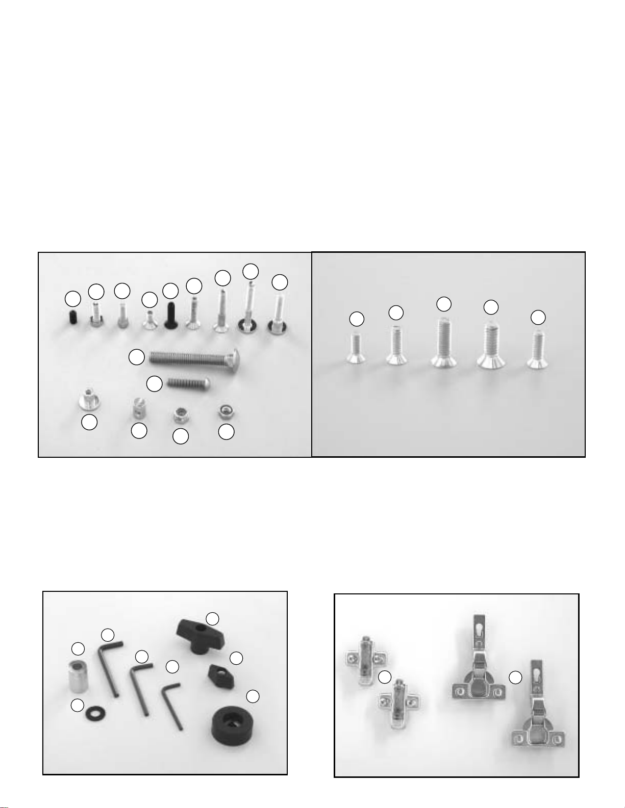
Contents of Box
Fence Hardware/Accessories
Cabinet Panels
Item Quantity Part Number Description
1 1 FP0100-01 Router top
2 1 FP0100-02 Base panel
3 1 FP0100-03 Door
4 1 FP0100-04 Side panel, left
5 1 FP0100-05 Side panel, right
6 1 FP0100-06 Back panel
7 1 FP0133 Router insert plate (Stock No. 40-042)
8 2 DECALS Decals, side panel (not shown)
Item Quantity Part Number Description
8 1 FP0054 Bit guard
9 1 FP0059 Dust port
10 1 R0001 Aluminum fence
11 2 FP0053 Subfences
12 2 R0009 Jointer bars
13 1 R0049 Miter track, 24"
14 1 FP0106 Insert bracket, right
15 1 FP0105 Insert bracket, left
16 1 150-0020-01 Hardware bag # 1
17 1 150-0020-02 Hardware bag # 2
18 1 150-0001-03 Hardware bag # 3
19 1 150-0020-03 Hardware bag # 4
43
42
47
46 45
40
41
44
38 35 37 36 39
Contents of bag #1
Contents
of Box
Hardware bag #1
Item Quantity Part Number Description
20 2 H0168 Bolt, 3/8-16 x 2-3/4" Carriage
21 6 H0004 Bolt, 1/4-20 x 3/4" Hex head
22 4 H0006 Bolt, 1/4-20 x 50mm (2") Round head
23 4 H0005 Bolt, 1/4-20 x 40mm (1-1/2") Round head shoulder
24 4 H0173 Cap screw, 1/4-20 x 1-1/4" Button head socket
25 18 H0017 Cross Dowel, 1/4-20
26 10 H0103 Nut, 1/4-20 Nylon insert lock
27 8 H0031 Nut, 1/4-20 Hex
28 4 H0174 T-Nut, 1/4-20
29 2 H0171 Screw, 1/4-20 x 5/8" Flat head socket cap
30 6 H0169 Screw, 1/4-20 x 1-1/4" Flat head socket cap
31 12 H0170 Screw, 1/4-20 x 1-3/4" Flat head socket cap
32 11 H0050 Screw, 1/4-28 x 1/2" Set-socket
33 8 H0172 Screw, 1/4-20 x 3/4" Socket head cap
34 2 H0045 Screw, 1/4-20 x 1" Flat head Phillips (black)
35 3 H0037 Screw, 10-24 x 5/8" Flat head Phillips
36 3 H0057 Screw, 5/16-18 x 3/4", Flat head Phillips
37 3 H0060 Screw, 6 x 20 mm, Flat head Phillips
38 3 H0163 Screw, 8-32 x 1/2", Flat head Phillips
39 3 H0198 Screw, 10-32 x 5/8", Flat head Phillips
Hardware bag #2
Contents of bag #2
Item Quantity Part Number Description
40 2 H0014 T-Knob, 3/8-16 x 2"
41 6 H0012 T-Knob, 1/4-20 x 1-1/8"
42 2 H0067 Washer, 3/8" Nylon
43 2 R0010 Spacer, Alum. Knob
44 4 H0175 Rubber feet
45 1 H0019 Wrench, 1/8" hex
46 1 H0128 Wrench, 5/32" hex
47 1 H0129 Wrench, 3/16" hex
Hardware bag #3 (Hinges)
Item Quantity Part Number Description
48 2 H0023 Mounting plate, hinge
49 2 H0027 Hinge, self closing Euro style
32 21 33 29 34 30 31 22 23
20
24
28 25 26 27
Contents of bag #1
(Router insert plate mounting screws)
48 49
Contents of bag #3
Page 4
1/4-20
cross dowel
1/4-20 x 2"
round head bolt
Page 5
Assembly Instructions
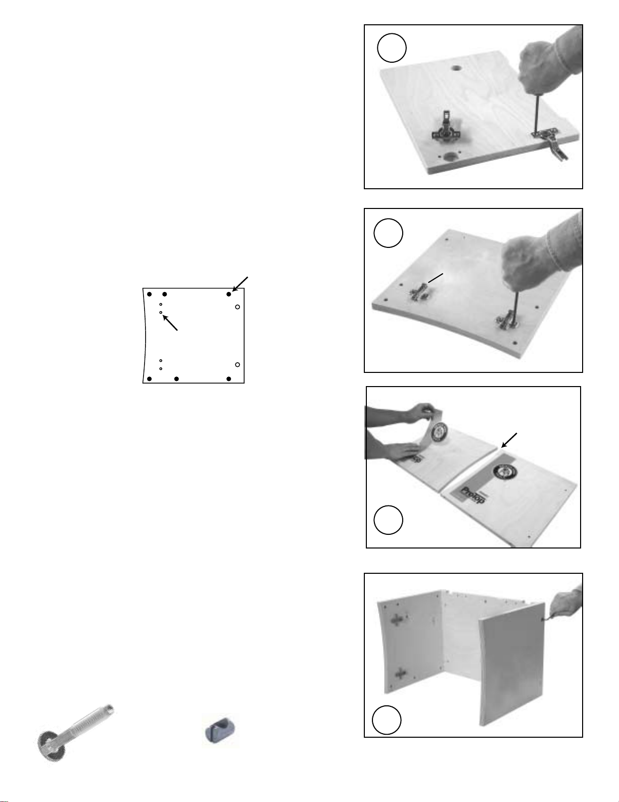
1. Attach the (2) hinges to the door.
Press the hinge "cups" into the large bore in the door. With a
Phillips screwdriver tighten the integral hinge cams clockwise
approximately 1/4 turn. Do not over tighten the cams.
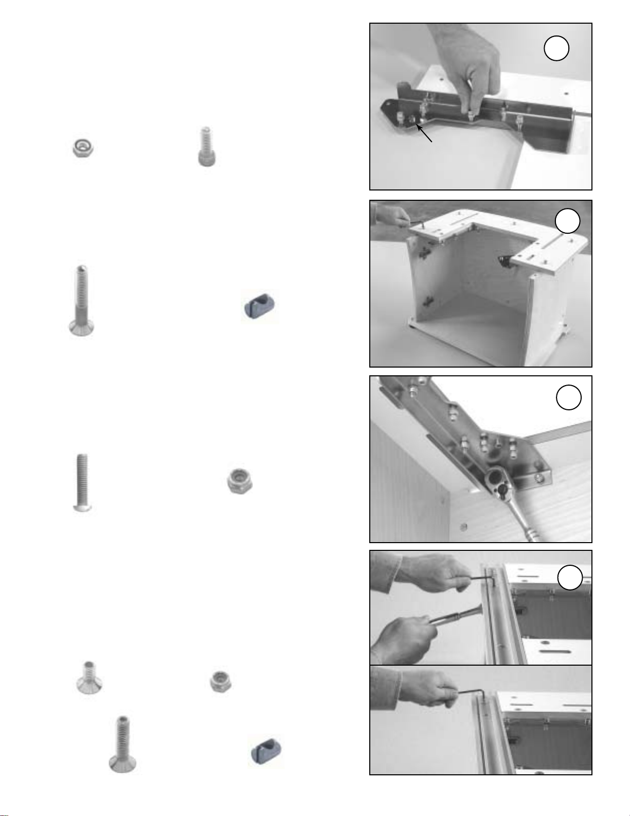
3. Attach side panels to the back panel.
The back panel has two notches that identify the top of the panel,
as shown. The left panel has the hinges. Align the two holes in
side panels with the corresponding holes in the back panel. Use
1/4-20 x 2" round head bolts and 1/4-20 cross dowels. The cross
dowels go in the back panel. Tighten with the included 5/32" hex
wrench. Repeat this step for the right panel. Do not fully tighten the
bolts at this time.
Note: Check that the cross dowel holes are free of debris
prior to inserting the cross dowels.
1
3
2a. Attach the (2) hinge mounting plates to the left side panel.
Carefully study the orientation in Fig. 2. The hinge mounting plates
resemble a cross. Locate the top of the cross nearest the curved
front edge of the left side panel, as shown. On the bottom of the
cross you will find the hinge release lever. All cross dowel holes
are located inside the cabinet.
2a
hinge
plate holes
cross dowel
holes
hinge release
lever here!
2b. Attach the (2) decals to the side panels.
The decals go on the outside of the left and right side panels. The
right side panel decal is positioned near the front curved edge, as
shown. In this photo the person is installing the decal on the left
side panel, about two inches from the back edge. If you find it
easier, attach the decals AFTER your router table is fully
assembled.
right panel
front is curved
on both panels
front edge is curved
on both side panels
left panel
top
LEFT
SIDE PANEL
TOP
CURVED
FRONT EDGE
CROSS DOWEL HOLES ARE
LOCATED INSIDE THE CABINET! 2b
Page 6
4. Attach the (4) rubber feet to base panel.
Insert the "T" nuts into the four large holes in the base panel.
Locate the head of the "T" nut on the top side of the base panel.
The bottom of the base panel has countersinks, the top does not.
Insert a 1/4-20 x 3/4" hex head bolt through the rubber feet, and
thread into "T" nut, as shown. Tighten using the 3/16" hex wrench
and a 7/16" socket. Do not overtighten.
4
5. Attach base panel to cabinet assembly.
Flip the cabinet assembly upside down, as shown. Use the 1/4-
20 x 1-3/4" flat head socket cap screws and 1/4-20 cross dowels.
Tighten securely. Flip the cabinet assembly right side up when
done.
5
6. Attach insert brackets to routertop.
Position insert brackets as shown. Be sure to mount the brackets
to the underside of the routertop. The routertop surface has
countersinks, the underside does not. Do not fully tighten the
bolts.
6
The bottom side of the base panel has countersunk
holes to accept other fasteners.
T-nut
1/4-20 x 1-3/4"
flat head socket
cap screw
1/4-20 x 3/4"
hex head bolt rubber
foot
1/4-20 x 1-1/4"
flat head socket
cap screw
nylon insert
lock nut
1/4-20
cross dowel
Page 7
7. Install the (8) leveling screws.
Fully thread a 1/4" hex nut on each of the (8) 1/4-20 x 3/4" socket
head cap screws. Install these bolt assemblies into the (8)
leveling holes in the insert brackets. DO NOT use the two insert
plate attachment holes. These holes have protruding round nuts
on the underside of the insert brackets. You will adjust these
leveling screws in step 13.
8. Attach routertop to cabinet asssembly.
Attach using 1/4-20 x 1-3/4" flat head socket cap screws and
1/4-20 cross dowels. Do not fully tighten at this time.
9. Connect insert brackets to the back panel.
Attach using 1/4-20 x 1-1/4" button head screws and 1/4" nylon
insert lock nuts, as shown. Locate the nuts to the inside of the
cabinet. Do not fully tighten at this time.
10. Attach the miter track to routertop.
Use (2) 1/4-20 x 5/8" flat head socket cap screws and 1/4" nylon
insert lock nuts to fasten the miter track to the insert brackets.
Use (2) 1/4-20 x 1-1/4" flat head socket cap screws and 1/4-20
cross dowels to fasten the miter track to the cabinet side panels.
Eliminate any gap between the miter track and routertop before
tightening the bolts.
7
8
9
10
1/4"
hex nut
1/4-20 x 3/4"
socket head
cap screw
1/4-20 x 1-3/4"
flat head socket
cap screw
1/4-20 x 1-1/4"
button head
socket cap screw
1/4-20 x 5/8"
flat head socket
cap screws
1/4-20
cross dowel
nylon insert
lock nut
nylon insert
lock nut
1/4-20
cross dowel
1/4-20 x 1-1/4"
flat head socket
cap screws.
insert plate
attachment
hole
Page 8
11. Fully tighten all bolts and screws.
Correct any misalignments at this time.
13. Adjust leveling screws until insert plate is flush.
Install the insert plate into the routertop. Adjust leveling screws
until the plate is flush with routertop. To tighten, hold the socket
head cap screw with the 3/16" hex wrench, and use your 7/16"
open end wrench to tighten the nuts, as shown. Note: it may be
necessary to fine tune the adjustment after installing router.
11
12. Adjust miter gauge track to fit your miter gauge.
First test fit your miter gauge into the track. If it's too tight,
squeeze the gib against the front wall of the miter track with a
pair of Channel Locks, use a shop towel to prevent marring.
Next, install the (11) 1/4-28 x 1/2" set screws. Tightening the
screws will deflect the gib into your miter gauge. Tighten all
screws uniformly and gradually until the desired fit is achieved.
12
13
1/4-28 x 1/2"
set screw
This miter track ONLY fits standard 3/8" x 3/4" miter
gauge bars. Wax the slot and bar to reduce wear.
*Miter Gauge NOT INCLUDED!
front
wall gib
Page 9
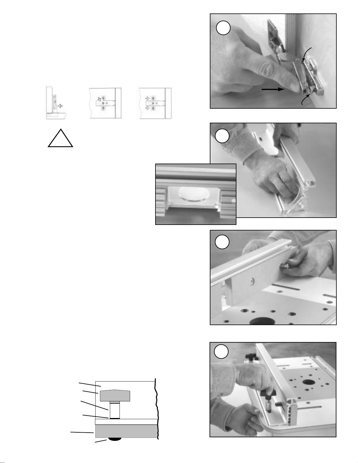
14. Attach door.
Clip on door by "hooking" front of hinge onto hinge mounting
plate first. Then push on back edge of hinge until it locks into
place. If door does not clip on, check hinge mounting plates for
proper installation. To remove door, push down on release
levers.
15. Install dust port.
Pull the dust port along the two 45º
grooves in the back of the fence until it
snaps into place (at the center of the open
area). The dust port fits tightly.
16. Install the (2) MDF subfences onto the fence.
Insert (4) 1/4-20 x 40mm shoulder bolts into the counter-bored
recess on the subfences. Light pressure may be required to seat
bolts properly. The bolts are designed to fit snugly to prevent
spinning. Note: the subfences have no specific left/right or
up/down orientation.
14
15
16
Don't force the hinges onto
the mounting plates!
!
Frontal
Adjustment
Screw
Vertical
Adjustment
Screws
Lateral
Adjustment
Screw
first hook
hinge to
plate here
next, push
to clip-on release lever
17. Attach fence to routertop (standard mounting).
Use the (2) 3/8-16 x 3" carriage bolts, (2) aluminum knob
spacers, (2) 3/8" nylon washers and (2) 3/8" (large) T-knobs. For
standard mounting, position fence to "rear" of the routertop, as
shown. The bolts enter from under the routertop. 17
T-knob
routertop
fence
nylon washer
spacer
3/8-16 x 2-3/4" carriage bolt

Page 10
18. Attaching fence to routertop (reverse mounting).
For more workpiece support, the fence can be reversed and
positioned on the "front" of router table, as shown. Install the
bolts from inside the cabinet.
19. Attach the dual position bit guard to fence.
Pre-assemble the guard with the (2) 1/4-20 x 3/4" hex bolts and
(2) knobs. Slide both bolt heads into the fence's T-slot to attach
to fence.
Note: The bit guard is designed for dual positioning. The larger,
curved side is used for general routing of small and medium
sized bits. The smaller angled side is intended for edge jointing
and small diameter bits.
18
19
Always use the bit guard!
!
20. Mount router to the insert plate.
This insert plate is predrilled to fit most popular routers, and
comes with proper mounting screws for these routers. In some
cases, you must drill your own holes and purchase your own
mounting screws. Please refer to the included template to
complete this step.
20
21. Install router and plate into the routertop.
Re-adjust the insert plate flush if necessary (see step 13). Install
the (2) 1/4-20 x 1" flat head phillips screws into the two corners of
the insert plate. These screws prevent side-to-side movement and
keep the insert plate firmly seated, preventing excessive vibration.
Do not overtighten as this could damage the insert plate.
21
Check the tightness of the hold-down
screws before each use!
!*Router not included.
1/4-20 x 1" (black)
flat head phillips
machine screw
Page 11
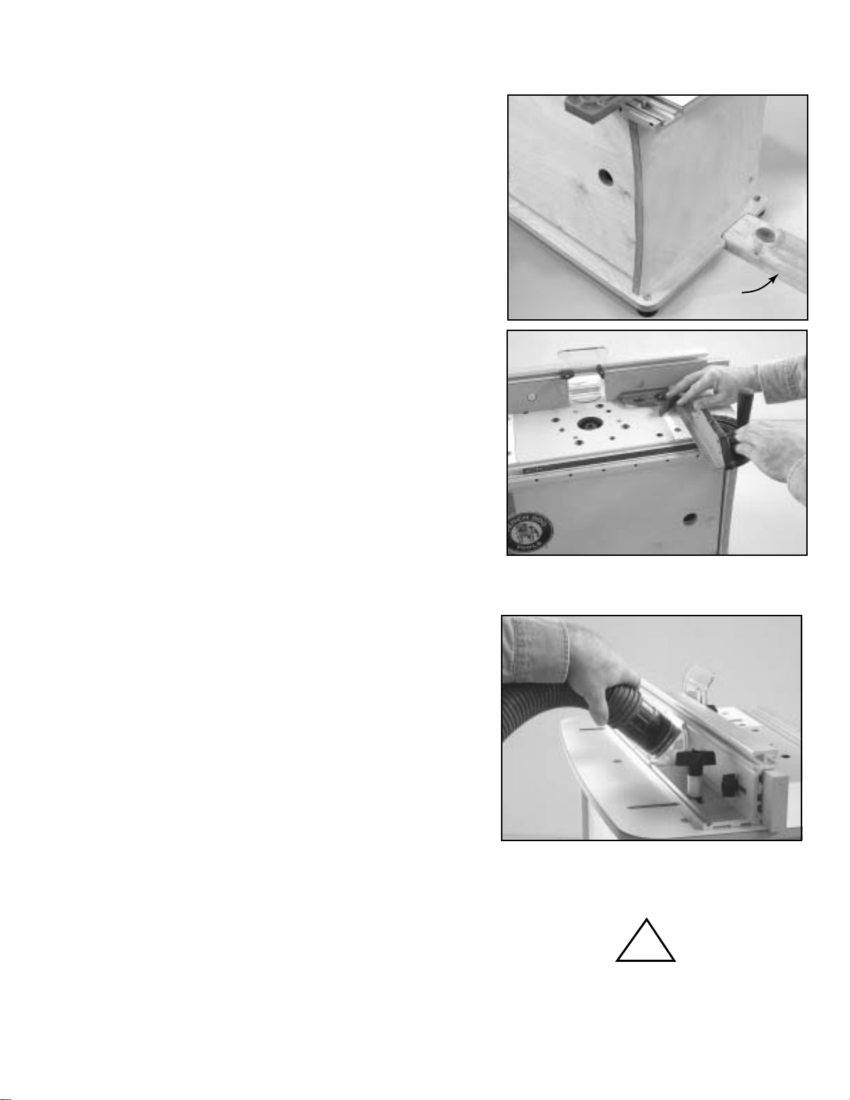
Securing the router table
The base has rubber feet to reduce vibration and slippage of
the base on a smooth surface. For permanent mounting, the
base can be bolted through the rubber feet to a workstation or
bench. For a secure yet portable mounting, the base is
equipped with two special recesses that accept scrap2x4
dimensional lumber. Fasten the scrap2x4pieces to your
bench using clamps or screws.
Using Your Miter Gauge
*Miter gauge not included.
The miter track has two slots: an accessory T-slot and a T-bar
compatible miter gauge slot. The accessory T-slot is the
narrower of the two. It accepts 1/4" hex bolts for attaching
Feather-Loc featherboards (see Bench Dog accessories) and
other fence accessories like Panel-Loc and Power-Loc. The
miter gauge slot is used in conjunction with a miter gauge, and
fits standard 3/8" x 3/4" miter bars (with or without the T-bar).
The miter gauge is not included.
To adjust fence perpendicular to miter gauge, set miter gauge
to 90º, and place in slot (make sure miter track is adjusted,
see step 12). Loosen the fence's lock knobs and align the
miter gauge to fence using a square, as shown.
2x4
Dust Collection
*Hose not included.
Temperature Regulation
To prevent router overheating periodically open the cabinet
door during use, and never let dust and debris collect inside the
cabinet. Always use a vacuum at the fence mounted dust port.
For extended operation you must install a dust port in the
cabinet or remove the door during operation. Immediately clean the dust and debris
from the inside of your cabinet after
each and every use.
!
Operational Tips
The integral dust collection port is designed to accept a
standard 2-1/2" fitting, typical on most shop vacs. Most of
these fittings actually measure 2-1/4" (outside diameter).
Bench Dog recommends 2-1/2" hose, or larger, because it is
more effective at evacuating dust and chips, and provides
proper air flow over the router motor. Any hose larger or
smaller than 2-1/2" requires an adapter you must provide. If
additional dust collection is needed, a dust port can be
added to your cabinet or motor area. DO NOT USE YOUR
ROUTER TABLE WITHOUT DUST COLLECTION!
Page 12
Fence
b
i
t
r
o
t
a
t
i
o
n
Fence
Fence
A classic trap resulting in a climb
cut. Always avoid this set-up!
This feed direction will
result in a climb cut because
the stock is trapped between
the fence and the router bit.
NO!
Proper feed direction
b
i
t
r
o
t
a
t
i
o
n
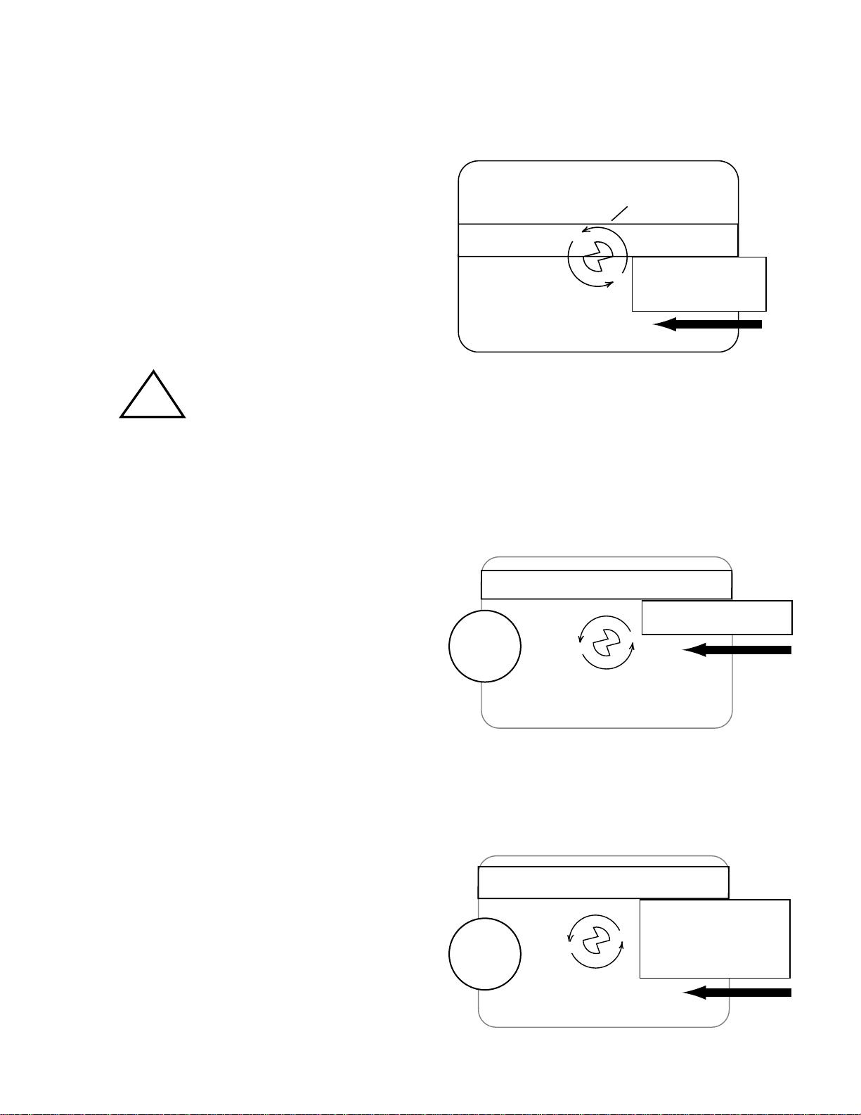
Avoiding Fence Traps
Fence traps occur when the work piece is fully
"trapped" between the router bit and fence. Fence
traps pose two real concerns: the possibility of climb
feeding, and human exposure to the router bit. As
stated earlier, climb cutting should be avoided as loss
of control of the operation is a possibility!
The top drawing shows a classic trap to be avoided.
What appears as a normal feed direction (working
from right to left) is wrong, and will instead produce a
climb cut. Because the work piece is trapped it can
easily be pulled from one's grip and thrown with great
velocity. Feeding the stock from left to right will
eliminate the climb cut but not the danger. It will be
difficult to keep the stock tight against the fence as the
bit's rotation will thrust the stock away from the fence.
Also, your body will be dangerously exposed to the
spinning router bit. The bit guard will not protect you
against flying stock, nor guard against this level of
exposure.
The second drawing is not a trap, as long as the router
bit cuts only partially into the stock. In other words, the
router bit must not completely cut through the
workpiece. In this cut, the bit will grab and push the
stock toward the fence. This is good, as the fence will
control the workpiece better than your hands. Typical
dado cuts resemble this set-up, and are commonly
performed on router tables. If the dado is to be
widened with two (or more) passes, be careful not to
set a classic trap or climb cut.
OK for
dadoes
only
Not a trap as long as the router bit does not
cut all the way through the stock.
Here the feed direction is
correct because the router
bit does not cut all the way
through the stock.
Never Climb Cut!
!
Feed Direction
routertop (top view)
workpiece
workpiece
workpiece
router bit rotation
Always feed the workpiece against the cutter
rotation, as shown. Feeding the workpiece with
the cutter rotation is called "climb cutting". Climb
cutting is very dangerous, because the cutter will
grab the workpiece and thrust it the same direction
as the cutter rotation. Even small router bits will
overpower your ability to hold onto the workpiece
during a climb cut.
Do not use this router table until you understand
proper feed direction and bit rotation. If climb
cutting is still unclear, ask your retailer for help,
give us a call, or reference a book on router table
usage.
A typical set-up. Here, the fence is
partially covering the router bit.

Page 13
Adjusting the Subfences
The (2) MDF (medium density fiberboard) subfences are
designed to slide along the fence approximately 2".
This results in a router bit opening from 0 to 4".
A. "Close" Setting
Many applications require adjusting the subfences close
to the router bit. This accomplishes nearly the same
benefits of a true "zero clearance" setting (see "B")
without cutting the subfences. Before the router is
turned on, and after the fence and router bit height are
properly adjusted, slide the subfences toward the bit to
reduce the gap. Confirm that the router bit can freely
rotate without touching the subfences!
B. "Zero Clearance" Setting
Cutting the subfences into the router bit profile produces
"zero clearance". Zero clearance eliminates the gap
between the fence and router bit. This prevents the
workpiece from getting pulled into the fence just before
the router bit. Moreover, a zero clearance setting
achieves a cleaner cut because the subfence supports
the workpiece fibers. If a true zero clearance setting is
desired, follow these steps:
1. Adjust the bit height and fence position. Note: the
subfences must NOT contact the router bit at this time.
2. Install the bit guard and secure.
4. Start router, and use dust collection. From the back of
the fence, slightly loosen the subfence knobs and
carefully slide the infeed subfence into the spinning
router bit. Hold onto the subfence knobs.
5. After the subfence has reached the guide bearing of
the router bit, fully tighten the knobs on the subfence.
Note: If the bit does not have a guide bearing (i.e.
vertical raised panel bits), slide the subfence half-way
into the bit, then tighten the subfence knobs.
outfeed subfence infeed subfence
outfeed subfence infeed subfence
Router Bit Guide Bearing
The infeed subfence is wide open, and the
outfeed subfence is set to "close".
Here the infeed subfence has been
adjusted to zero clearance.
!
Important Notes:
The outfeed subfence is rarely set to zero clearance,
because doing so has little performance benefit and can
damage the subfence. A "close" setting is more desirable for
most applications. Setting the outfeed subfence to zero
requires great care because the router bit can cause a
portion of the subfence to chip or break. If an outfeed zero
clearance is absolutely necessary, slide the outfeed
subfence very slowly into the bit to minimize the chipping
and tearing.
The subfences can be flipped when changing profiles or bit
heights. New, replacement subfences are available when a
new profile is to be created or if the subfence cannot be
trimmed to provide a fresh edge.
MDF works very well as a subfence because it is softer than
most woods and is much less likely to damage expensive
router bits. MDF also retains the shape of delicate profiles
and thus allows proper support for zero clearance settings.
When adjusting the fence, ensure that no part of the
aluminum fence body could contact the router bit.
Caution: Never adjust or slide the
subfences from the front! Always work
from the back with both hands on the
adjustment knobs.
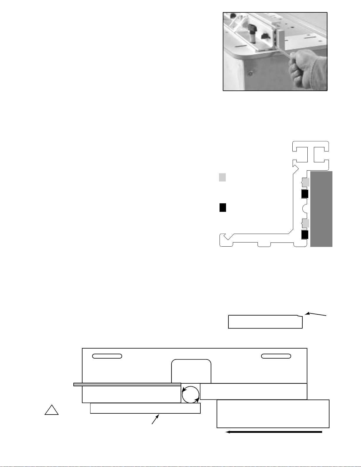
Jointing
Set-up the Fence
Jointing is the process of making flat, square and straight mating edges.
Jointing is necessary when two boards are edge glued to create a larger
panel. It is also used to "fit" pieces together, as well as to trim stock to
size.
Note: Jointing on a router table is not intended to replace a free-standing
power jointer, especially for stock wider than 1.25". However, jointing with
the router table does have advantages over the jointer. First, small and
short pieces of wood can be safely jointed because the opening of the
fence can be made very small: about 1/2". Second, the quality of the cut
is usually better because the router bit spins much faster than the
jointer's cutter head. A faster cutter speed is especially useful on woods
prone to tear-out, like bird's eye maple and quilted cherry. Be sure not to
move too slowly, as this will leave burn marks in your workpiece.
Your fence has built-in jointing slots to accept the (2) small aluminum
jointer bars that shipped with your router table. Installed in pairs, these
bars "shim out" the out feed subfence either 1/32" or 5/64" (2mm).
Unplug router and install a 1/2" diameter straight or spiral up-cut router
bit.
Caution: Use only 1/2" shank bits for jointing. The bit's cutting
length must not exceed 1.25". Set the bit height to 1.25" or less.
Loosen the outfeed subfence mounting knobs and slide both aluminum
jointer bars (always installed in pairs!) under the outfeed subfence in
either the 2nd and 4th slots, or the 1st and 3rd slots (see illustration).
Use a straight edge to adjust the router bit and outfeed subfence to the
same plane (see illustration below). Readjust if necessary. Remove
straight edge when done.
Slide both subfences toward the bit to decrease the amount of gap
around the router bit. Be sure the subfences are not touching the router
bit. Also be sure the router bit is not touching the fence's aluminum body.
Tighten the subfence knobs and place the bit guard in position.
First make a test cut in scrap stock. Readjust if necessary.
outfeed
subfence
Use slots 2 and 4 for
1/32" cuts.
Use slots 1 and 3 for
5/64" (2mm) cuts.
If board "snipe" occurs, realign the out-
feed subfence to the router bit. Don't be
surprised if it takes a few tries to master
this operation.
snipe
jointer bars
Always use a push
stick or push pad.
outfeed subfence infeed subfence
Feed Direction
workpiece
fence (top view)
straight edge - remove before jointing!!!
router
bit
Use a straight edge to set
outfeed subfence and
router bit to same plane.
(Bit guard not shown for clarity, only!)
!
In this photo, the user is sliding the
second bar into position. Be sure to
tighten the subfence knobs when done!
Note the small "v"
grooves. Always install
the bars in pairs.
Page 14
1
2
3
4
This manual suits for next models
2
Other Bench Dog Tools Tools manuals


Popular Tools manuals by other brands

Tohnichi
Tohnichi BQSP operating instructions

Axcaliber
Axcaliber Extra Dovetail Jig user manual

Weidmüller
Weidmüller STRIPAX operating instructions

Astro Pneumatic Tool
Astro Pneumatic Tool 45080 manual

Hilti
Hilti NPU 100-22 Original operating instructions

HOLZMANN MASCHINEN
HOLZMANN MASCHINEN HOB305PRO-SMW2 manual

Dynabrade
Dynabrade AutobradeRed DynaZip 18255 Operation instructions

Focused Technology Solutions
Focused Technology Solutions SpikeEase FTS20182 Operation manual

Jackco
Jackco 66300B user manual

Hitachi
Hitachi H90SE Handling instructions

kincrome
kincrome K15061 manual

Uponor
Uponor 1015764 operating instructions


