Benchmark Scientific Accuris Instruments MyGel InstaView User manual

Operating Manual
Version 1.0
MyGel™ InstaView
Electrophoresis System

Thank you for purchasing theAccuris MyGel™ Mini Electrophoresis System.
This operating manual includes a product introduction, operating and safety
information. Before using the MyGel InstaView, please read this manual in its
entirety and be sure to fully understand the features and methods for proper
operation. Keep this manual for future reference.
Please check the list of included components in section 1.1, and if there are
any parts missing, damaged, or incorrect, please contact your distributor or
Benchmark Scientific’s Customer Service Department at 908-769-5555 or by
email at info@benchmarkscientific.com.
Contents
1. Introduction………………………………………....................2
1.1 Included Component List…….………….…………….……..3
1.2 Diagrams of Included Components...................................4
1.3 Specifications.………………………….….............................6
2. Installation….…………………………………..……………….7
3. Warnings……………..………………………..........................7
4. Gel Preparation.……………………………….………….……8
5. Gel Tank Set Up ………………………………………………10
6. Power Supply Operation / Electrophoresis ..…...…...….12
7. Viewing Electrophoresis Progress…….……….…………13
8. Imaging using a smart phone…..…….……….…..……….13
9. Maintenance……………………………………….…………..14
10. Troubleshooting………………….…..…..............................14
2
1. Introduction
The MyGel InstaView is a complete horizontal electrophoresis system that
includes a power supply, gel running tank, safety lid with viewing filter, blue LED
transilluminator, and a gel casting set. The system is designed for separating
nucleic acids in agarose gels, and allows viewing the stained DNA bands during
electrophoresis without removing the gel from the tank. All components and
accessories are included for casting and running agarose gels.
The blue LED transilluminator and viewing filter are compatible with green
fluorescent stains such as Accuris SmartGlow PS, SmartGlow LD, SYBR® Green,
and other similar stains that fluoresce under 465nm blue light.
Before use, please read this operating manual in its entirety.
1.1 Included Components
Power Supply 1pc
Gel Running Tank Assembly 1pc
Blue Light LED Illuminator 1 pc
12VDC Power Supply (for LED Illuminator) 1 pc
Power cord for 115V/230V outlet 1 pc
Gel Casting Stand 1 pc
Gel Casting Divider 1 pc
Long Gel Tray (10.5 x 10cm) 1 pcs
Short Gel Tray (10.5 x 6cm) 2 pcs
Double Sided Comb (12/22 teeth) 2 pcs
AC transformer (only included with 230V model) 1 pc
User Manual 1 pc
3

2
1.2 Diagrams of Included Components
Safety Lid with Integral Viewing Filter
Gel Running Tank Power Supply AC Power Cord
Blue LED Transilluinator 12V Power Adapter
4
Smart phone imaging
enclosure with photo filter

Diagram of Included Components (Gel Casting Set)
Double Sided Comb (12/22 teeth)
Long Gel Tray (10.5 x 10cm)
Short Gel Trays (10.5 x 6cm)
Gel Casting Divider
Gel Casting Stand
5

1.3 Product Specifications
Power Supply
Input voltage 115V 50/60Hz or 230V 50/60Hz (Transformer
included with 230V input model)
Output voltage 35V, 50V, 100V
Max power 40 Watt
Timer 0 ~99min
Fuse 250V, 2A
Migration Tank
Dimension 120mm×110mm×45mm(inner dimension)
Buffer volume 200ml-225ml
Electrodes Platinum wire
Blue LED Transilluminator
Viewing area
dimension 10.5cm x 10.5cm
Wavelength 465nm
Input voltage 12VDC (Power Adapter included for 100VAC to
240VAC input)
Gel Casting Set
Gel casting stand Accommodates 10.5cm x 11cm and
10.5cm×6cm trays (Divider included)
Comb
specifications
Teeth width x Teeth thickness x Teeth no.)
3mm×1mm×22
5.6mm×1mm×12
Gel trays 10.5cm x 11cm and 10.5cm×6cm
6

3. Warnings
To avoid electrical shock, do not use this product with wet hands.
Please carefully read this instruction manual before operation to avoid
any personal injury. Only trained laboratory personnel should operate
the system.
Do not attempt to open or repair the MyGel system. Contact your
distributor or Benchmark Scientific for service.
Always use the MyGel in an environment with low humidity and low dust,
also keep away from water, direct sunlight / strong light, corrosive gas,
high magnetic fields, heaters, fires and other heat sources.
The power switch for the power supply is located on the top
of the control panel, press “I” to power on, “O” to turn off.
Do not detach the power supply module from the migration tank when
the power is on. Attempting to do so can cause damage.
Always turn off the power after operation. When not in use, detach
the power supply and store in an area that is free from moisture
and dust.
7
When operating, do not move or bump the system, do not put your
finger or any other objects into the migration tank.
2. Installation
Place the electrophoresis system on a smooth, level surface.
Connect one end of the power cord to the instrument and the other end to an
appropriate outlet, the input voltage should be between 100~120VAC. When the
input voltage is 220VAC, use the transformer inline.

4. Gel Preparation
Place the gel casting stand on a level surface,
and place the divider and desired gel trays
into the proper positions in the stand.
Either one long gel tray, or two short trays can
be inserted into the casting stand (see
diagrams on right)
Note: If the gel tray is not level, the thickness
of the gel will not be uniform and DNA
migration may be uneven.
Insert the comb(s) into the gel casting
stand as per photo on the right. Multiple
combs can be inserted depending on the
number of samples and desired run
distance.
8
Note: when using the fine toothed
comb, the flat side of the well comb
should be facing the direction of
DNA travel. See figure below.

Pour the agaose gel/DNA stain
solution into the gel tray to make a
gel approximately 4mm thick.
Each 6x10.5cm tray requires
about 25ml of agarose.
After the gel has solidified
(approximately 20 minutes) hold the
two sides of comb and gently lift it out
of the gel. The wells should be
straight and undamaged.
Carefully remove the gel tray with the
gel from the stand and place it into
the migration tank in the correct
orientation. (DNA samples will
migrate from the –to + electrode).
Note: After mixing and heating
agarose solution, let it cool to
approximately 60°C before
pouring into the gel trays
9
7
Note: Make sure that the MyGel System is
installed on a stable and level surface.
This will ensure even sample migration.
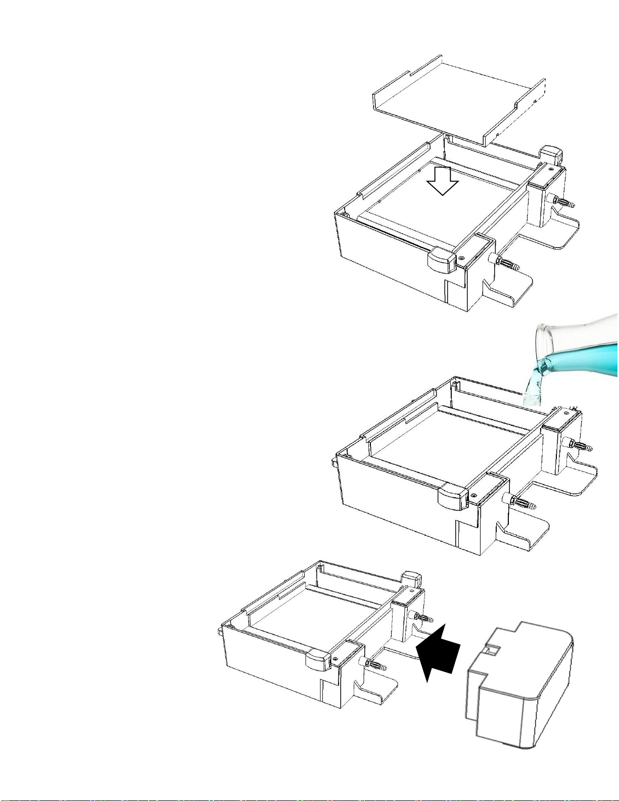
Place a prepared gel, together with the gel
tray onto the gel bed inside the gel tank.
10
Connect the power supply to the
migration tank.
Carefully pour an appropriate buffer solution to
a level about 2 mm above the surface of the
gel. Typically, 200ml of buffer is required.
It is recommended to use Accuris QuickSilver
TAE or TBE at a concentration of 0.5X, or
QuickSilver Fast Running buffer at a
concentration of 1X.
5. Gel Tank Set Up

8
Add DNA samples to the gel
Use an appropriate pipette to
carefully dispense samples into the
wells of the gel.
Note: Loading buffer should be
mixed with the DNA samples so they
will sink to the bottom of the wells.
Carefully lower the safety cover onto
the gel tank, making sure to align the
magnet with the sensor recess. The
orange viewing filter should fully
contact the surface of the buffer so
there are no bubbles visible. If the
buffer level is too low, remove the
cover, and add more buffer to the
tank.
11
Slide the blue LED illuminator under
the gel tank..
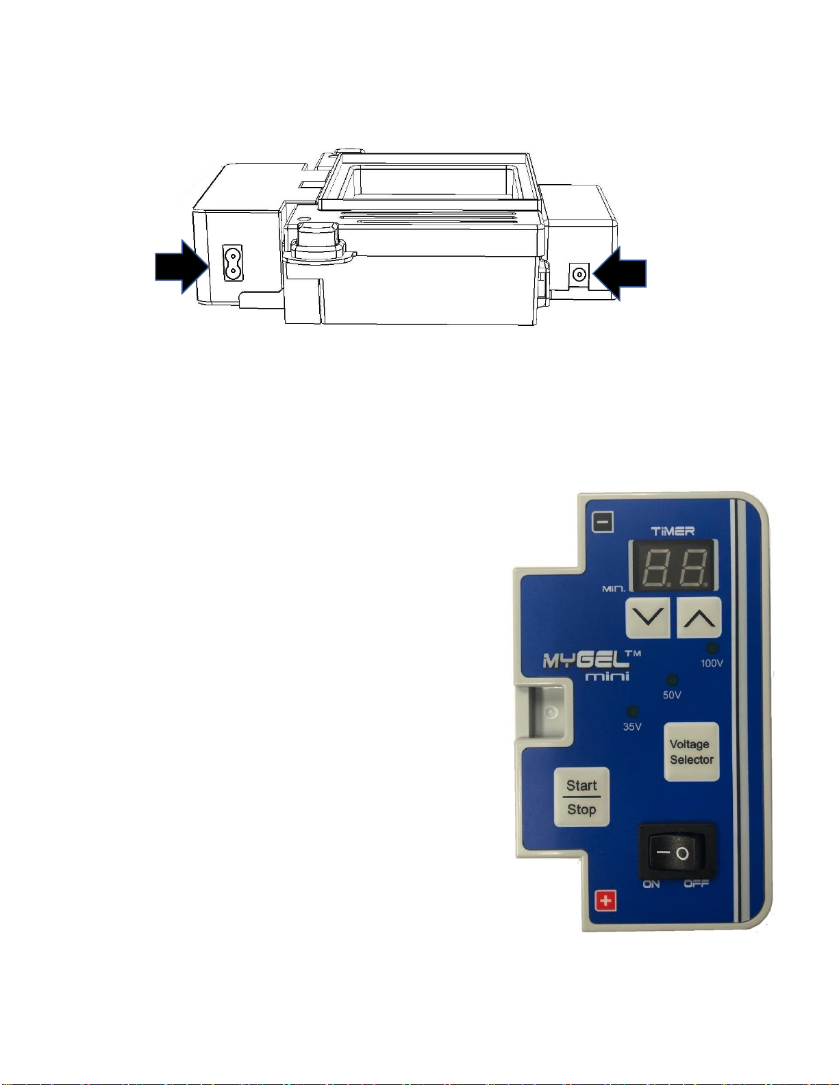
Press to set the run time from 1 to
99 min. For a continuous run, set the timer
to “00”.
Press the Voltage Selector button to toggle
through and select the appropriate output
voltage. The LED for the selected voltage
will light.
Press the “Start/Stop” button once to start a
run. The set output voltage LED will blink to
indicate a run is in process.At the end of a
timed run, the alarm will beep 3 times, and
the display will show “Ed” to indicate END.
Press any key to clear “Ed” and set up
another run.
To stop a run in process, press and hold
“Start/Stop” for 3 second. The voltage LED will
stop blinking to indicate the run has stopped.
If removing the gel the end of an
electrophoresis run, turn off the power
remove the lid and remove the gel tray.
Connect the
power cord to the
power supply and
plug into the
appropriate wall
outlet.
Connect the
12V power
supply to the
LED
transilluminator
12
6. Power Supply Operation / Electrophoresis

7. Viewing Electrophoresis Progress
8. Imaging using a smart phone
To visualize the DNA separation in
the gel during electrophoresis, turn
on the blue LED illuminator using
the ON/OFF switch.
It may be necessary to dim or turn
off ambient lights for best viewing
results.
The LED illuminator has a built in
timer, so the light will automatically
switch off after 5 minutes.
To take a picture of the gel using a
smart phone camera, fit the imaging
enclosure onto the lid of the gel
running tank.
Insert the included orange photo filter
into the top platform of the enclosure.
Turn on the smart phone’s camera
application, and align the camera lens
with the photo filter.
Zoom and focus as necessary to
optimize the image, and take the
picture.
13
9. Maintenance
Always disconnect the power cords for cleaning. When
cleaning the surfaces of the instrument and LED
transilluminator, use a damp cloth with mild detergent if
needed. Do not use any corrosive solutions that could
damage plastic.
When cleaning the gel tank, first separate the Power
Supply. Use water or neutral cleaner.
Use caution when cleaning the areas near the
platinum electrodes at the bottom edges of the gel
tank.
10. Troubleshooting
Problem Causes Resolutions
No display
Power not connected.
Switch failure. Fuse
blown.
Controller failure.
Check power supply, Unplug and re-
attach power cord. Check fuse.
Contact Benchmark for repair.
No Migration Power switch off, no
power, gel inserted
backwards
Turn on power switch. Check that gel
is properly oriented (DNA will migrate
towards + electrode)
Contact Benchmark for repair.
Abnormal
Electrophoresis
Distance Incorrect input voltage Check main power supply.
Abnormal heating of
buffer or gels
Buffer concentration
too high, voltage too
high
Use 0.5X TAE/TBE buffer, 1X
QuickSilver Fast Running Buffer, or
reduce running voltage.
Key function failure Control panel switch
failure Contact Benchmark for repair.
Clean gel casting stands, gel tray and combs with water or
a neutral cleaner.
14
Do not submerge the power supply or LED transilluminator
in water.

Problem Causes Resolutions
Error E1 Lid opened during run or
magnet switch problem. Seat lid properly. Check
magnet on lid..
Error E3 Lid not closed upon start or
magnetic switch problem.
Seat lid properly. Check
magnet on lid.
Error E5 Electric current not flowing
normally. Buffer missing, or
concentration too high.
Check proper buffer level in
the tank. Check buffer
concentration (1X or 0.5X
TAE or TBE is standard).
Check electrodes and
connections.
Error E7
Buffer concentration too high,
current too high, power over
50W, or internal electronic
problem
Check buffer concentration.
Replace electronic board.
Troubleshooting (continued)
Table of contents
Other Benchmark Scientific Medical Equipment manuals


Popular Medical Equipment manuals by other brands


OHIO WILLOW WOOD
OHIO WILLOW WOOD LimbLogic VS Series Prosthetist's Guide

Physipro
Physipro Zero Pressure owner's manual

Codonics
Codonics Horizon ChromaVista quick start guide

Iridex
Iridex PASCAL Synthesis TwinStar Operator's manual

Seers Medical
Seers Medical ST4552 operating instructions

Medisana
Medisana 51082 quick start guide


