OHIO WILLOW WOOD LimbLogic VS Series User manual

1
This document provides instruction for the prosthetist in
the installation and use of the system. A separate document,
LimbLogic VS Patient Information, is included with each
system and should be provided to the patient upon delivery
of a prosthesis containing the LimbLogic VS.
The Vacuum Pump and fob included in this package are
electronically keyed together and can be used only with
each other.
LimbLogic VS - 1600 Series is now waterproof.
Prosthetist’s
Guide

2
This pump is only designed to move air; use of Vaseline®
or similar lubricating creams inside the socket will clog the
pump. Do not allow foreign substances to be pulled through
the Vacuum Pump. This may impair function of your vacuum
system.
Do not allow acetone to contact the Vacuum Pump or fob.
The LimbLogic VS is not intended to be used as the only
means of attachment of prosthesis to patient.
All LLVS components have passed safety testing for use as
medical devices. Radio enabled devices transmit with a power
of less that one milliwatt and comply with United States and
international guidelines for low power transceivers. If LLVS
components will be used around safety critical devices such
as pacemakers or defibrillators, consult the manufacturer
for appropriate usage instructions. Consult the section on
Regulatory Information for more information on safety and
compliance.

3
Table of Contents
Page
Quick-Start Guide ..................................................................................4
Keys to Successful Use ..........................................................................5
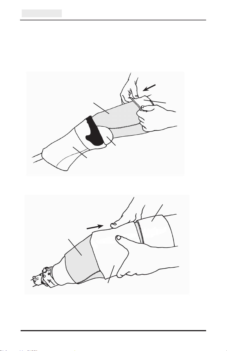
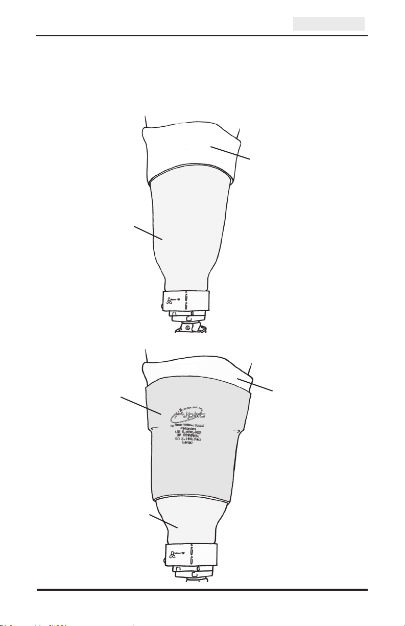
BK Application................................................................................6
AK Application................................................................................7
Introduction............................................................................................8
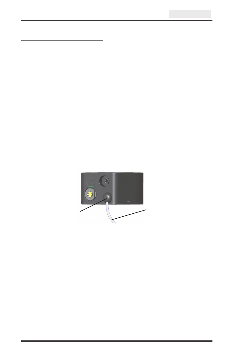
Vacuum System Function ......................................................................8
Charging the Vacuum Pump Battery......................................................9
Charging the Vacuum Pump Battery in a Vehicle..........................10
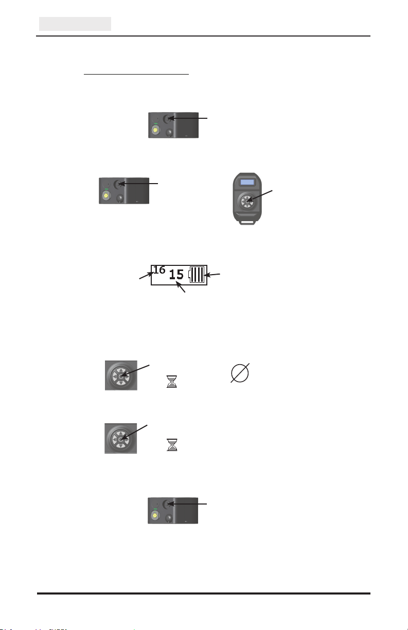
Turning on the Vacuum Pump..............................................................11
Turning on the Fob...............................................................................12
Information Screen...............................................................................13
Active Mode ..................................................................................13
For Bilateral Applications.......................................................14
Standby Mode................................................................................14
Configuration Screen ...........................................................................15
Detecting a Leak ..................................................................................16
If the Sealing Sleeve is Punctured........................................................16
No Radio Connection...........................................................................17
Low Battery Mode ...............................................................................17
Turning Off the Vacuum Pump ............................................................17
Cleaning the System ...........................................................................18
Exposure to Water ................................................................................18
Accessories ..........................................................................................19
Troubleshooting Guide ........................................................................20
Diagnostic Kit Instructions ..................................................................24
Warranty...............................................................................................25
Regulatory Information........................................................................27

4
Quick-Start Guide
or
Press and hold
center button
until LimbLogic VS
logo appears
in display
3. Information about the system is displayed.
current vacuum level
current upper
set point
(press up and down
buttons to adjust,
and center button
to conrm)
Vacuum Pump
battery charge level
4. To enter Standby Mode:
Press
center button
until appears
Standby
Mode
Press
center button
until appears
To resume vacuum regulation:
2. Start regulating the vacuum.
Overview
5. Turn off the Vacuum Pump.
1. Turn on the Vacuum Pump.
Press
one time
Press
two times
Press
one more
time

5
Keys to Successful Use
1. Fabricate a non-porous Total Surface Weight Bearing socket
using a LimbLogic VS 4-Hole Attachment Plate. This is critical to
the proper operation of the system. Be sure to follow the fabrication
instructions provided with the 4-Hole Attachment Plate.
Prior to delivering the prosthesis, you may want to use the Diagnostic
Kit (LLV-1300) to confirm that there are no leaks in the system.
2. Fully charge the Vacuum Pump. (Refer to “Charging the Vacuum
Pump Battery” on page 9.)
3. Properly secure the fully charged Vacuum Pump to the socket,
Vacuum Plate (LLV-01043), or Vacuum Pyramid (LLV-01044) with
M6 flathead screws. Tighten the screws to 9 ft-lbs (12 Nm).
4. Assemble the prosthesis, inserting one end of the exhaust port tubing
into the exhaust port. Attach the other end of the tubing as desired.
5. Have the patient don an Alpha®Liner, the prosthesis, and an Alpha
Sleeve.
For the best seal proximally, t
he patient should fold over the
top edge of the liner and roll the sleeve up onto the folded edge
to create a gel-to-gel seal, as shown in the figures on pages 6 and 7.
Overview
Exhaust Port Exhaust Port
Tubing

6
Gel side of
Alpha Liner
Gel side of
Flex Sleeve
Fabric side of
Flex Sleeve
Overview
Figure 1:
Folding over the top
edge of the liner
Socket
Alpha Flex
Sleeve
Fabric side of
Alpha Liner
Gel side of
Alpha Liner
BK Application
The patient should don an Alpha Liner and Alpha Flex Sleeve as shown
below.
Figure 2:
Rolling the sleeve
up onto the folded
edge of the liner

7
Overview
AK Application
The patient should don an Alpha Liner and Alpha AK Sleeve as shown
below.
Figure 3:
Top edge of the liner
is folded over the
brim of the socket
Socket
Gel side of
Alpha Liner
Gel side of
Alpha Liner
Fabric side of
AK Sleeve
Figure 4:
Sleeve is rolled up
onto the folded edge
of the liner
Socket

8
Introduction
The LimbLogic VS is a remote-controlled
vacuum suspension system. The Vacuum
Pump is mounted inline on a prosthesis
to allow for complete integration without
the annoyances of tubes into the socket.
LimbLogic VS operates quietly and
features “Set and Forget” monitoring,
which means that the system monitors
the level of vacuum in the socket to
maintain a secure and comfortable fit.
Vacuum System Function
The system monitors the vacuum level and draws more vacuum as
needed to maintain the level between a minimum value (the Lower Set
Point) and a maximum value (the Upper Set Point). The difference
between the Lower Set Point and the Upper Set Point is called the
Vacuum Control Range. The Upper Set Point cannot be set higher
than the User Maximum. The User Maximum cannot be set higher than
the System Maximum of 20 in-Hg.
The prosthetist may adjust the User Maximum as well as the width of the
Vacuum Control Range. Both the prosthetist and the patient may adjust
the Upper Set Point.
The optimum vacuum setting is different for each amputee. Keep
in mind that a higher vacuum level is not always better. Higher
vacuum levels require that the Vacuum Pump use more power and
will therefore discharge the battery faster.
Vacuum Control Range
0 in-Hg
User
Maximum
Lower
Set Point
Upper
Set Point
20 in-Hg
(System Maximum)
Overview

9
Charging the Vacuum Pump Battery
1. Remove the cap from the charging port on the Vacuum Pump.
2. Insert the charging plug into the charging port as follows:
a) Gently insert the plug into the port, holding the black plastic
portion of the plug, with just enough force to feel the plug touch
the port.
b) Align the green alignment marks on the charging port and the
charging plug.
The charging plug can only be inserted into the Vacuum
Pump charging port in one orientation. Forcing the plug will
damage the plug, will possibly damage the vacuum system,
and will void the warranty.
3. Plug the charger into a power outlet. The blue light on the two-pronged
adapter will light, followed by the green LED. The fob will display the
battery charging indicator.
If the green LED does not light, press and hold the reset button until
the light comes on.
4. When charging is complete, the green LED will flash. Disconnect
the power cord from the Vacuum Pump and from the power outlet.
charging port
Charger
Vacuum Pump
To
AC
outlet
Green LED
SOLID = charging
FLASHING = charged
charging plug
reset button
Align the green
mark on the plug
with the green
mark on the port.
Overview
charger node

10
5. Reinstall the cap onto the charging port on the Vacuum Pump.
Use ONLY an Ohio Willow Wood charger. For LLV-01042
series Vacuum Pumps use Ohio Willow Wood charger part
number LLV-01011. For LLV-01040 series Vacuum Pumps
use Ohio Willow Wood charger part number LLV-01010.
Use of any other charger may result in damage to the
Vacuum Pump or the charger or both.
If the charger needs to be reset, press the reset button. With normal
usage, the rechargeable battery should last for the life of the product.
Charging the Vacuum Pump Battery in a Vehicle
To use a vehicle’s power to charge the Vacuum Pump, you must purchase
a Power Inverter rated at 75 Watts or less to convert the vehicle’s 12V DC
power to 120V AC. Examples of acceptable Power Inverters include the
Digital Concepts 75 Watt Portable Power Inverter (available from general
retailers) and the Radio Shack® 75 Watt Power Inverter (Catalog
Number 22-153).
1. Plug the Power Inverter into the vehicle’s cigarette lighter socket.
2. Connect the charger to the Vacuum Pump.
3. Plug the charger’s two-pronged adapter into the Power Inverter’s
three-pronged receptacle.
Overview

11
Turning on the Vacuum Pump
Press the on/off button on the Vacuum Pump one time. The pump will
vibrate four times.
Note: if the pump has just been unplugged from the charger, the button
does not need to be pressed.
When you are ready for the pump to begin regulating the vacuum,
press the on/off button again (or turn on the fob, as described on the
next page). The pump will operate until the preselected vacuum level is
reached.
Overview
on/off button

12
Turning on the Fob
Up/down buttons:
adjust vacuum setting
Center button:
apply setting
Right/left buttons:
toggle between right
and left Vacuum Pumps
(bilateral only)
center
button
right
button
up
button
left
button
Overview
down
button
Press and hold the center button on the fob until the LimbLogic VS
logo appears and the display has reached the desired brightness.
Release the button. If the Vacuum Pump is charged and powered, the
Information Screen will be displayed.
The fob shuts off after one minute of non-use. This will not affect the
Vacuum Pump. Press and hold the center button to restart the fob.

13
Information Screen
The Information Screen indicates important details about the operation of
the system.
The vertical bars inside the battery symbol on the right side
of the screen indicate the amount of charge left in the Vacuum
Pump battery.
As the battery is discharged, the bars disappear from left to right.
A) Active Mode
When numbers are displayed to the left of the battery symbol, as
shown below, the system is in Active Mode. In this mode, the Vacuum
Pump activates as needed to maintain the vacuum settings.
You or the patient may use the up/down buttons to adjust the Upper
Set Point as desired. This is the only setting the patient may adjust.
The Upper Set Point cannot be set higher than the User Maximum.
Press the center button to save the change. The hourglass
symbol will appear to indicate that the setting is being saved.
current upper
set point current vacuum level
Overview

14
For bilateral applications:
The Information Screen displays right and left indicators to show
which pump is currently communicating with the fob.
Use the right/left buttons to select the right or left Vacuum Pump, then
press the center button to save your selection.
The LimbLogic VS logo will appear, followed by the Information
Screen for the selected pump.
In this example, the fob is
communicating with the
LEFT pump
In this example, the fob is
communicating with the
RIGHT pump
B) Standby Mode
Allows you to turn off the pump temporarily to prevent the pump from
regulating the vacuum.
To enter Standby Mode, press and hold the center button until
the hourglass symbol appears.
The standby indicator will then appear to indicate that the
pump is not regulating.
To return to Active Mode, press and hold the center button until
the hourglass symbol appears.
After six hours of Standby Mode without radio communication, the
unit will turn off. To turn the pump back on, either press the on/off
button on the Vacuum Pump one time or plug in the charger.
Keep in mind that a Vacuum Pump in Standby Mode will
continue to use the pump battery.
Overview

15
Configuration Screen
The system is shipped with the User Maximum set at 20 in-Hg and
the Vacuum Control Range set at 6 in-Hg. If these settings are not
sufficient for your patient, you may adjust them as follows:
With the Information Screen displayed, press the left and right
buttons simultaneously.
After the warning screen flashes,
you will see the Configuration Screen.
Use the right and left buttons to adjust the User Maximum.
The User Maximum cannot be set higher than 20 in-hg.
Press the up or down button to scroll to the next screen.
Use the right and left buttons to adjust the Vacuum Control
Range. The Vacuum Control Range cannot be set lower
than 4 in-hg.
Note: Increasing the Vacuum Control Range and decreasing the User
Maximum setting may reduce pump cycling and may increase pump
battery life.
Press the center button to exit the Configuration Screen and
save all current settings.
In this example,
the Vacuum Control Range
is set at 4 in-Hg
In this example,
the User Maximum
is set at 18 in-Hg
Overview

16
Detecting a Leak
If the leak indicator appears when the patient initially dons the
prosthesis, the patient should restart the pump.
If the leak indicator appears frequently while the patient is
walking, use the Diagnostic Kit (LLV-1300) to determine the
source of the leak.
To resume automatic vacuum regulation after a leak has been detected:
•Press the center button on the fob until the hourglass symbol appears,
or
•Press the on/off button on the Vacuum Pump one time.
If the Sealing Sleeve is Punctured
The latex sleeves (LLS-3N, LLS-4N, or LLS-5N) in the
Diagnostic Kit are to be used ONLY as a diagnostic tool for
locating the source of a leak. If a leak is fixed by replacing a
sealing sleeve with a latex sleeve, then the patient should receive
a new sealing sleeve immediately. The patient should NOT be
sent home with a latex sleeve, because the mineral oil in the
Alpha gel causes the latex to lose its elasticity.
Overview

17
No Radio Connection
If the No Radio Connection indicator appears:
•make sure the Vacuum Pump has been turned on
•make sure the Vacuum Pump battery has been charged
•make sure the fob is within 3 feet of the Vacuum Pump
• make sure the fob is more than 3 inches away from the
Vacuum Pump
If the No Radio Connection indicator still appears, contact
Ohio Willow Wood.
Low-Battery Mode
If the Vacuum Pump battery has less than 15% of its capacity
remaining, the Vacuum Pump enters a “stutter” mode.
(Stutter mode is when the pump quickly turns on and off when pulling
vacuum.) Charge as soon as possible.
The fob will display the battery charging indicator when the
unit is plugged into the charger.
Turning off the Vacuum Pump
Press the on/off button on the Vacuum Pump two times. The Vacuum
Pump will vibrate twice.
If the current vacuum level is near the current Upper Set Point, the
Vacuum Pump may skip the vibrations to prevent the vacuum level
from exceeding the Upper Set Point.
Overview

18
Cleaning the System
Once a month, the patient should pour 1/8 cup of distilled water or
rubbing alcohol into the socket, place the end of the exhaust port tubing
into a cup, and activate the Vacuum Pump. Use ONLY distilled water
or rubbing alcohol to clean the system.
Do not use acetone or similar chemicals to clean the system.
Please demonstrate this procedure for the patient before sending the
patient home with the system.
Exposure to Water
The Vacuum Pump is waterproof in fresh water up to a depth of 10 feet or
3 meters for up to 12 hours. The Vacuum Pump should not be submersed
in salt water. Be sure to dry off the Vacuum Pump if it is exposed to rain or
other moisture.
The fob is not water resistant. Submersion of the fob will void the warranty.
Overview

19
Accessories
Cosmesis Kit
The Cosmesis Kit (LLV-01046) extends the Vacuum Pump’s charging
port and on/off button so that they are flush with the surface of a
cosmetic cover. The kit also includes a hose barb for routing the exhaust
tube into the foot shell.
Vacuum Plate/Pyramid
The Vacuum Plate (LLV-01043) and Vacuum Pyramid (LLV-01044) can
be used for attaching the Vacuum Pump in line with other endoskeletal
components, instead of attaching the pump directly to the socket.
Overview
Vacuum Plate Vacuum Pyramid

20
Problem Action
The pump does not
vibrate when the on/
off button is pressed
once and the charger
is not connected to the
pump.
• Thepump’sinternalbatterymaynotbe
charged. Charge the pump with the charger
foratleast30minutesandtryagain.
• Theon/offbuttoncouldbedamaged.Verify
thattherubberbootisintactandhasn’tbeen
tornfromimpact.ContactOhioWillow
Woodiftheswitchneedstobereplaced.
• Thepumpmayhavebenexposedtoalarge
staticdischarge.Pluginthechargerand
press the reset button to reset the pump. The
chargerdoesnotneedtobepluggedintoan
outlet.
Pressing the pump
button, waiting for the
start-up vibrations,
and then pressing the
button again does not
start the pump.
(Topreventexcessive
vacuum, the pump
willnotvibrateifit
isalreadyholdinga
vacuum when it is
started up.)
• Donotpresstheon/offbuttontooquickly.
Pressthebuttonforonesecond,thenrelease
for one second before pressing again, so
thatthesystemrecognizesseparatebutton
presses.
• Thepump’sinternalbatterymaynotbe
charged. Charge the pump with the charger
foratleast30minutesandtryagain.
• Thepumpcouldalreadybeinautomatic
mode. Pressing twice when the unit is in
automaticmodeorstandbymodewillturn
theunitcompletelyoff.Wait15seconds,
thenpresstheon/offbuttononceandverify
that the pump vibrates to indicate it is in
standbymode.Aftervibration,pressa
second time to transition the pump to
automatic mode.
• Thepumpmayhavebenexposedtoalarge
staticdischarge.Pluginthechargerand
press the reset button to reset the pump. The
chargerdoesnotneedtobepluggedintoan
outlet.
Troubleshooting Guide
Overview
continued on next page
This manual suits for next models
1
Table of contents