Bend-Tech Dragon mAchines User manual
Part 1 of 1
Material Coolant System
Assembly Manual
Revision 7 | English ©2021 Bend-Tech LLC
Dragon Machines

ii Bend-Tech Dragon
Material Coolant System Assembly Manual
©2021 Bend-Tech LLC
All rights reserved. The information in this manual is subject to change without notice.
Bend-Tech LLC strives to produce the most complete and accurate information regarding
its products. We are constantly working to improve and advance our products to increase
performance, user satisfaction and experience. Bend-Tech LLC assumes no responsibility for
errors or omissions regarding this manual. Bend-Tech LLC assumes no liability for damages
resulting from the use of the information contained in this publication.

iiiBend-Tech Dragon
Material Coolant System Assembly Manual
Dragon Machines
Material Coolant System
Assembly Manual
Revision 7
English
Original Instructions
August 2021
Bend-Tech, LLC
729 Prospect Ave.
Osceola, WI 54020 USA
(651) 257-8715
www.bend-tech.com

iv Bend-Tech Dragon
Contents
Material Coolant System Assembly Manual
Contents
Contents..........................iv
Limited Warranty ...................v
Customer Satisfaction Commitment. . . . . vi
Customer Service. . . . . . . . . . . . . . . . . . . vi
01
Parts and Equipment .............. 7
1.1 Parts List ......................7
1.2 Tools and Equipment .............8
02
Material Coolant System
Assembly ................................. 9
2.1 Overview ......................9
2.1.1 Cooling System Assembly Tools 9
2.2 Coolant Tray Components ........ 10
2.2.1 Parts Catcher and Support Leg
Removal ...................... 10
2.2.2 Support Leg Gusset......... 10
2.2.3 Leveling Feet ...............11
2.2.4 Parts Catcher...............11
2.2.5 Attach Water Tray to Parts
Catcher ....................... 12
2.2.6 Water Tray System Assembly . 13
2.2.7 C-Bracket................. 14
2.2.8 Support Leg Braces......... 14
2.2.9 Finishing the Coolant Tray
Assembly ..................... 15
2.3 Water Tray Drain System ......... 15
2.3.1 Bung Installation ........... 15
2.3.2 PVC Drain Installation ....... 16
2.3.3 Tray System Drain Diagram. . . 16
2.3.4 Placing the Cooling System
Reservoir ..................... 16
2.4 Water Pump ................... 16
2.4.1 Water Pump Requirements ... 17
2.4.2 Recommended Water Pump
.................. 17
2.5 Hose System .................. 17
2.6 Connect the Pump .............. 17
2.7 Install the Water Pump........... 17
2.8 Attaching the Hose to the Rail Beam 18
2.9 Hose Reel Mount ............... 18
2.10 Hose Reel ................... 19
2.11 Trolley Hose Mount ............ 19
2.12 Connect the Hose ............. 20
2.13 Leveling the Coolant Trays. . . . . . . 20
2.14 Sealing the Coolant Trays ....... 20
2.15 Control Box Guard ............. 21
2.16 Fill the Reservoir .............. 21
2.17 Plug Adapter. . . . . . . . . . . . . . . . . . 21

vBend-Tech Dragon
Contents
Material Coolant System Assembly Manual
Limited Warranty
Covering Bend-Tech Dragon
Bend-Tech, LLC provides a limited warranty on all new Dragon machines that are
manufactured directly or under license by Bend-Tech, LLC, and sold by Bend-Tech, LLC or its
approved distributors.
Warranty Coverage
Each Bend-Tech Dragon machine is warrantied by the manufacturer against defects in material
workmanship for 12-months. The warranty period commences upon delivery of the Dragon
machine to the customer’s facility.
Repair or Replacement Only
The Manufacturer’s sole liability, and the Customer’s exclusive remedy under this warranty
shall be limited to repairing or replacing the defective part. Repair or replacement of parts
is at the sole discretion of the manufacturer. The Customer is responsible for warranty parts
installation. Bend-Tech does not provide warranty service labor.
Limits
This warranty does not cover components subject to wear due to normal use of the machine
such as belts, lights, tooling etc. This warranty is void if Bend-Tech, LLC has determined any
failure is the result of mishandling, abuse, misuse, improper installation, improper storage,
become void or limited in the event that hardware changes or adaptations are made to the
machine.
Software
Dragon software is covered by a 2-year maintenance plan from the purchase date of the
Dragon machine. After the 2-year maintenance plan is expired, the Customer can purchase
a maintenance plan. A maintenance plan will ensure the customer always has the newest
version of Dragon software. The maintenance plan is critical to keeping Dragon software
updated with the newest capabilities possible, and is critical to the servicing of the machine.
Bend-Tech, LLC will contact the Customer regarding updates to the maintenance plan within
1-month of expiration. Contact Bend-Tech Support to ensure software is up to date: support@
bend-tech.com.

vi Bend-Tech Dragon
Contents
Material Coolant System Assembly Manual
Customer Satisfaction Commitment
Congratulations on your purchase of the world’s best CNC plasma tube and pipe cutting
machine, the Bend-Tech Dragon. Bend-Tech LLC places great pride in customer satisfaction
our support is a key factor in your success.
Contact Us
Bend-Tech’s hours of operation are Monday - Friday, 8:00 - 5:00 EST. The Bend-Tech support
team and sales team are always available during our hours of operation.
Phone: 651-257-8715
Email: Sales team: [email protected]
Address: Bend-Tech, 729 Prospect Ave., Osceola, WI 54020, U.S.A..
Customer Service
Comments, questions, or concerns regarding the Dragon Machine, this manual, or the Bend-
Tech Software can be directed to Bend-Tech sales and service representatives at the above
contact information. Check out the following links for more information regarding Dragon
Machines and Bend-Tech Software.
Website, Socials, and Online Resources
• http://www.bend-tech.com
• https://www.facebook.com/2020ssi
• https://www.instagram.com/bend_tech
• https://www.youtube.com/bendtech2020
• http://www.bend-tech.com/wiki7

7Bend-Tech Dragon
Parts and Equipment
01
Material Coolant System Assembly Manual
01
Parts and Equipment
1.1 Parts List
Cooling System
• Plug Kit
• Aluminum Trays (3)
• Aluminum Support Legs (3)
• Parts Catcher/Control Box Cover Box
• Reservoir
• Hose Reel
• Hose Reel Mount
Cooling System Hardware
(shipped inside water reservoir)
• Hardware Bag
• Material Rollers (3)
• Clear Silicone (1)
• PVC Cement (1)
• Cushion Clamps (6)
• Leveling Feet (6)
• Disposable Mesh Bags (2)
• 8 in. zip ties (8)
Fastener Bag
• Nuts (54)
• Washers (54)
• ¾ in. Button Head Hex Screws (40)
• 1 in. Button Head Hex Screws (14)
PVC Components
• Coupling (5)
• Union (3)
• Bung (4)
• Tee (2)
• Elbow (2)
• Pipe (11)

8Bend-Tech Dragon
Parts and Equipment
01
Material Coolant System Assembly Manual
1.2 Tools and Equipment
Reel and Hose Hardware
• ¼-20 T-nuts (6)
• ¼-20 ½ in. Hex head screws
• Flanged hex head screws (8)
•
• Small Tube Plug Adapter
• Large Tube Plug Adapter
• ¾ in. Barb x ¾ in. FGHT w/ rubber grommet
• Hose Clamps (2)
Cooling System Tools List
•
• Rubber Mallet
•
•
•
•
•
• ½ in. wrench
• Flat head screwdriver

9Bend-Tech Dragon
Material Coolant System Assembly
02
Material Coolant System Assembly Manual
02
Material Coolant
System Assembly
2.1 Overview
The Dragon Material Coolant System enables the machine to achieve cleaner cuts with less
dross or slag. The material coolant system also reduces plasma dust and toxic gas during
the cutting process. While the material coolant system will help the Dragon machine achieve
steel.
2.1.1 Cooling System Assembly Tools
Before assembling the material coolant system, ensure the required tools are available. The
following tools are required to assemble the material coolant system:
Tools Needed
•
•
•
•
•
•
•
• Slotted or Flat blade
screwdriver
• Punch or small Phillips
screwdriver
• Utility knife
• Rubber mallet or plastic dead
blow hammer
• Large channel lock pliers
10 Bend-Tech Dragon
Material Coolant System Assembly
02
Material Coolant System Assembly Manual
2.2 Coolant Tray Components
The coolant trays are placed at the Head of the machine. The coolant trays serve as both parts
catcher and coolant drainback system for the coolant system. Before beginning assembly,
ensure that all components for the coolant trays are present. The coolant Trays consists of:
• Aluminum Trays (3)
• Aluminum Support Legs (3)
• Parts Catcher (1)
• Support Leg Braces (6)
• Parts Rollers (3)
• Leveling Feet (6)
• C Bracket (1)
2.2.1 Parts Catcher and Support Leg Removal
It will be necessary to remove the parts catcher, parts tray, and support leg from the Beak
remove the four screws that hold the parts catcher at the front and back end of the Beak.
Remove the eight screws that hold the parts tray where the Beak mounts to the Head of the
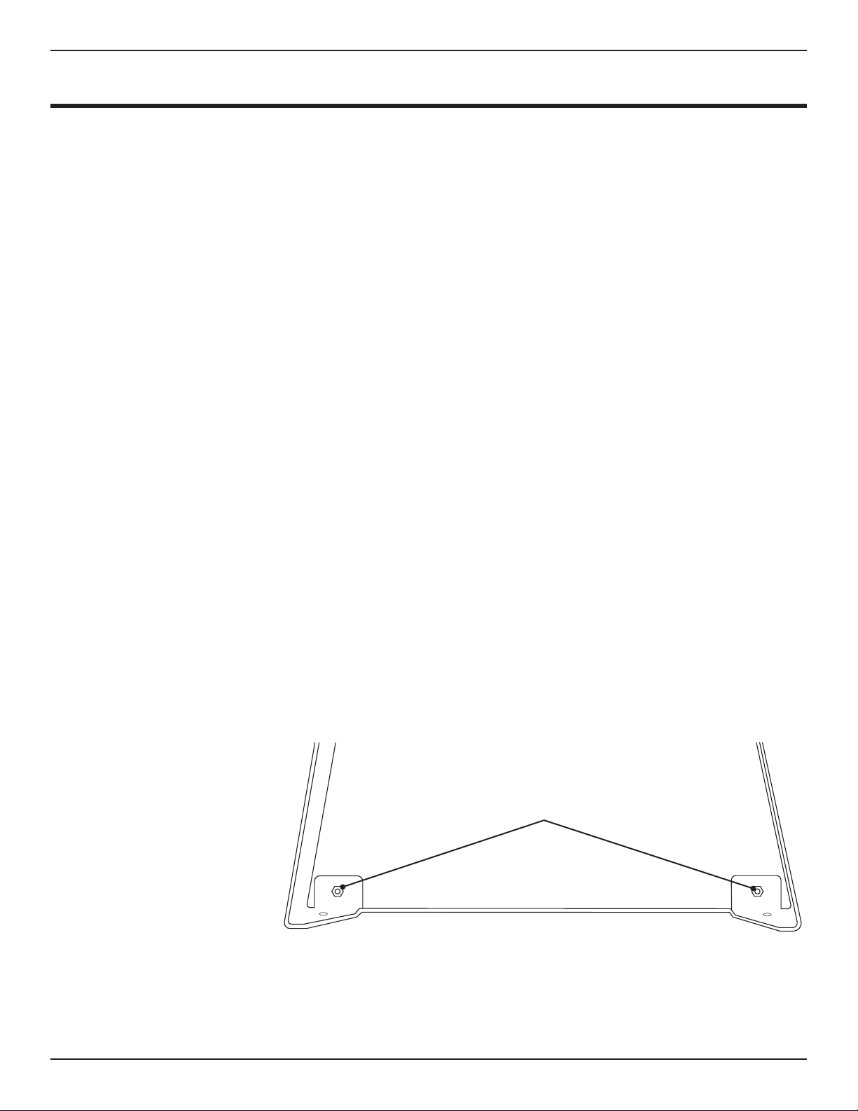
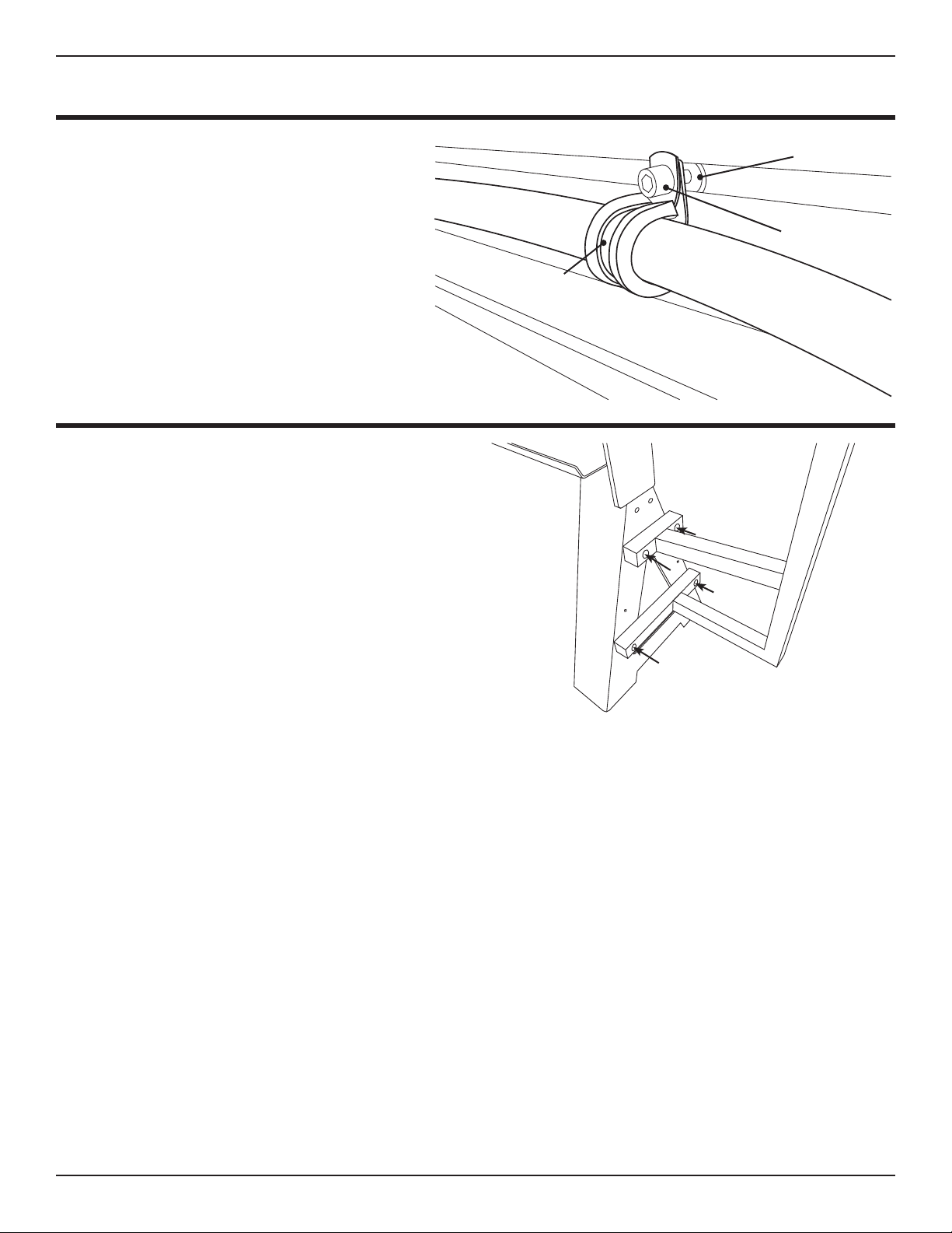
2.2.2 Support Leg Gusset
The bottom of each support leg is constructed with an integrated gusset design. In each
corner, secure the gusset using a 1 in. Button Head Hex Screw, washers and nut. Place a
washer on the 1 in. Button Head Cap Screw and insert into the hole in the Support Leg and
gusset. Place a washer on the inside and thread a nut onto the Button Head Cap Screw. Use
and ratchet to tighten
the nut, securing the
gusset. 1 in. Button Head
Cap Screw

11Bend-Tech Dragon
Material Coolant System Assembly
02
Material Coolant System Assembly Manual
2.2.3 Leveling Feet
Locate the Leveling Feet in the hardware bag. Thread a nut onto each leveling foot, leaving
about an inch between the base of the foot and the nut. Insert a Leveling Foot into the hole at
the bottom of each Aluminum Support Leg.
Thread a second nut
onto the Leveling
Foot after inserting it
in the mounting hole
on the bottom of the
Aluminum Support
Leg. Do not tighten.
Leave space for
adjustment of the
support legs.
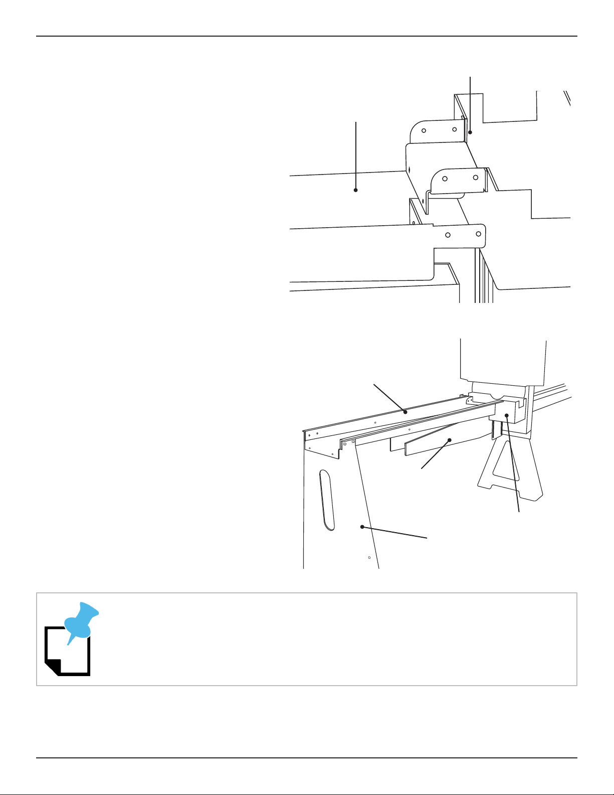
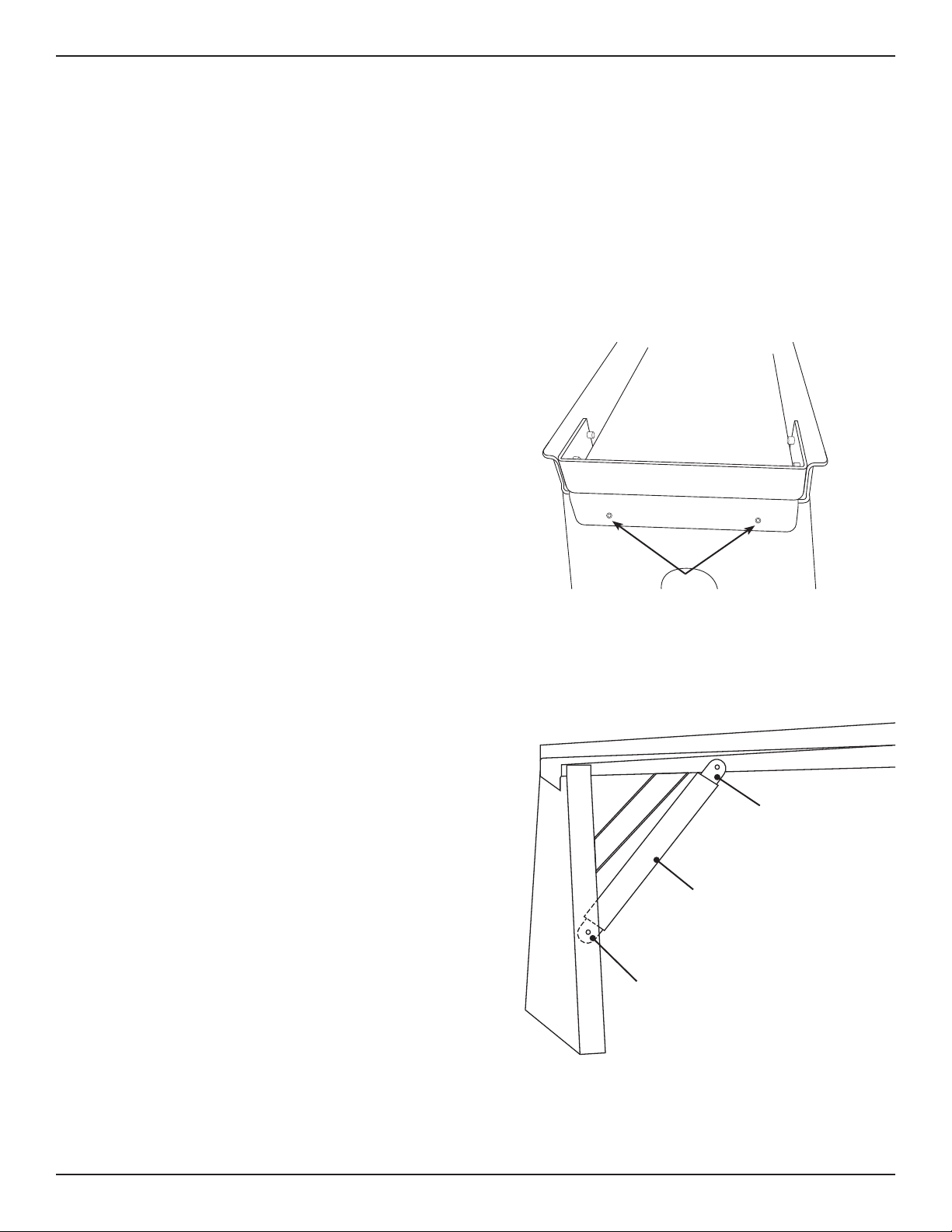
2.2.4 Parts Catcher
Place the parts catcher on the Beak at
the Head of the machine, just in front
of and under the Gate opening.
Locate eight ¾ in. button head screws,
nuts and washers from the hardware
bag. Insert the eight fasteners through
the slotted opening in the Parts
Catcher, aligning them with the holes in
the Beak.
Ensure the screw heads are on the
outside of the assembly and the nuts
and washers are on the inside. Thread
the nuts on and snug them down. Do
not tighten the nuts at this time.
Bend-Tech recommends enlisting a helper when assembling the Water Tray System.
Head of Machine
Parts Catcher
4 Bolts
per side
Leveling Feet
12 Bend-Tech Dragon
Material Coolant System Assembly
02
Material Coolant System Assembly Manual
2.2.5 Attach Water Tray to Parts Catcher
When assembling the coolant trays,
the face of the tray is placed behind
the parts catcher in the same fashion.
the parts catcher.
Use one of the support legs to support
the free end of the Water Tray. Use
four ¾ in. button head screws, nuts
and washers to attach the side tabs on
the coolant tray to the parts catcher.
Feed the screws through the side of the
coolant tray so the head of the screw is
inside the coolant tray and the nut and
washer are on the outside.
Use a punch or small Phillips head screwdriver to help align the mounting holes in the
Water Tray system.
Head of Machine
Tray 1
Support Leg
Beak
Parts Catcher
Parts Catcher
Tray 1
13Bend-Tech Dragon
Material Coolant System Assembly
02
Material Coolant System Assembly Manual
Locate one of the rollers from the parts
bag. Using two 1 in. button head screws,
nuts and washers, attach the roller on
the inside face of the coolant tray where
it connects to the parts catcher. Feed the
button head screw through the roller and
through the mounting holes in the Water
Tray and the parts catcher. Ensure the
roller is placed as far up as possible.
2.2.6 Water Tray System Assembly
Position the second coolant tray behind
second support leg to support the free end
of the second coolant tray.
mounting surface is on the outside of both
water trays. Align the four mounting holes
in the support leg with the holes on the
tabs on the second coolant tray.
Fasten the sides of the coolant trays and
support leg together using four 1 in. button
head screws, nuts and washers. Ensure
the heads of the screws are on the inside
of the water tray and the nuts and washers
are on the outside. Do not tighten.
Top View
Drain
Support Leg Brace
Support Leg
Tray or Parts
Catcher
Drain
Roller
Do not tighten any fasteners on the coolant tray assembly until all of the components
are connected.
14 Bend-Tech Dragon
Material Coolant System Assembly
02
Material Coolant System Assembly Manual
tight.
Repeat this process with the third coolant tray.
2.2.7 C-Bracket
Place the C-Bracket at the front end of Aluminum Tray No. 3. Align the mounting holes of the
third support leg with the holes in the
Water Tray and C-Bracket.
with the heads on the inside of the Water
Tray and the nuts and washers on the
outside of the support leg.
Below the C-Bracket, insert two ¾ in.
button head fasteners, with the heads on
leg and the nuts on the inside, to secure
leg.
2.2.8 Support Leg Braces
Starting at the front of the system, use (12)
¾ in. button head screws, washers and
nuts to attach the support leg braces to the
support legs and the coolant trays.
brace to the inside the of the support leg,
inserting the button head screws so the
head is on the outside of the support leg
and nut and washer are on the inside.
Attach the bent end of the support leg brace
to the outside of the coolant tray, feeding
the button head screw from the inside of the
coolant tray and the nut and washer are on
the outside.
Outside of Tray
(Bent End)
Support Leg Brace
Inside of Support
Leg (Flat End)
Tray 3
C-Bracket
fasteners
15Bend-Tech Dragon
Material Coolant System Assembly
02
Material Coolant System Assembly Manual
2.2.9 Finishing the Coolant Tray Assembly
braces. Tighten securely. Take care to position the rollers so they sit above the surface of the
coolant trays, adjusted as high as possible.
2.3 Water Tray Drain System
The material coolant system’s drain system collects water from the coolant trays, holds it in the
coolant system reservoir and recirculates
it back through the material.
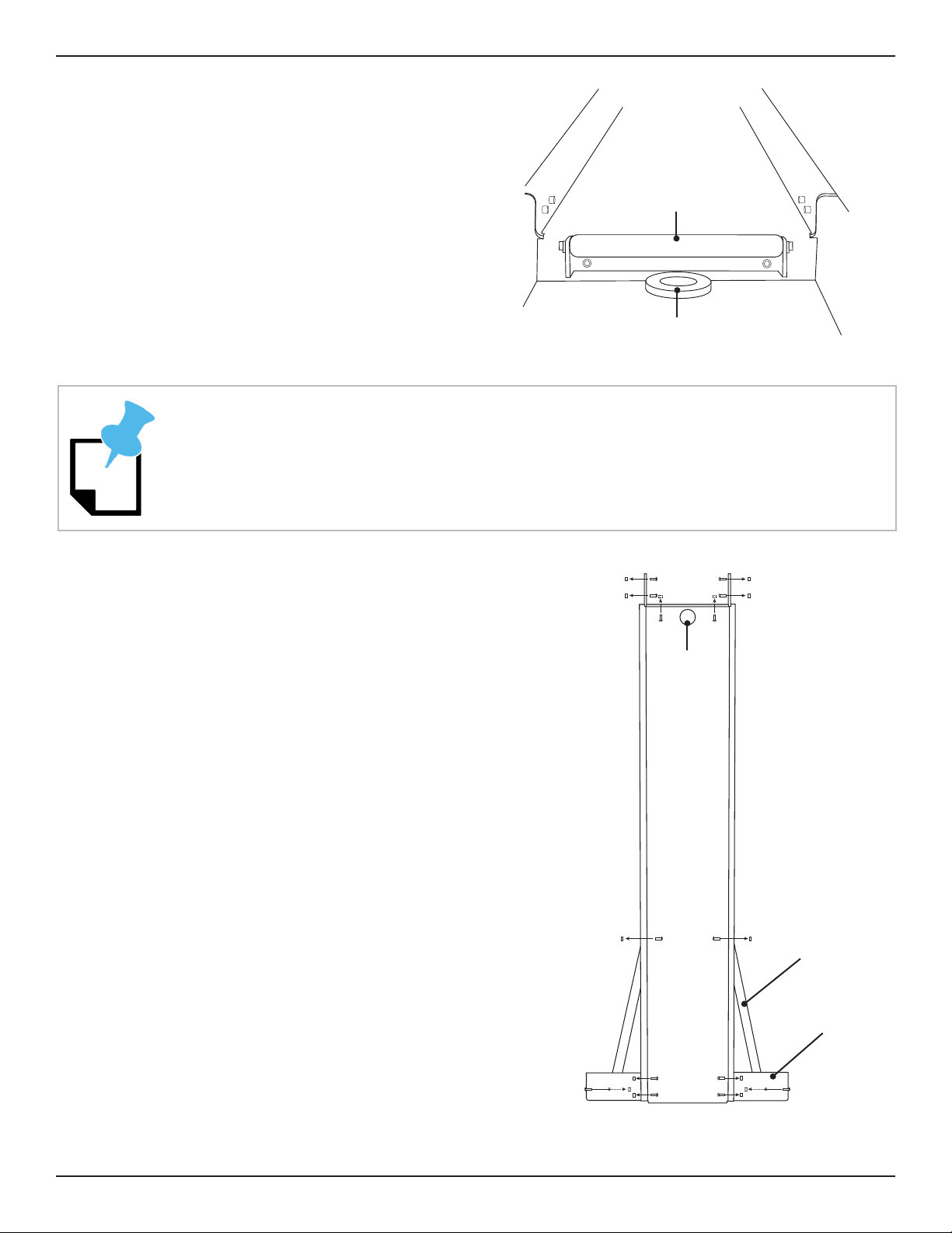
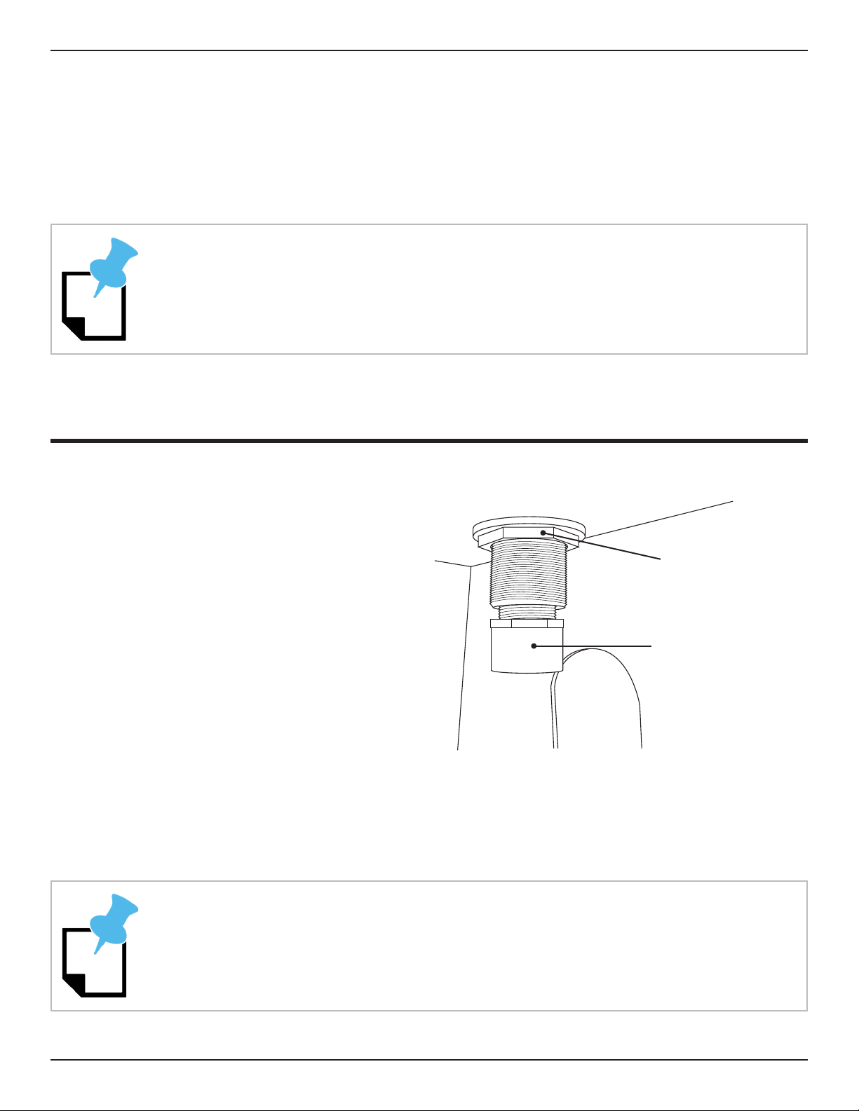
2.3.1 Bung Installation
Locate the four drain bungs in the PVC
parts bag. Remove the coupling nuts from
each drain bung. Insert a bung into the
drain hole in each coolant tray and in the
parts catcher. Thread the nuts back onto
each bung underneath the coolant tray
and tighten securely using a large channel
lock pliers. Locate the male/female
couplers in the PVC parts bag. Thread
one PVC male/female coupler into each
drain bung.
Also thread one PVC coupler into the bung inside the parts catcher. This will allow the parts
catcher to hold water to help cool parts.
Teon tape or plumber’s tape can help seal the male/female coupler in the drain bung.
Drain Bung
Male/Female
Coupler
When in use, the rollers should keep parts from resting on the bottom of the coolant
trays.
16 Bend-Tech Dragon
Material Coolant System Assembly
02
Material Coolant System Assembly Manual
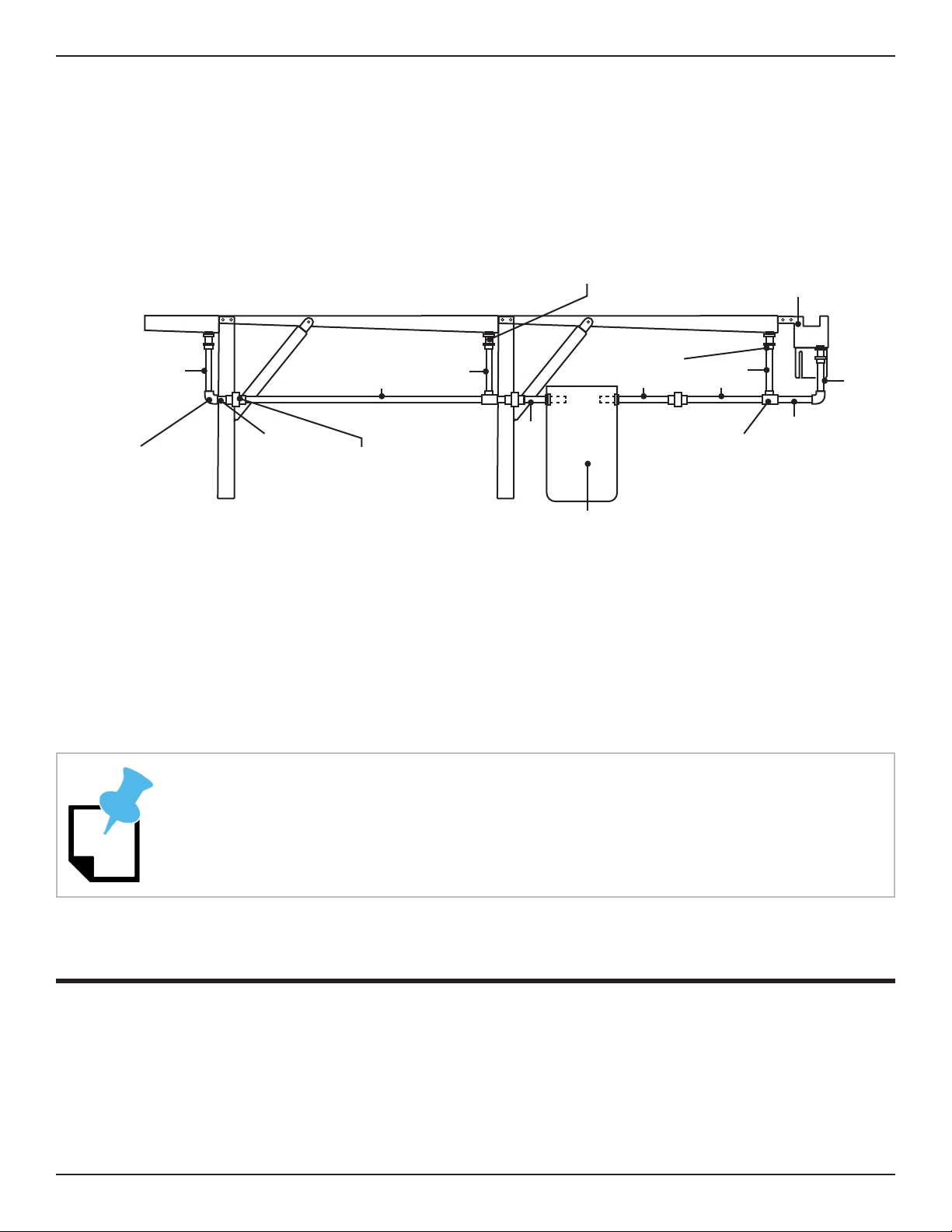
2.3.2 PVC Drain Installation
The PVC drain system is installed beginning at the parts catcher and then working to the end
of the trays. The PVC parts are numbered in order of installation. During this process the
Installer will also place and connect the coolant reservoir. Using PVC cement, install the parts
per diagram 2.3.3.
2.3.3 Tray System Drain Diagram
2.3.4 Placing the Cooling System Reservoir
Place the coolant reservoir according the diagram in section 2.3.3. Install the screens on the
drains feeding into the coolant reservoir. Secure using zip ties.
Fit the No. 5 and No. 6 PVC pieces through the grommets in the reservoir.
2.4 Water Pump
The material coolant system requires a water pump to be operational. Because customer
needs can vary, Bend-Tech does not supply a water pump with the coolant system. The
Customer will be required to supply a water pump to complete the coolant system. Refer to
Drain Bung
Coupler
Parts Catcher
Union Fitting
Elbow Fitting T Fitting
Cooling System
Reservoir
1
2
3
45
8
9
10
11
6
Depending on the size of the the water pump used, the pump may need to be placed
into the reservoir prior to connecting the reservoir to the rest of the PVC drain system.
17Bend-Tech Dragon
Material Coolant System Assembly
02
Material Coolant System Assembly Manual
2.4.1 Water Pump Requirements
2.4.2 Recommended Water Pump Specications
Voltage 120VAC
Running Amps 3.84
Horsepower .5
Volume 2500GPH
2.5 Hose System
The material coolant system uses hoses to transport water from the coolant reservoir back
through the material.
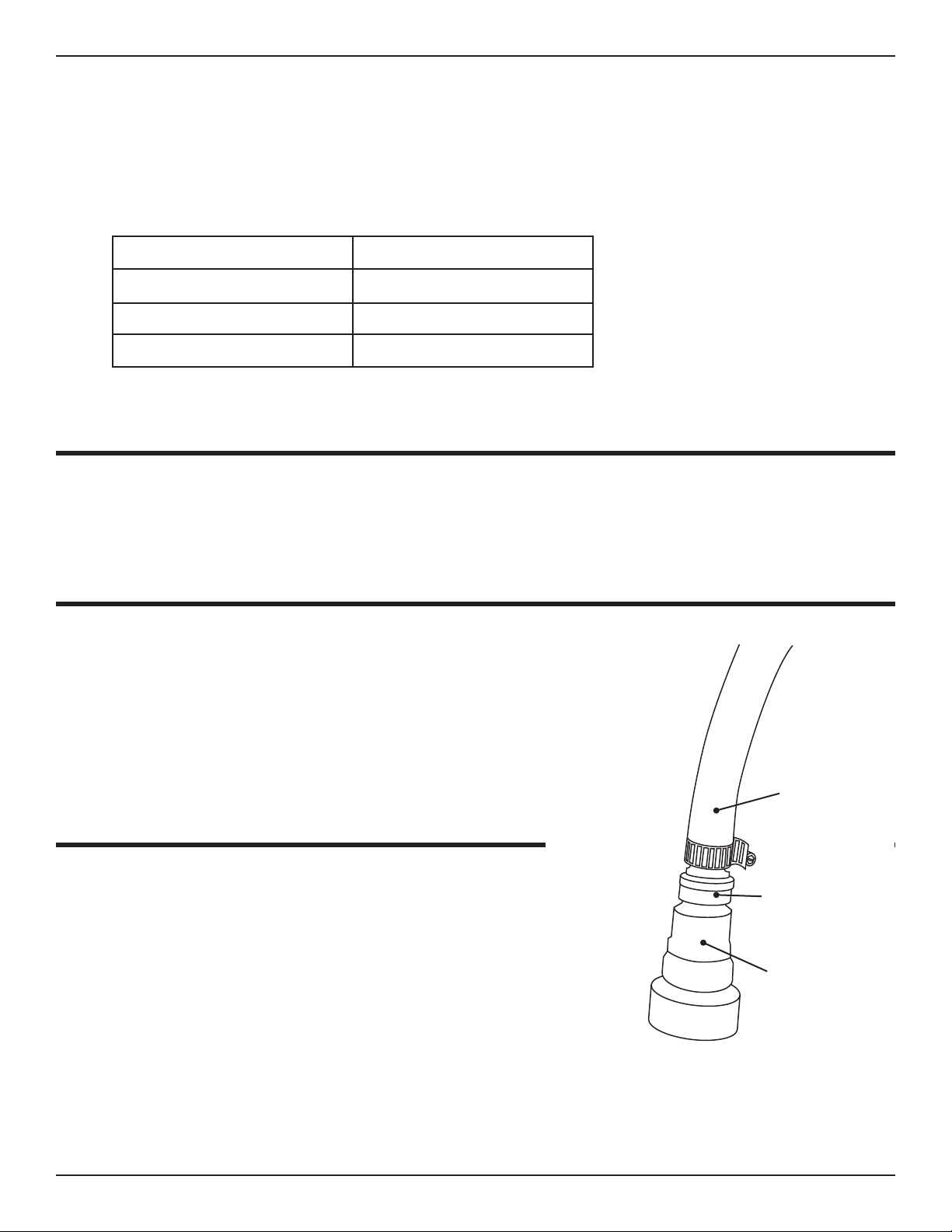
2.6 Connect the Pump
and attach to the water pump. Using a hose clamp
from the hose attachment bag, place the clamp
over the end of the long hose and slip the hose
securely.
2.7 Install the Water Pump
With the hose attached to the pump, set the pump
inside the coolant reservoir. Install the cover on the
coolant reservoir, routing the water pump power
cord and hose through the opening in the cover.
Attach the wireless remote-control outlet to the
water pump power cord, and then the yellow GFCI
power cable to the remote-control outlet.
Hose Clamp
Brass Barb Fitting
Water Pump Outlet
18 Bend-Tech Dragon
Material Coolant System Assembly
02
Material Coolant System Assembly Manual
2.8 Attaching the Hose to the Rail Beam
Locate six T-nuts and six ½ in. hex
screws from the hardware bag,
along with six cushion clamps. Loop
the cushion clamps around the hose,
spacing evenly at intervals along the
beam. Attach the cushion clamps to
the beam using the T-nuts and hex
screws.
2.9 Hose Reel Mount
Attach the hose reel mount to the Tail
of the machine. The mount bolts to the
outside of the last leg of the machine
in. socket and ratchet.
Hex Screw
Hose
Cushion Clamp
T-Nut

19Bend-Tech Dragon
Material Coolant System Assembly
02
Material Coolant System Assembly Manual
2.10 Hose Reel
four nyloc nuts in the hardware bag.
Position the hose reel in place on the
hose reel mount, aligning the four
hex bolts one at a time, with the head
on the hose reel side. Thread the nyloc
nuts on until they hit the nylon insert.
When all four bolts are in, tighten
socket.
Connect the water hose to the brass
connection on the side of the hose reel
and secure with a hose clamp.
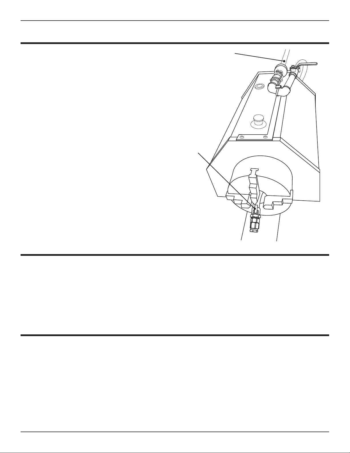
2.11 Trolley Hose Mount
Before attaching the hose mount to the front of
the trolley cover, locate the black rubber mat.
Remove the backing from the rubber mat and
stick it to the side of the trolley cover as shown in
the image. This will reduce physical wear of the
Remove the two screws at the front of the trolley
cover, just above the chuck. Place the trolley
hose mount on the trolley cover. Fasten to the
trolley cover using the two trolley cover screws.
The hose reel is heavy, enlist help during the mounting process.
Hose Mount
Intake Connection
Black Rubber Mat
20 Bend-Tech Dragon
Material Coolant System Assembly
02
Material Coolant System Assembly Manual
2.12 Connect the Hose
Pull the hose from the hose reel and hook the
ball valve assembly on the Hose Mount. Feed
the short section of hose through the back of the
trolley and through the chuck. The Plug Adapters
will be secured with the cam lock.
2.13 Leveling the Coolant Trays
to-side and front to back. Use a bubble level placed on the edges of the coolant trays to
wrench to turn the bottom nut on each leveling foot to adjust. Once level, tighten the top nut on
the leveling foot.
2.14 Sealing the Coolant Trays
Using the silicone sealant, place a bead of silicone around all gaps and seams in the coolant
before using the coolant system.
Feed short end
through the Chuck
Hose from Hose
Reel
Other manuals for Dragon mAchines
1
Table of contents
Other Bend-Tech Industrial Equipment manuals

Bend-Tech
Bend-Tech Dragon A400 User manual

Bend-Tech
Bend-Tech Dragon mAchines User manual

Bend-Tech
Bend-Tech Dragon A400 Installation guide

Bend-Tech
Bend-Tech Dragon A400 User manual

Bend-Tech
Bend-Tech Dragon User manual

Bend-Tech
Bend-Tech DRAGON A150 User manual

Bend-Tech
Bend-Tech Dragon A400 User manual

Bend-Tech
Bend-Tech Dragon A400 Installation guide

Bend-Tech
Bend-Tech Dragon A400 User manual

Bend-Tech
Bend-Tech Dragon A400 Installation and operation manual


