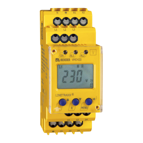
Bender RCM460Y User manual

1
Differenzstrom-
Überwachungsgeräte
Bestimmungsgemäße Verwendung
Die Differenzstrom-Überwachungsgeräte RCM460Y und
RCM465Y überwachen den Differenzstrom (AC, DC pulsierend) in
geerdeten 2-, 3- oder 4-Leiter-Systemen (TN-/TT-Systemen).
Ebenso können sie zur Stromüberwachung von im Normalfall
stromlosen Einzelleitern (z.B. N-, PE-Leiter) eingesetzt werden.
Aufgrund des einstellbaren Ansprechwertes von 30 ... 300 mA
sind sie für kleinere Anlagen und Verteilungen, einzelne Verbrau-
cher oder zur Überwachung von Einzelleitern geeignet. Durch die
Messwerterfassung über einen Differenzstromwandler sind die
Geräte nahezu unabhängig von Laststrom und Nennspannung
der zu überwachenden Anlage. In Verbindung mit einem exter-
nen Differenzstromwandler können sie auch für Stromschienen-
Systeme eingesetzt werden.
In der Ausführung RCM465Y... ist der Differenzstromwandler ø 26
mm im Gerät integriert, während für die Baureihe RCM460Y ex-
terne Differenzstromwandler Typ W, WR und WS eingesetzt wer-
den (siehe Tabelle Differenzstromwandler).
Sicherheitshinweise allgemein
Montage, Anschluss und Inbetriebnahme nur durch Elektrofach-
kraft!
Beachten Sie unbedingt:
●die bestehenden Sicherheitsvorschriften und
●das beiliegende Blatt "Wichtige sicherheitstechnische Hin-
weise für BENDER-Produkte".
Funktionsbeschreibung
Der gewünschte Ansprechwert I∆nist stufenlos einstellbar. Über-
schreitet der gemessene Differenzstrom den eingestellten An-
sprechwert, so leuchtet die ALARM-LED auf und das Alarmrelais
schaltet. Eine Ansprechverzögerung ist einstellbar.
Bedienelemente
Beide Geräte haben die gleichen Bedienelemente. Lediglich die
Anschlüsse sind unterschiedlich
Abb. 1: Bedienelemente RCM460Y und RCM465Y
Residual Current Monitors
Intended use
RCM460Y and RCM465Y are residual current monitors which con-
tinuously monitor and indicate the residual current (AC, DC pul-
sating) in earthed two, three or four-wire systems (TN/TT
systems). They can also be used for current monitoring of single
conductors such as neutral or PE conductors, which in normal op-
eration carry no current.
Thanks to the adjustable response value of 30...300 mA they are
suitable for small installations and distributions, individual elec-
trical loads or for single conductor monitoring. The measuring
values are detected via residual current transformers, therefore
the devices are nearly independent of nominal voltage and load
current of the system to be monitored. In combination with a re-
mote residual current transformer they are also suitable for bus-
bar systems.
The RCM465Y... utilizes an internal residual current transformer
(ø 26 mm). RCM460Y utilizes an external residual current trans-
former of the W, WR and WS type (see table "External residual cur-
rent transformers").
Safety information
Installation, connection and commissioning of electrical equip-
ment shall only be carried out by qualified electricians:
Particular attention shall be paid to:
●the current safety regulations and
●the enclosed sheet "Important safety instructions for
BENDER products".
Function
The appropriate response value I∆nis steplessly adjustable. When
the residual current exceeds the set response value, the ALARM
LED lights up and the alarm relay switches. A response delay time
is adjustable.
Operating elements
Both devices are equipped with the same operating elements.
Only the connections are different.
Figure 1: Operating elements of RCM460Y and RCM465Y
RCM460Y / RCM465Y
401001 / 02.03
Deutsch English

2401001 / 02.03
RCM460Y / RCM465Y
Legend to operating elements
1 TEST button
2 ON LED (green) lights up indicating device in operation.
3 ALARM LED (yellow) lights up when the response value of
the residual current is exceeded and after the expiry of
the response time.
LED lights also in case of CT interruption (RCM460Y only).
4 For setting the maximum time delay t/s for residual cur-
rent measurement in the range of 0 ... 1 second.
5 Setting the residual operating current to 30 mA ... 300 mA.
6 Symbol in compliance with DIN EN 62020: RCM type A for
residual alternating currents and pulsating direct cur-
rents.
Installation and connection.
Installation
The device is suited for:
• mounting into standard distribution panels acc. to DIN 43 871
• DIN rail mounting acc. to IEC 60715
• or screw mounting.
Dimension diagram
Figure 2: Dimension diagram RCM460Y and RCM465Y,
all dimensions in mm
Prior to installation and before work activities are
carried out on the connecting cables, make sure that
the mains power is disconnected.
Failure to comply with this safety information may
cause electric shock to personnel.
Furthermore, substantial damage to the electrical in-
stallation and destruction of the device can occur.
Legende der Bedienelemente
1Testtaste
2 ON-LED (grün) leuchtet, wenn Gerät im Betrieb ist.
3 LED „ALARM“ (gelb) leuchtet wenn der Ansprechwert des
Differenzstroms und die Ansprechzeit überschritten sind.
LED leuchtet bei Wandlerunterbrechung (nur RCM460Y)
4 Ansprechverzögerung t/s für Differenzstrommessung im
Bereich von 0 ... 1 Sekunde einstellen.
5 Ansprechwert des Differenzstroms im Bereich von
30 mA ... 300 mA einstellen.
6 Symbol nach DIN EN 62020: RCM Typ A für Wechselfehler-
ströme und pulsierende Gleichfehlerströme
Montage und Anschluss.
Montage
Das Gerät ist für folgende Einbauarten geeignet:
• Installationsverteiler nach DIN 43 871 oder
• Schnellmontage auf Hutprofilschiene nach IEC 60715
• oder Schraubmontage.
Maßbild
Abb. 2: Maßbild RCM460Y und RCM465Y,
alle Maße in mm
Stellen Sie vor Einbau des Gerätes und vor Arbeiten
an den Anschlüssen des Gerätes sicher, dass die Anla-
ge spannungsfrei ist.
Wird dies nicht beachtet, so besteht für das Personal
die Gefahr eines elektrischen Schlages.
Außerdem drohen Sachschäden an der elektrischen
Anlage und die Zerstörung des Gerätes.

3
401001 / 02.03
RCM460Y /
Anschluss
Schießen Sie das RCM wie folgt an. Beachten Sie dabei das An-
zugsdrehmoment für die Klemmschrauben der Anschlüsse: 0,5 ...
0,6 Nm (4,3 ... 5,3 lb-in).
1. Anschluss der Versorgungsspannung
Verbinden Sie die Anschlussklemmen des Gerätes mit der
erforderlichen Versorgungsspannung US(Siehe Typen-
schild). Sichern Sie die Zuleitung mit einer Sicherung 6 A
ab.
2. Anschluss des zu überwachenden Netzes
Achtung: PE-Leiter nicht durch den Differenzstrom-
wandler führen!
RCM460Y:
– Führen Sie die Wandlerleitungen k und l durch den im
Lieferumfang enthaltenen EMV-Absorber. Der Absorber
muss mit dem beiliegenden Kabelbinder unmittelbar
vor den Klemmen k und l des RCMs befestigt werden.
– Schließen Sie den externen Differenzstromwandler an
die Klemmen k und l an.
– Führen Sie die zu überwachenden Leiter durch den Dif-
ferenzstromwandler. Beachten Sie die Hinweise im Bei-
packzettel des Differenzstromwandlers.
Anschluss zum Differenzstromwandler:
Einzeldrähte 2 x 0.75 mm2max.1 m
Einzeldrähte verdrillt 2 x 0.75 mm2max.10 m
Schirmleitung* 2 x 0.75 mm2max. 25 m
* Schirm einseitig in der Nähe des RCM460Y an PE
RCM465Y:
– Führen Sie die zu überwachenden Leiter durch den ein-
gebauten Differenzstromwandler.
3. Anschluss an das Alarmrelais
Schließen Sie Komponenten, die bei auftretenden Alar-
men geschaltet werden sollen, an die Ausgangsklemmen
des Alarmrelais an. Beachten Sie die von dem Relais maxi-
mal schaltbaren Spannungen und Ströme (siehe Typen-
schild)
Connection
Connect the RCM as described below. The tightening torque for
the terminal screws is : 0.5 ... 0.6 NM (4.3 ... 5.3 lb-in).
1. Connection to the supply voltage:
Connect the connecting terminals of the device to the
required supply voltage US(see nameplate). A 6 A fuse is
recommended for short-circuit protection.
2. Connection to the system to be monitored:
Note: Do not pass the PE conductor through the resi-
dual current transformer!
RCM460Y:
-Connect the CT connecting lead through the EMC absor-
ber.The absorber has to be fixed directly before the termi-
nals k and l of the RCM by using the accompanying cable
ties.
-Connect the external residual current transformer to the
terminals k and l.
-Lead the conductors to be monitored through the resi-
dual current transformer. Observe the instructions in the
residual current transformer application note.
Residual current transformer connection:
single wires 2 x 0.75 mm21 m
twisted pair 2 x 0.75 mm210 m
screened cable* 2 x 0.75 mm225 m
* Screen on one side connected to PE close to the RCM460Y.
RCM465Y:
-Lead the conductor to be monitored through the internal
residual current transformer.
3. Connection to the alarm relay:
Connect the devices to be activated in the event of an
alarm to the output terminals of the alarm relay. Refer to
the nameplate for the maximum voltages and currents the
relay is able to switch.

4401001 / 02.03
RCM460Y / RCM465Y
.
Abb. 3: Anschlussbild
Legende zum Anschlussbild
USVersorgungsspannung
F Kurzschlussschutz Versorgungsspannung.
Empfehlung: 6 A Sicherung
CT Externe Differenzstromwandler für RCM460Y.
Siehe Tabelle „Externe Differenzstromwandler“.
Anschlüsse:
A1, A2 Anschluss der Versorgungsspannung Us.
11, 12, 14 freier Wechsler schaltet im Alarmfall. Ein Alarm er-
folgt bei Erreichen des Ansprechwertes und nach Ablauf
der Ansprechzeitverzögerung.
Das RCM460Y meldet auch bei Unterbrechung des exter-
nen Differenzstromwandlers einen Alarm.
k, l Nur RCM460Y: Anschluss Differenzstromwandler
EMI-Absorber Führen Sie die Wandlerleitungen k und l durch
den im Lieferumfang enthaltenen EMV-Absorber. Der Ab-
sorber muss mit dem beiliegenden Kabelbinder unmittel-
bar vor den Klemmen k und l des RCMs befestigt werden.
Inbetriebnahme
1. Kontrollieren Sie vor der Inbetriebnahme den ordnungs-
gemäßen Anschluss des Gerätes .
2. Meldet das RCM bei der Inbetriebnahme sofort einen Feh-
ler, so überprüfen Sie den nachgeschalteten Betriebs-
stromkreis und daran angeschlossene Verbraucher auf
Isolationsfehler.
Führen Sie eine Funktionsprüfung mittels eines RCD-
Prüfgerätes durch.
Figure 3: Wiring diagram
Legend to wiring diagram
USSupply voltage
F Short-circuit protection supply voltage:
a 6 A fuse is recommended.
CT External residual current transformers for RCM460Y
See table "External residual current transformers".
Connections:
A1, A2 Connection supply voltage Us.
11, 12, 14 voltage free changeover contacts, trips in case
of alarm. An alarm occurs when the response value is ex-
ceeded and after the response delay time has expired.
The RCM460Y also issues an alarm in case of residual cur-
rent transformer interruption.
k, l RCM460Y only: Connection residual current transformer
EMI absorber The CT connecting leads k and l must be led
through the EMI absorber. The absorber has to be fixed
directly before the terminals k and l by using the accom-
panying cable ties.
Commissioning
1. Prior to commissioning, check proper connection of the
device. .
2. If an RCM signals a fault immediately after commissioning,
check the operating circuit and the connected loads
downstream the devices for insulation faults.
Carry out a functional test using an RCD test device.

5
401001 / 02.03
RCM460Y /
3. Nehmen Sie folgende Einstellungen passend zur Anlage
vor:
– Ansprechbereich auswählen
– Zeitverzögerung einstellen
4. Führen Sie einen Test durch:
– Taste „Test“ betätigen: Ein Alarm wird erkannt
Die Funktionsprüfung sollte regelmäßig in etwa monatlichem
Abstand mit der Taste „Test“ durchgeführt werden.
Bei Betätigung der Taste „Test“ muss die Alarm-LED leuchten und
das Melderelais muss schalten. Danach erfolgt automatisch der
Reset.
Außer der Funktionsprüfung der Differenzstromüberwachung ist
die Wirksamkeit der Schutzmaßnahme in der Installation ent-
sprechend den geltenden Errichtungsbestimmungen zu prüfen.
Bedienen
Ansprechwert und Ansprechzeit können erneut eingestellt wer-
den, wenn Änderungen an der Anlage erfolgt sind.
Die LED „ALARM“ leuchtet, wenn ein Alarm aufgetreten ist. Der
Alarm wird nicht gespeichert.
Wird die TEST-Taste gedrückt, so wird ein automatischer Test
durchgeführt. Es kann nur ein Test durchgeführt werden, wenn
zuvor keine Fehlermeldung vorhanden war.
Ein Test-Differenzstrom wird simuliert, nach Ablauf der An-
sprechzeit wird ein Alarm erkannt, das Alarmrelais schaltet, und
die LED „ALARM“ leuchtet. Die Alarmmeldung wird nicht gespei-
chert.
Überwachung externer Differenzstromwandler
Der Anschluss externer Differenzstromwandler an das RCM460Y
wird überwacht. Bei nicht angeschlossenem Differenzstrom-
wandler oder Unterbrechung der Wandlerverbindung leuchtet
die LED „ALARM“ und das Alarmrelais schaltet. Ein Kurzschluss
des Differenzstromwandlers wird nicht erkannt.
Störungen – Das RCM hat einen Alarm gemeldet
Meldet das RCM einen Alarm, sind der nachgeschaltete Betriebs-
stromkreis und daran angeschlossene Verbraucher auf Isolations-
fehler zu überprüfen. Durch die Wahl des Ansprechwertes und
der Zeitverzögerung kann das RCM auf den Vorfehlerstrom der
Anlage angepasst werden.
Mögliche Fehlerursachen:
●Isolationsfehler auf der Verbraucherseite. (L-PE) (L-Erde)
●Verbindung zwischen Neutralleiter und Schutzleiter auf
der Verbraucherseite
●Hohe kapazitive Ableitströme von Verbrauchsgeräten und
Leitungen (z. B. durch EMV-Filter)
●EMV-Filter oder Überspannungsableiter vor dem Diffe-
renzstromwandler installiert
●Schaltüberspannungen. Sie entstehen vornehmlich durch
im Einschaltmoment beginnende Ladevorgänge. Diese
entstehen, wenn z. B. Betriebsmittel mit Kondensatorbe-
schaltung oder Kabelstrecken eingeschaltet werden. Auch
von Körperschlüssen können sie verursacht werden.
●Isolationsfehler zwischen N-Leiter und Gehäuse (SK I)
●Verbindung zwischen den Außenleitern der gleichen
Phase hinter verschiedenen RCMs
3. Make the following settings suitable for the conditions in
your installation :
– select the response range
– set the time delay
4. Perform a test:
– Press the TEST button: an alarm is recognized
The functional test is recommended to be carried out once a
month by pressing the TEST button.
Pressing the TEST button, must cause the alarm LED to light and
the alarm relay to switch. After the test, the device automatically
resets.
In addition to the functional test of the residual current monito-
ring, also the effectiveness of the protective measures in the in-
stallation according to the current regulations for the erection of
electrical equipment are to be checked.
Operation
A new response value and response time can be set after modifi-
cations have taken place in the electrical installation.
The ALARM LED lights when an alarm occurs. The alarm will not
be stored.
By pressing the TEST button, a test is automatically carried out.
The test cannot be carried out when a fault message exists.
The test residual current is being simulated, after the expiry of the
response time, an alarm is recognized, the alarm relay switches,
and the ALARM LED lights. The alarm message will not be stored.
Monitoring external residual current transformers
The connection of external residual current transformers to the
RCM460Y is monitored. When a residual current transformer is
not connected or the CT connection is interrupted, the ALARM
LED lights and the alarm relay switches. A short circuit in the resi-
dual current transformer will not be recognized.
Faults - The RCM issues an alarm
If the RCM signals an alarm, the operating circuit and the loads
connected to it downstream the RCM are to be checked for insu-
lation faults. By selecting the appropriate response value and the
time delay, the RCM can be adapted to the fault current existing
in the electrical installation during normal conditions.
Possible faults:
●Insulation fault on the load side (L-PE) (L-earth)
●Connection between the neutral conductor and PE con-
ductor on the load side
●High capacitive leakage currents of loads and connecting
leads (e.g. by EMC filters))
●EMC filters and surge voltage protectors installed
upstream the residual current transformer
●Switching overvoltages. Frequently occurring when load
operations are being started. These overvoltages can be
caused by switching on electrical equipment including
capacitors and long cable runs. They can also be caused by
short circuits.
●Insulation fault between the neutral conductor and the
enclosure (protection class I)
●Connection between phase conductors of the same phase
downstream various RCMs

6401001 / 02.03
RCM460Y / RCM465Y
Normen
DIN EN 62020 (VDE 0663): 1999-07
„Elektrisches Installationsmaterial - Differenzstrom-Überwa-
chungsgeräte für Hausinstallationen und ähnliche Verwendun-
gen (RCMs) (IEC 62020:1998); Deutsche Fassung EN 62020:1998“
RCM460Y und RCM465Y sind Differenzstrom-Überwachungsge-
räte des Typs A.
Technische Daten
Isolationskoordination nach IEC 60664-1:
Bemessungsspannung AC 250 V
Bemessungs-Stoßspannung/Verschmutzungsgrad 4 kV/3
Spannungsbereiche
Versorgungsspannung US siehe Typenschild / Bestellangaben
Arbeitsbereich von US0,85 ... 1,1 x US
Frequenzbereich von Us50 ... 400 Hz
Eigenverbrauch RCM460Y max. 2,6 VA
Eigenverbrauch RCM465Y max. 1,5 VA
Messkreis/Ansprechwerte
Differenzstromwandlertyp extern Serie W..., WR..., WS...
Bürde 180 Ω
Differenzstromwandlerdurchmesser intern 26 mm
Auslösecharakteristik nach DIN EN 62020 Typ A
Bemessungs-Auslösedifferenzstrom I∆neinstellbar 30 mA ... 300 mA
Bemessungsfrequenz 40...400Hz
Ansprechabweichung +0 ... -25 % vom Ansprechwert
Hysterese ca. 25 % vom Ansprechwert
Ansprechzeit tan bei 1 x I∆n / 5 x I∆n(tv = 0s) < 300 ms / < 40 ms
Ansprechverzögerung tVeinstellbar 0...1 s
Ansprechverzögerung ±20 %
Anzahl Messkanäle 1
Anzeigen
ON-LED, Melde-LED Ja
Eingänge/Ausgänge
Prüf- / Löschtaste potentialfrei Prüftaste intern
Schaltglieder
Schaltglieder-Melderelais 1 x 1 Wechsler
Arbeitsweise Arbeitsstrom
Elektrische Lebensdauer 12000 Schaltspiele
Kontaktbemessungsspannung AC 250 V / DC 300 V
Einschaltvermögen AC/DC 5 A
Ausschaltvermögen bei
AC 230 V und cos phi = 0.4 2 A
DC 220 V und L/R = 0,04 s 0,2 A
Allgemeine Daten
Produktnorm DIN EN 62020:1999-07
EMV-Störfestigkeit nach DIN EN 62020/A1
EMV-Störaussendung nach DIN EN 62020/A1
Schockfestigkeit IEC 60068-2-27 (Gerät in Betrieb) 15g /11 ms
Dauerschocken IEC 60068-2-29 (Transport) 40g/6 ms
Schwingungsbeanspruchung IEC 60068-2-6 (Gerät in Betrieb) 1g/10-150 Hz
Schwingungsbeanspruchung IEC 60068-2-6 (Gerät außer Betrieb) 2g/10-150Hz
Umgebungstemperatur, bei Betrieb -10 ºC ... +55 ºC/263 K...328 K
Umgebungstemperatur, bei Lagerung -40 ºC ... +70 ºC/233 K ...343 K
Klimaklasse nach DIN IEC 60721-3-3 3K5
Betriebsart Dauerbetrieb
Einbaulage beliebig
Anschlussart / Leitung Reihenklemmen
Anzugsmoment 0,5...0,6 Nm / 4,3...5,3 lb-in
Standards
DIN EN 62020 (VDE 0663): 1999-07
IEC 62020 (VDE0663): 1998-08
"Electrical accessories – Residual current monitors for household
and similar uses (RCMs)".
RCM460Y and RCM465Y are residual current monitors of type A.
Technical data
Insulation coordination according to IEC 60664-1:
Rated voltage AC 250 V
Rated impulse voltage/pollution degree 4 kV/3
Voltage ranges
Supply voltage US see nameplate / ordering details
Operating range of US0.85 ... 1.1 x US
Frequency range of Us50 ... 400 Hz
Max. power consumption RCM460Y 2.6 VA
Max. power consumption RCM465Y 1.5 VA
Measuring circuit/response values
Type of external residual current transformer W...,WR..., WS...
Load 180 Ω
Diameter of internal residual current transformer 26 mm
Operating characteristics according to DIN EN 62020 type A
Rated residual operating current I∆n, adjustable 30 mA ... 300 mA
Rated frequency 40...400Hz
Relative percentage error +0 ... -25 %
Hysteresis approx. 25 %
Response time tan at 1 x I∆n / 5 x I∆n(tv = 0 s) < 300 ms / < 40 ms
Response delay tV, adjustable 0...1 s
Time delay ±20 %
Number of measuring channels 1
Displays
ON LED, alarm LED yes
Inputs/outputs
Test / reset button, voltage free internal test button
Switching elements
Switching elements alarm relay 1 x 1 changeover contact
Operating principle N/Ooperation
Electrical endurance / number of cycles 12000
Rated contact voltage AC 250 V / DC 300 V
Limited making capacity AC/DC 5 A
Limited breaking capacity
AC 230 V and cos phi = 0.4 2 A
DC 220 V and L/R = 0.04 s 0.2 A
General data
Product standard DIN EN 62020:1999-07
EMC immunity according to DIN EN 62020/A1
EMC emission according to DIN EN 62020/A1
Shock resistance IEC 60068-2-27 (device in operation) 15g /11 ms
Bumping IEC 60068-2-29 (during transport) 40g/6 ms
Vibration resistance IEC 60068-2-6 (device in operation) 1g/10-150Hz
Vibration resistance IEC 60068-2-6 (device out of operation) 2g/10-150Hz
Ambient temperature, during operation -10 ºC ... +55 ºC/263 K...328 K
Storage temperature range -40 ºC ... +70 ºC/233 K ...343 K
Climatic category according to DIN IEC 60721-3-3 3K5
Operating mode continuous operation
Position any position
Connection screw terminals
Tightening torque 0.5...0.6 Nm / 4.3...5.3 lb-in

7401001 / 02.03
RCM460Y / RCM465Y
Cross sectional area of connecting cable
rigid / flexible 0.2 ... 4 mm2/ 0.2 ... 2.5 mm2
Flexible with ferrules without/with plastic collar 0.25 ... 2.5 mm2
Conductor sizes (AWG) 24-12
Degree of protection, internal components (DIN EN 60529) IP30
Degree of protection, terminals (DIN EN 60529) IP20
Enclosure / dimension diagram X460 / X465
Screw fixing 2 x M4
DIN rail mounting according to IEC 60715
Installation into standard distribution panels acc. to DIN 43871
Flammability class UL94V-0
Weight approx. 180/190 g
Modified versions
There will only be a label in this field if the RCM is different from
the standard version.
Ordering details
* The values marked with an asterisk are absolute values of the
voltage range
Anschlussvermögen
Starr / flexibel 0,2 ... 4 mm2/ 0,2 ... 2,5 mm2
Flexibel mit Andernendhülse ohne/mit Kunststoffhülse 0,25 ... 2,5 mm2
Leitergrößen (AWG) 24-12
Schutzart Einbauten (DIN EN 60529) IP30
Schutzart Klemmen (DIN EN 60529) IP20
Gehäusetyp / Massbild X460 / X465
Schraubbefestigung 2 x M4
Schnellbefestigung auf Hutprofilschiene nach IEC 60715
Einbau in Installationsverteiler nach DIN 43871
Entflammbarkeitsklasse UL94V-0
Gewicht ca. 180/190 g
Abweichende Ausführungen
Dieses Feld ist nur beklebt, falls Änderungen gegenüber der Stan-
dardausführung des Gerätes vorgenommen wurden. In diesem
Fall ist ein weiterer Modifikationsaufkleber am Gerät angebracht
.
Bestellangaben
* Absolutwerte des Spannungsbereiches
Typ
Type
Versorgungsspannung Us
Supply voltage Us
Ansprechwert
Response value
Art.-Nr.
Art.No.
RCM460Y AC 230 V 30..300 mA B 94 012 022
RCM460Y-13 AC 90-132 V * 30..300 mA B 94 012 031
RCM460Y-71 AC 230 V 10..100 mA B 94 012 044
RCM460Y-7113 AC 90-132 V * 10..100 mA B 94 012 046
RCM465Y AC 230 V 30..300 mA B 94 012 023
RCM465Y-11 AC 24 V 30..300 mA B 94 012 048
RCM465Y-13 AC 90-132 V * 30..300 mA B 94 012 033
RCM465Y-71 AC 230 V 10..100 mA B 94 012 049
RCM465Y-7113 AC 90-132 V * 10..100 mA B 94 012 045

8
401001 / 02.03
RCM460Y /
Londorfer Str. 65 35305 Grünberg Fax: +49 (0)6401-807-259 Internet: http://www.bender-de.com
Postfach 1161 35301 Grünberg
Alle Rechte vorbehalten.
Nachdruck und Vervielfältigung
nur mit Genehmigung des Herausgebers.
Technische Änderungen vorbehalten!
All rights reserved.
Reprinting and duplicating
only by permission of publisher.
Right to technical modifications reserved!
©2003 BENDER Germany
External residual current transformers
Technical data: refer to residual current transformer application
note
Externe Differenzstromwandler
Technischen Daten: siehe Beipackzettel zum Differenzstrom-
wandler
Typ
Type
Innenmaß [mm]
Internal diameter
Art.-Nr.
Art. No.
W0-S15 ø 14,5 B 911 753
W1-S35 ø 35 B 911 731
W2-S70 ø 70 B 911 732
W3-S105 ø 105 B 911 733
W4-S140 ø 140 B 911 734
W5-S210 ø 210 B 911 735
WR70x175S 70 x 175 B 911 738
WR115x305S 115 x 305 B 911 739
WR150x350S 150 x 350 B 911 740
WR200x500S 200 x 500 B 911 763
WS50x80S 50 x 80 B 911 741
WS80x80S 80 x 80 B 911 742
WS80x120S 80 x 120 B 911 743
WS80x160S 80 x 160 B 911 755
This manual suits for next models
1
Table of contents
Other Bender Control System manuals