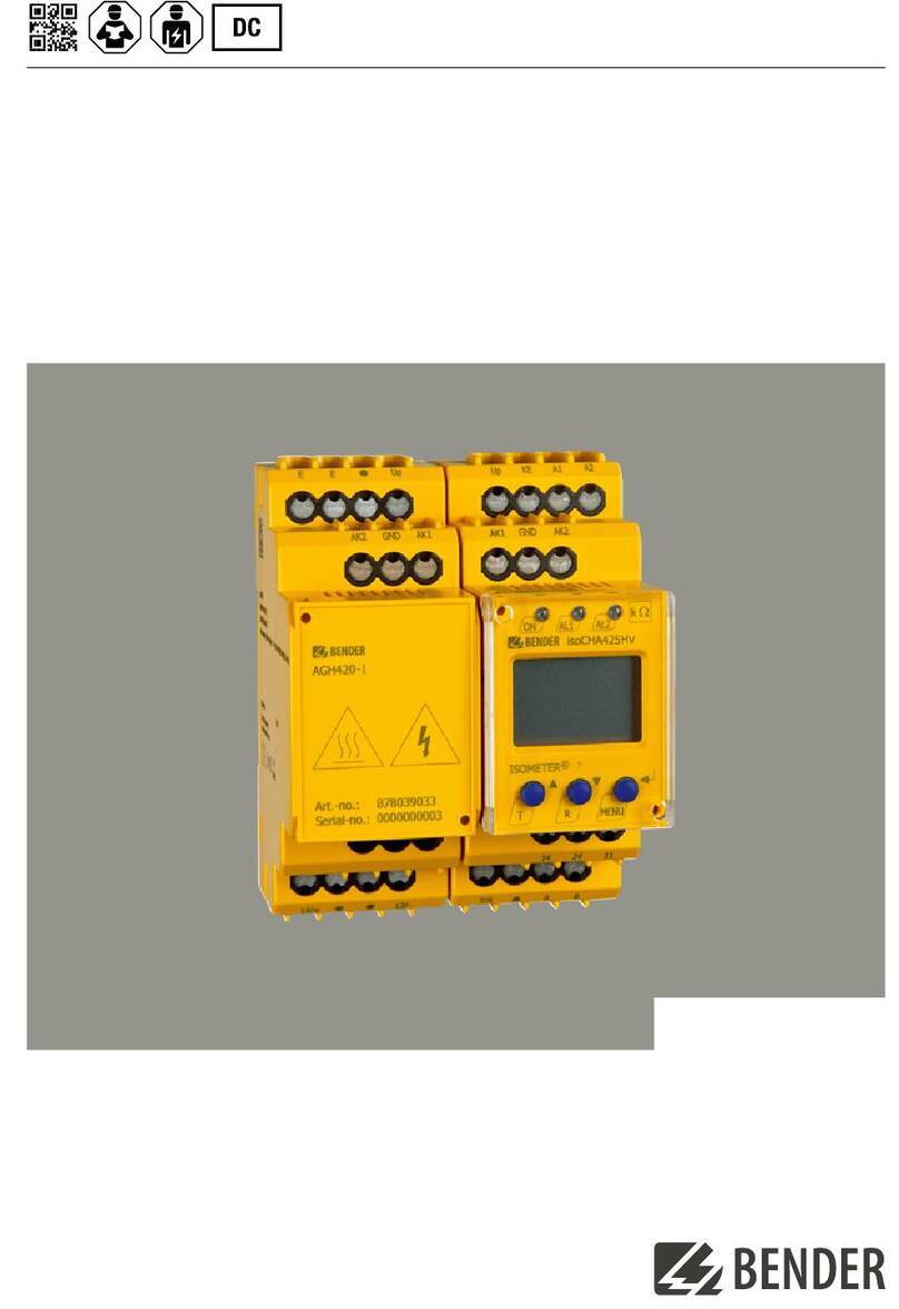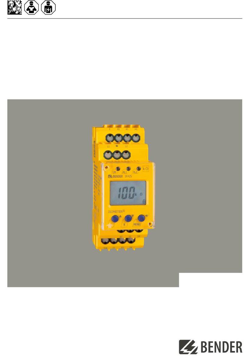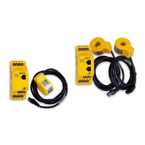
ISOMETER® isoPV425
with AGH420 coupling device
'FAC'), the device must be repaired. After the fault has been eliminated, the alarm relays switch back either
automatically or when the reset button is pressed. The self test can take a few minutes.
2.3.3.1 Automatic self test
In the factory setting a self test is carried out when the supply voltage Us is connected and after that every 24 h.
This cycle can be adjusted: off, 1 h, 24 h (see chapter 4. ).
The self test can be suppressed for the device start so that the device can enter the measurement mode more
quickly. To this end, set the parameter 'S.Ct = off' in the menu 'SEt'.
2.3.3.2 Manual self test
The manual self test is started by pressing the external test/reset button or the test button 'T' on the device for
˃ 1.5 s. Holding the test button 'T' also shows all display elements.
2.3.3.3 Connection monitoring
Connection monitoring, activated by the self test, checks the connections of terminals 'E' and 'KE' to the
protective earth conductor (PE). When an error is detected, the message device error ('Err') will be signalled
and the error code 'E.01' appears on the display.
The system connection monitoring checks the connection of terminals 'L1/+' and 'L2/–' to the system to be
monitored. When an interruption or a high-resistance connection between L1/+ and L2/– is detected via the
internal resistance of the system, the device error ('Err') is signalled and the error code 'E.02' appears on the
display. Since a test of the system connection may take considerable time due to system disturbances or may
even provide incorrect results, the system connection monitoring can be disconnected using the parameter
'nEt' in the 'SEt' menu.
2.3.4 Malfunction
The device checks some of its functions continuously during operation. If a fault is detected, the device
error ('err') will be signalled, 'E.xx' appears on the display as an identifier for error type xx, and the LEDs
'ON'/'AL1'/'AL2' will flash.
Please contact Bender Service, if the error occurs again after the device has been restarted or the factory
settings have been restored.
2.3.5 Signalling assignment of the alarm relays K1/K2
The notifications for 'device error', 'insulation fault', 'undervoltage/overvoltage fault', 'device test' and 'device
start with alarm' can be assigned to the alarm relays via the 'out' menu.
An insulation fault is indicated by the messages '+R1', '–R1', '+R2' and '–R2'. Messages '+R1' and '+R2' indicate
an insulation fault assigned to conductor L1/+, and the messages '–R1' and '–R2' indicate an insulation
fault assigned to conductor L2/–. If an assignment to a conductor is not possible, e.g. due to a symmetrical
insulation fault, the respective '+' and '–' messages are set together.
The message 'test' indicates a evice test.
The message 'S.AL' indicates a evice start with alarm. When the parameter value is set to 'S.AL = on' and the
supply voltage Us is connected, the ISOMETER® starts with the insulation measured value RF = 0 Ω and sets all
activated alarms. The alarms will be cleared only when the measured values are up-to-date and no thresholds
are exceeded. In the factory setting 'S.AL = off', the ISOMETER® starts without an alarm.
isoPV425_D00028_11_M_XXEN/07.2023 11


