manuals.online logo
Brands
  1. Home
  2. •
  3. Brands
  4. •
  5. Bender
  6. •
  7. Measuring Instrument
  8. •
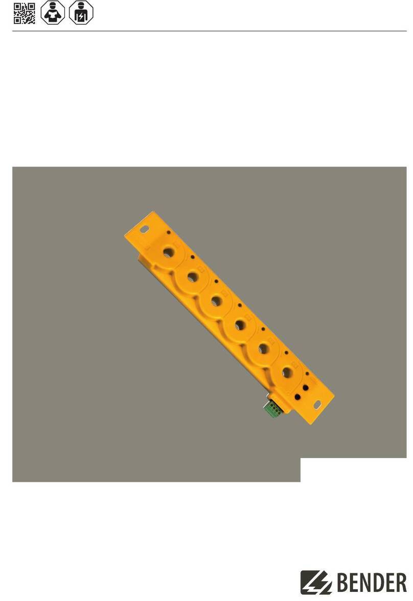
  9. Bender LINETRAXX CTBS25 User manual

Bender LINETRAXX CTBS25 User manual

Scope of delivery
CTBS25, screw adapter, terminal block 1, manual, safety
instructions
Intended use
The AC/DC sensitive CTBS25 (type B) measuring current
transformers convert system leakage and fault currents into
an evaluable measurement signal. The devices are suitable
for detecting fault currents with smooth DC components.
The measuring current transformers can be used in DC, AC,
and 3(N)AC systems. The measurement signal is evaluated
using devices of the RCMS460/490 or EDS440 series, to
which the measuring current transformers are connected.
Installation, connection and commissioning are to be
carried out by electrically skilled persons only! It is es-
sential to follow the existing safety instructions.
Device view
(Dimensions in mm, tolerance ±0.5 mm)
AC/DC sensitive measuring current transformer
Lieferumfang
CTBS25, Schraubadapter, Klemmenblock 1, Handbuch,
Sicherheitshinweise
Bestimmungsgemäße Verwendung
Die allstromsensitiven Messstromwandler CTBS25 (Typ B)
setzen Netzableit- und Fehlerströme in ein auswertbares
Messsignal um. Die Geräte sind geeignet, Fehlerströme
mit glatten Gleichanteilen zu detektieren. Die Mess-
stromwandler können in DC, AC und 3(N)AC-Systemen
eingesetzt werden. Die Auswertung des Messsignals er-
folgt mit Geräten der Serien RCMS460/490 bzw. EDS440,
mit denen die Messstromwandler verbunden werden.
Montage, Anschluss und Inbetriebnahme nur durch
Elektrofachkraft! Beachten Sie unbedingt die bestehen-
den Sicherheitsvorschriften.
Geräteansicht
(Angaben in mm, Toleranz ±0,5 mm)
Degauss and
Auto Zero
65,5 25
26
100,4
Bender
2
1
4
3
LINETRAXX® CTBS25
Allstromsensitiver Messstromwandler
Schraubmontage /
Screw mounting
Element Bemerkung Nr. Element Description
Wandlerkern
entriegeln
Beide Elemente gleichzeitig zusammenpressen
und den CTBS25 aufklappen . 1Unlock current transformer
core
Press both elements together at the same time and
ip the CTBS25 open.
Taster Entmagnetisierung und Osetmessung (mit
spitzem Gegenstand betätigen) 2Push button Degaussing and oset measurement (use pointed
object to press)
CTBS25
1.
2.
4.
„Klick“
3.
3LED
Gerät ist betriebsbereit (leuchtet grün). ADevice is ready for operation (lights green).
Entmagnetisierung/Osetmessung aktiv
(blinkt schnell rot). BDegaussing/oset measurement active (ashes
red quickly).
Kompensationsvermögen der Messtechnik
wurde überschritten (> 100A) (blinkt lang-
sam rot). Entmagnetisierung/Osetmessung
muss durchgeführt werden.
C
Compensation range of the measurement tech-
nology has been exceeded (> 100 A) (ashes red
slowly). Degaussing/oset measurement must
be carried out.
A
B
C
4Klemmenblock 1 / Terminal block 1
Hinweis
Note
Klemme
Terminal Pin Klemme
Terminal
Hinweis
Note
– – 5 6 – –
– – 4 7 S2 (l) RCMS...
EDS440
– – 3 8 S1 (k)
US
GND 2 9 GND
US
+24V 1 10 +24V
Hutschiene /
DIN rail mounting
Montage / Mounting
Handbuch/Manual
CTBS25_D00388_01_M_DEEN/01.2020 DE/EN
CTBS25_D00388_01_M_DEEN/01.2020
Connection
I DeviceDamage due to interference pulses!
The connecting cable (supply, analogue inter-
face…) must not be routed directly past the current
transformer core/primary conductor!
Wiring diagram
Offset calibration
The CTBS25 should be calibrated after installation in the
system to be monitored or in the final installation direc-
tion near the installation location to minimise the effects
of the earth's magnetic field. The device can be calibrated
by pressing the "AUTO ZERO/DEGAUSS" push button.
i
Make sure that no current flows through the meas-
uring current transformer during offset calibration.
If a CTBS25 is installed, the system must be
switched off!
Step Action LED
1Install the measuring current trans-
former in the system and close o
2Supply the device with supply
voltage Us
lights green
permanently
3Start calibration: Press and hold
button for approx. 1 s starts to ash red
quickly
4 Calibration in progress (approx. 10 s) ashes red quickly
5Calibration nished, normal operat-
ing status lights green
permanently
Anschluss
I Geräteschaden durch Störimpulse!
Die Anschlussleitung (Versorgung, analoge
Schnittstelle…) darf nicht direkt am Wandlerkern/
Primärleiter vorbeigeführt werden!
Anschlussbild
F 6 A
L1
L2
L3
N
DC 24 V
AC
DC
GND
24 V
L
N
3
CTBS25
EDS440
RCMS460/490
S1 S2
k l
Offset-Abgleich
Der CTBS25 sollte nach der Installation in der zu überwa-
chenden Anlage oder in der finalen Installationsrichtung
nahe des Einbauorts abgeglichen werden, um Einflüsse
durch das Erdmagnetfeld zu minimieren. Der Abgleich ist
per Tastendruck („AUTO ZERO/DEGAUSS“) möglich.
i
Beachten Sie, dass während des Offset-Abgleichs
kein Strom durch den Messstromwandler fließt. Bei
einem eingebauten CTBS25 muss die Anlage abge-
schaltet sein!
Schritt Aktion LED
1Messstromwandler in der An-
lage montieren und schließen aus
2Gerät mit derVersorgungs-
spannung Usversorgen leuchtet dauerhaft grün
3Abgleich starten: Taste für ca.
1 s gedrückt halten beginnt, schnell rot zu
blinken
4 Abgleich läuft (ca. 10 s) blinkt schnell rot
5Abgleich beendet, normaler
Betriebszustand leuchtet dauerhaft grün
i
Bei Verwendung des CTBS25 als
Differenzstromsensor für Auswertegeräte
nach IEC62020 sind folgende notwendige
Einstellungen am Auswertegerät vorzuneh-
men:
Fehlerspeicher = aus
Ansprechwert IΔn ≥ 30 mA
Messstromwandler = Typ AB
i
When using the CTBS25 as a residual current
sensor for evaluation devices according to
IEC62020, the following necessary settings
must be made on the evaluation device:
Fault memory = off
Response value IΔn ≥ 30 mA
Measuring current transformer = type AB
2 CTBS25_D00388_01_M_DEEN/01.2020
LINETRAXX® CTBS25
Technical data
Values only apply to closed measuring current transformers.
Insulation coordination acc. to IEC 60664-1/IEC 60664-3
Definitions
Measuring circuit (IC1) ........................................................................
............... primary conductors routed through the current transformer
Secondary (IC2) ...........................terminal block 1 (24 V, GND, S1, S2)
Rated voltage ............................................................................ 300 V
Rated voltage (insulated cables)............................................... 600 V
Overvoltage category....................................................................... III
Area of application ................................................... ≤ 2000 m AMSL
Rated impulse voltage IC1/IC2 .........................................................4 kV
Rated insulation voltage IC1/IC2 ................................................... 300 V
Pollution degree ............................................................................... 2
Basic insulation between IC1/IC2 ............................................. 300 V
Supply voltage
Supply voltage US.................................................................... DC 24 V
Operating range of US.................................................................±5 %
Ripple US................................................................................... ≤ 2 %
Inrush current................................................................10 A for 25 µs
Power consumption .............................. ≤ 0.25 W typ. (2.5 W max.)
Measuring circuit
Measuring current transformer, internal diameter .................25 mm
Characteristics according to IEC 62020 and IEC/TR 60755
........................................................................AC/DC sensitive, type B
Frequency bandwidth..................................................DC … 100 kHz
Measuring range IΔn
DC/AC (< 100 kHz).........................................................10… 500 mA
Technische Daten
Werte gelten nur für geschlossenen Messstromwandler.
Isolationskoordination nach IEC 60664-1/IEC 60664-3
Definitionen
Messkreis (IC1) ................... Durch den Wandler geführte Primärleiter
Sekundär (IC2) ...........................Klemmenblock 1 (24 V, GND, S1, S2)
Bemessungsspannung .............................................................. 300 V
Bemessungsspannung (isolierte Kabel)..................................... 600 V
Überspannungskategorie ................................................................ III
Einsatzhöhe ..........................................................≤ 2000 m über NN
Bemessungs-Stoßspannung IC1/IC2 ...............................................4 kV
Bemessungs-Isolationsspannung IC1/IC2 .....................................300 V
Verschmutzungsgrad ....................................................................... 2
Basisisolierung zwischen IC1/IC2 ............................................. 300 V
Versorgungsspannung
Versorgungsspannung US........................................................ DC 24 V
Arbeitsbereich von US.................................................................±5 %
Ripple US.................................................................................... ≤ 2 %
Einschaltstrom...............................................................10 A für 25 µs
Eigenverbrauch ..................................... ≤ 0,25 W typ. (2,5 W max.)
Messkreis
Messstromwandler Innendurchmesser ...................................25 mm
Charakteristik nach IEC 62020 und IEC/TR 60755
.........................................................................allstromsensitiv, Typ B
Frequenzbandbreite.....................................................DC … 100 kHz
Messbereich IΔn
DC/AC (< 100 kHz).........................................................10… 500 mA
Einbau Messstromwandler Installing measuring current transformer
Alle stromführenden Leitungen/Leiter müssen
durch den Messstromwandler geführt werden.
Keine abgeschirmten Leitungen durch den
Messstromwandler führen!
All current-carrying cables must be routed to-
gether through the measuring current transform-
er. Do not route any shielded cables through the
measuring current transformer!
Ein vorhandener Schutzleiter darf grundsätzlich
nicht durch denWandler geführt werden.
PE
L1
L2
L3
N
Never route an existing protective conductor
through the measuring current transformer.
Eine Biegung der Primärleiter darf erst ab dem
angegebenen Mindestabstand erfolgen. Dabei sind
die von den Herstellern vorgeschriebenen
Mindestbiegeradien der verwendeten Leiter
einzuhalten.
* Abstand zum 90°-Winkel = 2 x Außendurchmesser
*
*
The primary conductors may only be bent from the
specified minimum distance. The minimum
bending radius specified by the manufacturers
must be observed.
* Distance to 90° angle = 2 x external diameter
Die Leitungen/Leiter sind in der Mitte des
Messstromwandlers zu zentrieren. Der
Kabeldurchmesser darf maximal die Hälfte des
Wandlerdurchmessers betragen.
The cables must be aligned with the centre of the
measuring current transformer. The cable diame-
ter may not exceed half the current transformer
diameter.
LINETRAXX® CTBS25
CTBS25_D00388_01_M_DEEN/01.2020 3
Rated current In.......................................................................... 100 A
Operating uncertainty...................................................±1 % ±1 mA
Indication
Multicolour LED .................................................................. red, green
Environment/EMC
EMC .....................................................................................IEC 62020
Operating temperature................................................... –25…75 °C
Classification of climatic conditions acc. to IEC 60721
(except condensation and formation of ice)
Stationary use (IEC 60721-3-3) ..................................................... 3K5
Transport (IEC 60721-3-2)............................................................ 2K11
Long-term storage (IEC 60721-3-1) ............................................ 1K22
Classification of mechanical conditions acc. to IEC 60721
Stationary use (IEC 60721-3-3)..................................................... 3M4
Transport (IEC 60721-3-2)............................................................. 2M4
Long-term storage (IEC 60721-3-1) ........................................... 1M12
Terminal block 1, reverse polarity protection
Required terminals are included in the scope of delivery. The connection
conditions of the manufacturer apply.
Manufacturer ............................................................Phoenix Contact
Type ............................PCB plug-in connector - DFMC 0.5/ 5-ST-2.54
Connection properties.........................................................................
rigid .................................................. 0.14…0.5 mm² (AWG 26…20)
flexible ............................................. 0.14…0.5 mm² (AWG 26…20)
with ferrules ....................................0.25…0.34 mm² (AWG 24…22)
Other
Operating mode ................................................continuous operation
Mounting ....................................................................... any position
Degree of protection (DIN EN 60529)........................................... IP30
Flammability class ...............................................................UL94 V-0
Weight....................................................................................≤ 165 g
Ordering details
Bemessungsstrom In.................................................................. 100 A
Betriebsmessabweichung............................................±1 % ± 1 mA
Anzeigen
Mehrfarb-LED ....................................................................... rot, grün
Umwelt/EMV
EMV .....................................................................................IEC 62020
Arbeitstemperatur ......................................................... –25…75 °C
Klimaklassen nach IEC 60721
(ohne Betauung und Eisbildung)
Ortsfester Einsatz (IEC 60721-3-3) ................................................ 3K5
Transport (IEC 60721-3-2) ........................................................... 2K11
Langzeitlagerung (IEC 60721-3-1) .............................................. 1K22
Mechanische Beanspruchung nach IEC 60721
Ortsfester Einsatz (IEC 60721-3-3) ............................................... 3M4
Transport (IEC 60721-3-2) ............................................................ 2M4
Langzeitlagerung (IEC 60721-3-1) ............................................. 1M12
Klemmenblock 1, verpolungssicher
Erforderliche Klemmen sind im Lieferumfang enthalten. Es gelten die
Anschlussbedingungen des Herstellers.
Hersteller ..................................................................Phoenix Contact
Typ ......................Leiterplattensteckverbinder - DFMC 0,5/ 5-ST-2,54
Anschlussvermögen............................................................................
starr .................................................. 0,14…0,5 mm² (AWG 26…20)
flexibel ............................................. 0,14…0,5 mm² (AWG 26…20)
mit Aderendhülse ...........................0,25…0,34 mm² (AWG 24…22)
Sonstiges
Betriebsart .....................................................................Dauerbetrieb
Einbaulage .............................................................................beliebig
Schutzart (DIN EN 60529) ............................................................ IP30
Entflammbarkeitsklasse .......................................................UL94 V-0
Gewicht ..................................................................................≤ 165 g
Bestellangaben
Typ / Type Versorgungsspannung US/ Supply voltage USArt.-Nr / Art.-No.
CTBS25 DC 24 V B98120060
LINETRAXX® CTBS25
Alle Rechte vorbehalten.
Nachdruck und Vervielfältigung
nur mit Genehmigung des Herausgebers.
Bender GmbH & Co. KG
Postfach 1161 • 35301 Grünberg • Deutschland
Londorfer Str. 65 • 35305 Grünberg • Deutschland
Tel.: +49 6401 807-0 • Fax: +49 6401 807-259
E-Mail: [email protected] • www.bender.de
All rights reserved.
Reprinting and duplicating
only with permission of the publisher.
Bender GmbH & Co. KG
PO Box 1161 • 35301 Gruenberg • Germany
Londorfer Str. 65 • 35305 Gruenberg • Germany
Tel.: +49 6401 807-0 • Fax: +49 6401 807-259
E-Mail: [email protected] • www.bender.de

Other Bender Measuring Instrument manuals

Bender RCMB423EM User manual

Bender

Bender RCMB423EM User manual

Bender LINETRAXX RCM420 User manual

Bender

Bender LINETRAXX RCM420 User manual

Bender ISOMETER isoMIL425 User manual

Bender

Bender ISOMETER isoMIL425 User manual

Bender ISOMETER isoBAT425 User manual

Bender

Bender ISOMETER isoBAT425 User manual

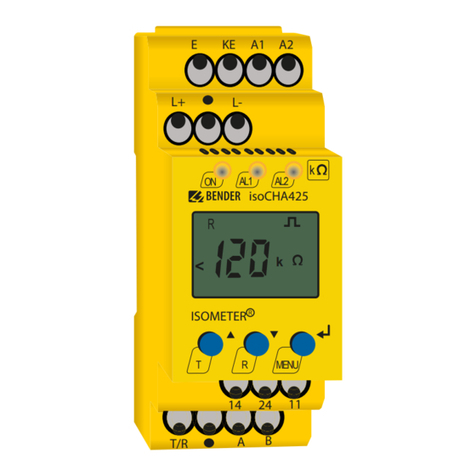
Bender ISOMETER isoPV425 with AGH420 User manual

Bender

Bender ISOMETER isoPV425 with AGH420 User manual

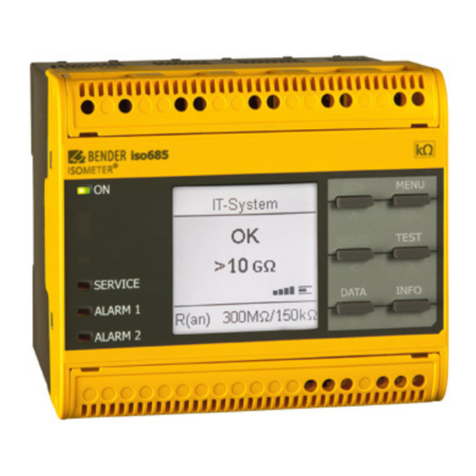
Bender iso685 User manual

Bender

Bender iso685 User manual

Bender ISOMETER isoPV with AGH-PV User manual

Bender

Bender ISOMETER isoPV with AGH-PV User manual

Bender PEM735 User manual

Bender

Bender PEM735 User manual

Bender ISOMETER IR420-D6 User manual

Bender

Bender ISOMETER IR420-D6 User manual

Bender PEM353 User manual
Bender

Bender PEM353 User manual

Bender ISOMETER isoRW425 User manual

Bender

Bender ISOMETER isoRW425 User manual

Bender ISOMETER iso165C User manual

Bender

Bender ISOMETER iso165C User manual

Bender MRCDB423 Series User manual

Bender

Bender MRCDB423 Series User manual

Bender COMTRAXX COM465ID User manual

Bender

Bender COMTRAXX COM465ID User manual

Bender ISOMETER isoES425 User manual

Bender

Bender ISOMETER isoES425 User manual

Bender EDS3090 User manual

Bender

Bender EDS3090 User manual

Bender RCMB330 User manual

Bender

Bender RCMB330 User manual

Bender VME420 User manual

Bender

Bender VME420 User manual

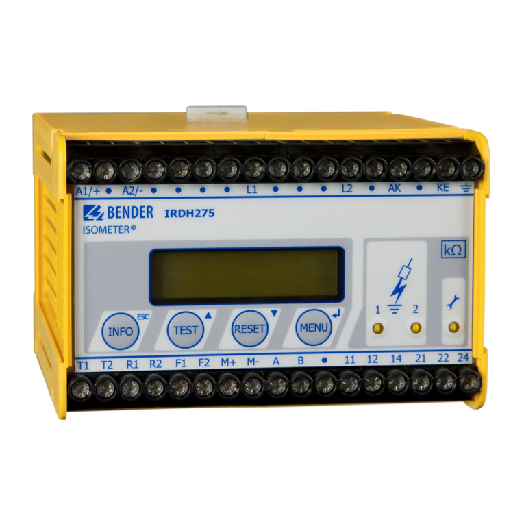
Bender ISOMETER IRDH275 User manual

Bender

Bender ISOMETER IRDH275 User manual

Bender ATICS-2-63A-ISO User manual

Bender

Bender ATICS-2-63A-ISO User manual

Bender RC48N User manual

Bender

Bender RC48N User manual

Bender ISOMETER isoHR685W Series User manual

Bender

Bender ISOMETER isoHR685W Series User manual

Bender ISOMETER IR423-D4 User manual

Bender

Bender ISOMETER IR423-D4 User manual

Bender LINETRAXX RCM410R-24/-2 User manual

Bender

Bender LINETRAXX RCM410R-24/-2 User manual

Popular Measuring Instrument manuals by other brands

ProMeister PT5354 user guide

ProMeister

ProMeister PT5354 user guide

Badger Meter RF-OMS Installation & operation manual

Badger Meter

Badger Meter RF-OMS Installation & operation manual

Emerson FloBoss 107 instruction manual

Emerson

Emerson FloBoss 107 instruction manual

Endress+Hauser airtrol CPC 200 operating instructions

Endress+Hauser

Endress+Hauser airtrol CPC 200 operating instructions

Phabrix Rx 2000 Operation manual

Phabrix

Phabrix Rx 2000 Operation manual

PCB Piezotronics W138A10/038CY020AC Installation and operating manual

PCB Piezotronics

PCB Piezotronics W138A10/038CY020AC Installation and operating manual

Contrel EMA11 user manual

Contrel

Contrel EMA11 user manual

LaMotte WaterLink SpinTouchFF instruction manual

LaMotte

LaMotte WaterLink SpinTouchFF instruction manual

REED R8085 instruction manual

REED

REED R8085 instruction manual

Ankom TDF28 Service Procedure

Ankom

Ankom TDF28 Service Procedure

Amprobe SM70 Operaing instructions

Amprobe

Amprobe SM70 Operaing instructions

Danfoss SonoMeter 30 installation guide

Danfoss

Danfoss SonoMeter 30 installation guide

PCB Piezotronics IMI SENSORS 607A01 Installation and operating manual

PCB Piezotronics

PCB Piezotronics IMI SENSORS 607A01 Installation and operating manual

Emerson Rosemount Analytical X-STREAM X2 Series instruction manual

Emerson

Emerson Rosemount Analytical X-STREAM X2 Series instruction manual

Curbell CareSense CSM-PM100 Quick setup guide

Curbell

Curbell CareSense CSM-PM100 Quick setup guide

PCB Piezotronics 333D Installation and operating manual

PCB Piezotronics

PCB Piezotronics 333D Installation and operating manual

Watts HF scientific 28052 Owner's and user's manual

Watts

Watts HF scientific 28052 Owner's and user's manual

V&A M266 Series user manual

V&A

V&A M266 Series user manual

manuals.online logo
manuals.online logoBrands
  • About & Mission
  • Contact us
  • Privacy Policy
  • Terms and Conditions

Copyright 2025 Manuals.Online. All Rights Reserved.