Bender MLS470 User manual

1
Load switches
Intended use
MLS470, MLS473, and MLS474 load switches are intended for use
in UM107E, UM107ET and UM107ETU switchover equipment. In
this context they are installed as a replacement for the MLS490,
MLS493 and MLS494 devices, which are no longer available.
MLS47x devices are used for two, three or four-pole switching of
the power supply in medical environments.
General safety instructions
Installation, connection and commissioning should only be car-
ried out by an electrical technician.
It is essential that you observe the following:
●The existing safety regulations and
●the attached page entitled “Important safety instructions
for BENDER products”.
Device-specific safety instructions
Description of function
The MLS470 is a motor-operated switch with two stable switch-
ing states. The switching process is controlled by means of the
SUA470 (SUD470) or SUA490 (SUD490) low-voltage relay signals.
This ensures that the motor is only connected to the voltage dur-
ing the switching operation, and is not supplied with current dur-
ing a standstill. As a result, undesirable switching due to short-
term voltage dips (which occur when contactors are used) is pre-
vented.
Front view
Fig. 1: MLS470 for two-pole switching
Never press load switches manually! Doing this can
present the risk of both power linesbeing switched on
at the same time. In such cases, the electrical installa-
tion may sustain damage and the device destroyed
beyond repair.
Ex works, the settings for MLS47x load switches are
already suitable for use in BENDER UM107E... switch-
over equipment. The switchover equipment is only
guaranteed to function safely if these settings remain
unchanged.
Lastschalter
Bestimmungsgemäße Verwendung
Lastschalter MLS470, MLS473, und MLS474 sind zum Einsatz in
Umschalteinrichtungen UM107E, UM107ET und UM107ETU be-
stimmt. Dort werden Sie als Ersatz für die nicht mehr verfügbaren
MLS490, MLS493, und MLS494 eingebaut. MLS47x dienen zum
zwei-, drei- oder vierpoligen Umschalten der Stromversorgung
von medizinisch genutzten Räumen.
Sicherheitshinweise allgemein
Montage, Anschluss und Inbetriebnahme nur durch Elektrofach-
kraft!
Beachten Sie unbedingt:
●die bestehenden Sicherheitsvorschriften und
●das beiliegende Blatt "Wichtige sicherheitstechnische Hin-
weise für BENDER-Produkte".
Sicherheitshinweise gerätespezifisch
Funktionsbeschreibung
MLS470 sind motorbetriebene Schalter mit zwei stabilen Schalt-
zuständen. Die Steuerung der Antriebe erfolgt durch den Befehl
des Unterspannungsrelais SUA470 (SUD470) bzw. SUA490
(SUD490). Dadurch ist gewährleistet, dass der Motor nur während
des Schaltvorganges an Spannung liegt und bei Stillstand keinen
Strom aufnimmt. Unerwünschtes Schalten durch kurzzeitige
Spannungseinbrüche, wie es bei Schützen der Fall ist, wird da-
durch verhindert
Frontansicht
Abb. 1: MLS470 für zweipolige Umschaltung
Lastschalter nie von Hand betätigen! Bei Betätigung
von Hand besteht die Gefahr, dass beide Leistungslei-
tungen gleichzeitig eingeschaltet werden. In diesem
Fall drohen Sachschäden an der elektrischen Anlage
und die Zerstörung des Gerätes.
Lastschalter MLS47x sind ab Werk bereits passend für
den Einsatz in BENDER-Umschalteinrichtungen
UM107E... eingestellt. Nur wenn diese Einstellungen
unverändert bleiben ist die sichere Funktion der Um-
schalteinrichtung gewährleistet.
63A
415V~
13
24
0
-
0ff
0
-
0ff
MLS470 01/2006
MLS470, MLS473, MLS474
BP210006 / 12.2007
Deutsch English

2BP210006 / 12.2007
MLS470, MLS473, MLS474
Installation and connection
Mounting
The device is suitable for snap-on mounting on DIN rails conform-
ing to IEC 60715:1995-10.
Outline drawing
Fig. 2: MLS470, MLS473 and MLS474 dimensions
MLS49x -> MLS47x replacement
Follow the steps below to install the MLS47x in existing UM107E
switchover equipment:
Preparatory steps:
1. Remove cable ties on the cable harness around the
MLS49x.
2. MLS47x devices are 9 mm (0.5 SU) wider than MLS49x (SU
= space unit, to DIN 43880, dimensions 150 x 18 mm). You
can create the space required as follows (only necessary
for UM107E…):
Remove STW2 measuring current transformer from DIN
rails and attach to the side of the rack.
Disconnecting and removing the existing MLS49x:
1. Control cables:
– Label with L, N, L0, LI
– Disconnect from motor connections
– Place in the lower cable harness
– Lengthen cables if necessary
2. Signalling lines 95, 96 und 98:
– Label with 95, 96 und 98
– Disconnect
– Place in the upper cable harness
– Lengthen cables if necessary
Before fitting the device and working on the device con-
nections, make sure that no voltage is present. Failure to
comply with this requirement will expose personnel to
the risk of electric shock. Furthermore, the electrical in-
stallation may sustain damage and the device be de-
stroyed beyond repair.
Montage und Anschluss
Montage
Das Gerät ist für Schnellmontage auf Hutprofilschiene nach IEC
60715:1995-10 geeignet.
Maßbild
Abb. 2: Maße MLS470, MLS473 und MLS474
MLS49x -> MLS47x Austausch
Führen Sie die folgenden Schritte aus um MLS47x in eine beste-
hende Umschalteinrichtung UM107E einzubauen:
Vorbereitende Arbeiten:
1. Kabelbinder am Kabelbaum im Bereich der MLS49x entfer-
nen.
2. MLS47x sind je 9 mm (0,5 PLE) breiter als MLS49x (PLE =
Platzeinheit, nach DIN 43880, Abmessungen 150 x 18 mm).
Den benötigten Platz schaffen Sie wie folgt (nur bei
UM107E... erforderlich):
Messstromwandler STW2 von Hutschiene lösen und auf
der Seite des Baugruppenträgers befestigen.
Bestehende MLS49x abklemmen und ausbauen:
1. Steuerleitungen
– mit L, N, L0, LIkennzeichnen,
– von den Motorantrieben abklemmen
– und in den unteren Kabelbaum verlegen.
– Leitungen, falls erforderlich, verlängern.
2. Meldeleitungen 95, 96 und 98
– mit 95, 96 und 98 kennzeichnen,
– abklemmen,
– und in den oberen Kabelbaum verlegen.
– Leitungen, falls erforderlich, verlängern.
Stellen Sie vor Einbau des Gerätes und vor Arbeiten
an den Anschlüssen des Gerätes sicher, dass die An-
lage spannungsfrei ist. Wird dies nicht beachtet, so
besteht für das Personal die Gefahr eines elektrischen
Schlages. Außerdem drohen Sachschäden an der ele-
ktrischen Anlage und die Zerstörung des Gerätes.
45
90
99
117
135
MLS470
MLS474
MLS473
44
75
6

3
BP210006 / 12.2007
MLS470, MLS473, MLS474
3. Die Meldeleitungen 05 und 06
– mit 05 und 06 kennzeichnen
– und abklemmen.
4. Leistungsleitungen
– mit Leitung 1 und 2 kennzeichnen
– und abklemmen.
5. Die MLS49x ausbauen.
Bei Umschalteinrichtung mit Klappfenster:
MLS47x sind etwas höher als MLS49x. Den benötigten Platz
schaffen Sie wie folgt:
– Hutschiene 35x15 austauschen gegen Hutschiene
35x7,5
– oder den Abstand des Klappfensters von der Abde-
ckung um 2...5 mm erhöhen.
Neue MLS47x einbauen und anschließen:
1. Motorantrieb anschließen:
2. Meldeleitungen anschließen:
3. Leistungsleitungen 1 und 2 anschließen.
Abschließende Arbeiten und Prüfung
1. Alle Anschlüsse anhand des Stromlaufplans noch einmal
überprüfen.
2. Kabelbaum zusammenbinden.
3. Funktion der Umschalteinrichtung UM107E... gemäß den
Vorgaben in der zugehörigen Bedienungsanleitung über-
prüfen.
Technische Daten
Motorantrieb
Bemessungsspannung US.................................................................................................. AC 230 V
Mindestspannung.................................................................................................................... 207 V
Einschaltimpulsdauer...............................................................................................................50 ms
Ausschaltimpulsdauer..............................................................................................................50 ms
Dauer des Einschaltvorgangs ............................................................................................. <500 ms
Dauer des Ausschaltvorgangs ............................................................................................ <200 ms
Elektrische Schaltlebensdauer.................................................................................................10 000
Anschluss flexibler/massiver Leiter, min./max. ......................................... 0,75...2,5 / 1...2,5 mm2
Kennzeichnung an den
Leitungen
Kennzeichnung am MLS47x
LL
NN
LOO
LII
Kennzeichnung an den
Leitungen
Kennzeichnung am MLS47x
05 11
06 12
95 95 (21)
96 96 (22)
98 98 (24)
3. Signalling lines 05 and 06
– Label with 05 and 06
– Disconnect
4. Power lines
– Label as line 1 and 2
– Disconnect
5. Remove the MLS49x
Switchover equipment with swing-up transparent cover:
MLS47x are a slightly higher than MLS49x. You can create the
space required as follows:
– Replace DIN rail 35x15 by DIN rail 35x7.5
– or increase the distance between the swing-up transpa-
rent window and the cover of the switchover module
by 2...5 mm.
Install and connect the new MLS47x:
1. Connect the motor drive:
2. Connect the signalling lines:
3. Connect the power lines 1 and 2.
Final steps and test
1. Check all connections against the circuit diagram once
again.
2. Tie the cable harness together.
3. Check the function of the UM107E... switchover equip-
ment on the basis of the associated operating manual.
Technical data
Motor drive
Rated voltage US................................................................................................................. AC 230 V
Minimum voltage..................................................................................................................... 207 V
On-pulse duration ....................................................................................................................50 ms
Off-pulse duration ....................................................................................................................50 ms
Opening operation...............................................................................................................<500 ms
Closing operation.................................................................................................................<200 ms
Electrical service life, number of cycles...................................................................................10 000
Connection flexible/massive conductors, min./max.................................. 0.75...2.5 / 1...2.5 mm2
Labelling of the conductors Labelling of the MLS47x
LL
NN
LOO
LII
Labelling of the conductors Labelling of the MLS47x
05 11
06 12
95 95 (21)
96 96 (22)
98 98 (24)

4BP210006 / 12.2007
MLS470, MLS473, MLS474
Londorfer Str. 65 •35305 Grünberg Fax: +49 (0)6401-807-259 Web: http://www.bender-de.com
Postfach 1161 •35301 Grünberg
Alle Rechte vorbehalten.
Nachdruck und Vervielfältigung
nur mit Genehmigung des Herausgebers.
Änderungen vorbehalten!
©Dipl.-Ing. W. Bender GmbH & Co.KG
All rights reserved.
Reprinting and duplicating
only with permission of the publisher.
Subject to change!
©Dipl.-Ing. W. Bender GmbH & Co.KG
Hauptschalter
Bemessungsspannung ...................................................................................................... AC 415 V
Bemessungsstrom IN.................................................................................................................. 63 A
Bemessungsschaltvermögen bei 415 V AC, cos ϕ = 0,65................................................3 x Inom
Zulässiger Überlaststrom bis zu 1 Sekunde ................................................................................2 kA
Mechanische Schaltlebensdauer (Ein + Aus) ...................................................................> 20 000
Elektrische Schaltlebensdauer, cos ϕ = 0,95, Un und In....................................................>1500
Kurzschlussfestigkeit mit vorgeordneten Sicherungen.................................................. 16 kA (eff.)
Kurzschlussfestigkeit ohne vorgeordnete Sicherungen ............................................7 kA (Scheitel)
Schutzart .....................................................................................................................................IP20
Anschlussklemmschrauben ...............................................................................................Pozidriv 2
Anschluss, min./max.......................................................................................................6 / 50 mm2
Hilfskontakte (Meldeleitungen)
Nennstrom.....................................................................................................................................5 A
Nennspannung...............................................................................AC 230 V / DC 220 V (bei 0,5 A)
Elektrische Schaltlebensdauer.................................................................................................10 000
Anschluss flexibler/massiver Leiter, min./max. ......................................... 0,75...2,5 / 1...2,5 mm2
Allgemeine Daten
Umgebungstemperatur (Gerät in Betrieb).................. -5 ºC...+40 ºC (bei max. 54 A bis +55 °C)
Umgebungstemperatur (bei Lagerung) ................................................................. -40 ºC...+70 ºC
Einbaulage ............................................................................................................................ beliebig
Schnellbefestigung auf Hutprofilschiene............................................... DIN EN 60715 / IEC 60715
Gewicht ca. ............................................................................................................ MLS470: 675 g
................................................................................................................................. MLS473: 820 g
................................................................................................................................. MLS474: 960 g
Bestellangaben
Typ Beschreibung Art.Nr.
MLS470 Lastschalter, motorgetrieben
für 2-pol. Umschalteinrichtung
Us= AC 230 V, IN=63 A; zweipolig
B 927 184
MLS473 Lastschalter, motorgetrieben
für 3-pol. Umschalteinrichtung
Us= AC 230 V, IN=63 A; dreipolig
B 927 185
MLS474 Lastschalter, motorgetrieben
für 4-pol. Umschalteinrichtung
Us= AC 230 V, IN=63 A; vierpolig
B 927 186
Main switch
Rated insulation voltage .................................................................................................... AC 415 V
Rated current IN...........................................................................................................................63 A
Rated switching capacity at 415 V AC, cos ϕ = 0.65........................................................3 x Inom
Permissible overload current up to 1 sec....................................................................................2 kA
Mechanical service life (On + Off)..................................................................................... > 20 000
Electrical service life, cos ϕ = 0.95, Un and In.................................................................... >1500
Short-circuit strength with upstream fuses ................................................................16 kA (r.m.s.)
Short-circuit strength without upstream fuses.............................................................. 7 kA (peak)
Degree of protection ...................................................................................................................IP20
Screw-clamping terminals.......................................................................................Pozidriv 2 screw
Connection, min./max. ...................................................................................................6 / 50 mm2
Auxiliary contacts (signalling lines)
Nominal current.............................................................................................................................5 A
Nominal voltage...............................................................................AC 230 V / DC 220 V (at 0.5 A)
Electrical service life, number of cycles...................................................................................10 000
Connection flexible/massive conductor, min./max................................... 0.75...2.5 / 1...2.5 mm2
General data
Ambient temperature (device in operation)............ -5 ºC...+40 ºC (at max. 54 A, up to +55 °C)
Storage temperature range..................................................................................... -40 ºC...+70 ºC
Mounting....................................................................................................................... any position
DIN rail mounting acc. to ....................................................................... DIN EN 60715 / IEC 60715
Weight approx. ...................................................................................................... MLS470: 675 g
.................................................................................................................................MLS473: 820 g
.................................................................................................................................MLS474: 960 g
Ordering information
Type Description Art.No.
MLS470 Load switch, motor-operated
for 2-pole switchover equipment
Us= AC 230 V, IN=63 A; two-pole
B 927 184
MLS473 Load switch, motor-operated
for 3-pole switchover equipment
Us= AC 230 V, IN=63 A; three-pole
B 927 185
MLS474 Load switch, motor-operated
for 4-pole switchover equipment
Us= AC 230 V, IN=63 A; four-pole
B 927 186
This manual suits for next models
2
Other Bender Switch manuals
Bender
Bender ATICS DIO Series User manual
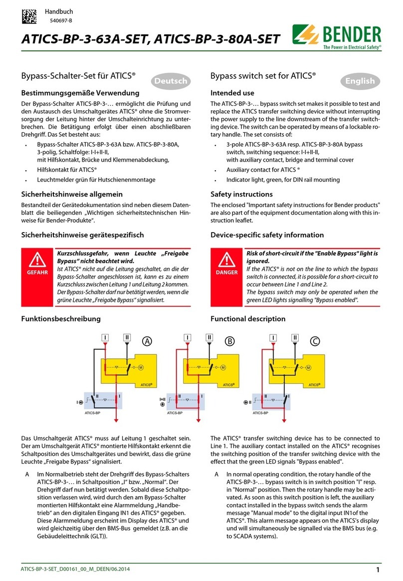
Bender
Bender ATICS-BP-3 Series User manual
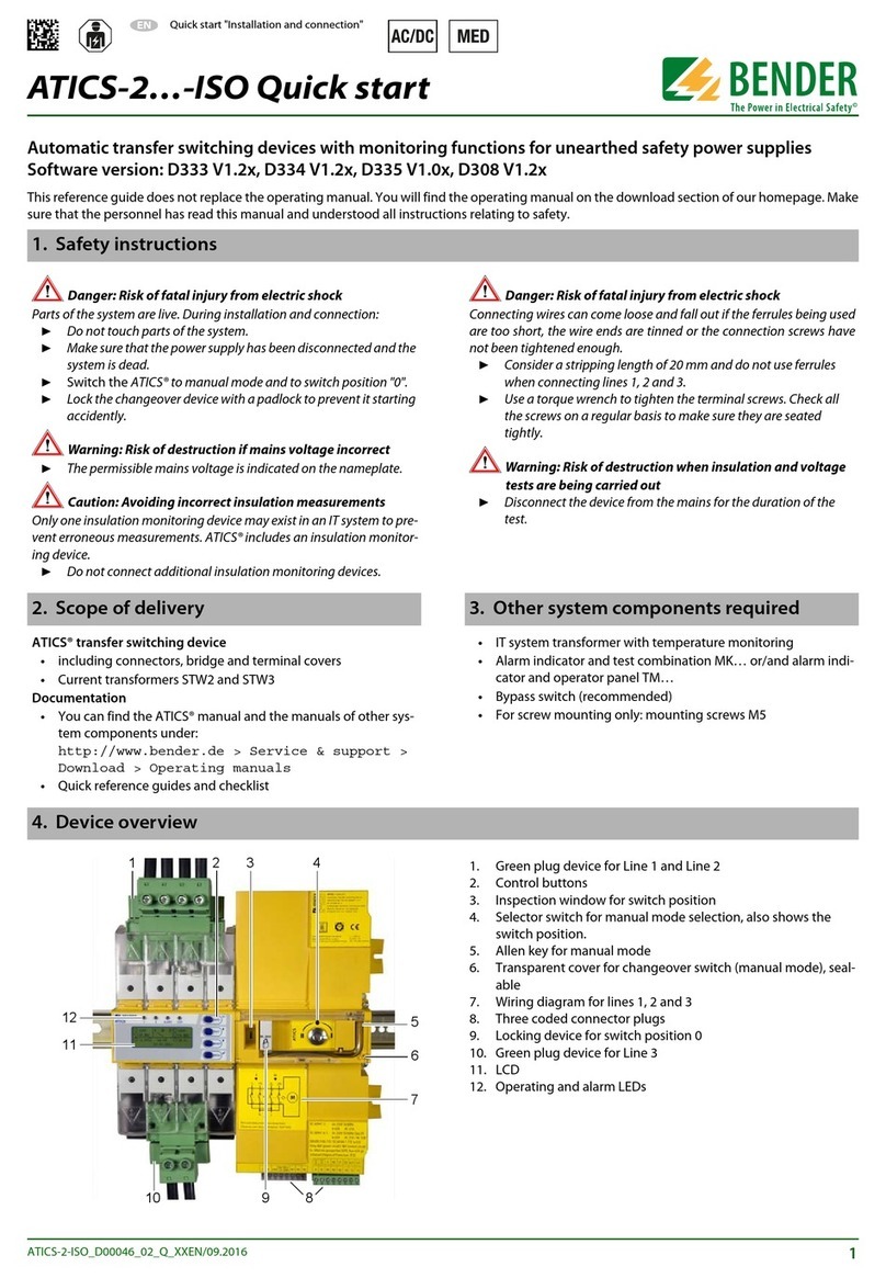
Bender
Bender ATICS-2-ISO Series User manual
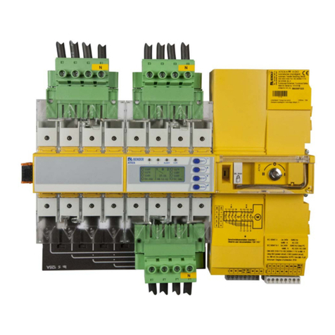
Bender
Bender ATICS-2-63A-DIO User manual
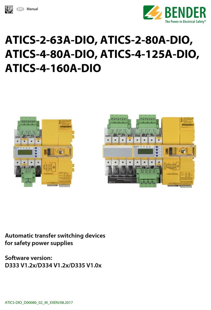
Bender
Bender ATICS-2-63A-DIO User manual

Bender
Bender ATICS-2-63A-ISO User manual
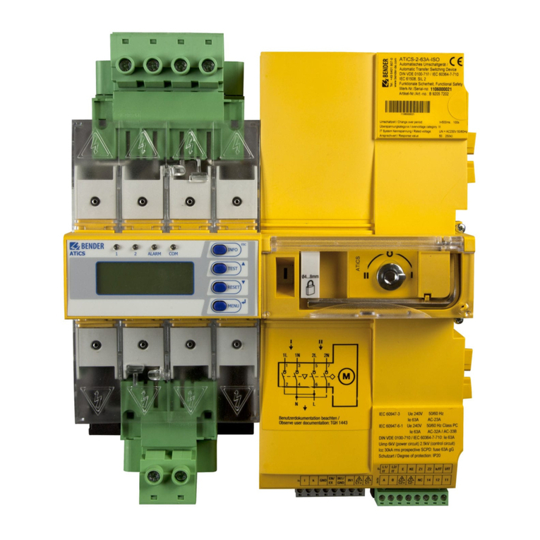
Bender
Bender ATICS DIO Series User manual
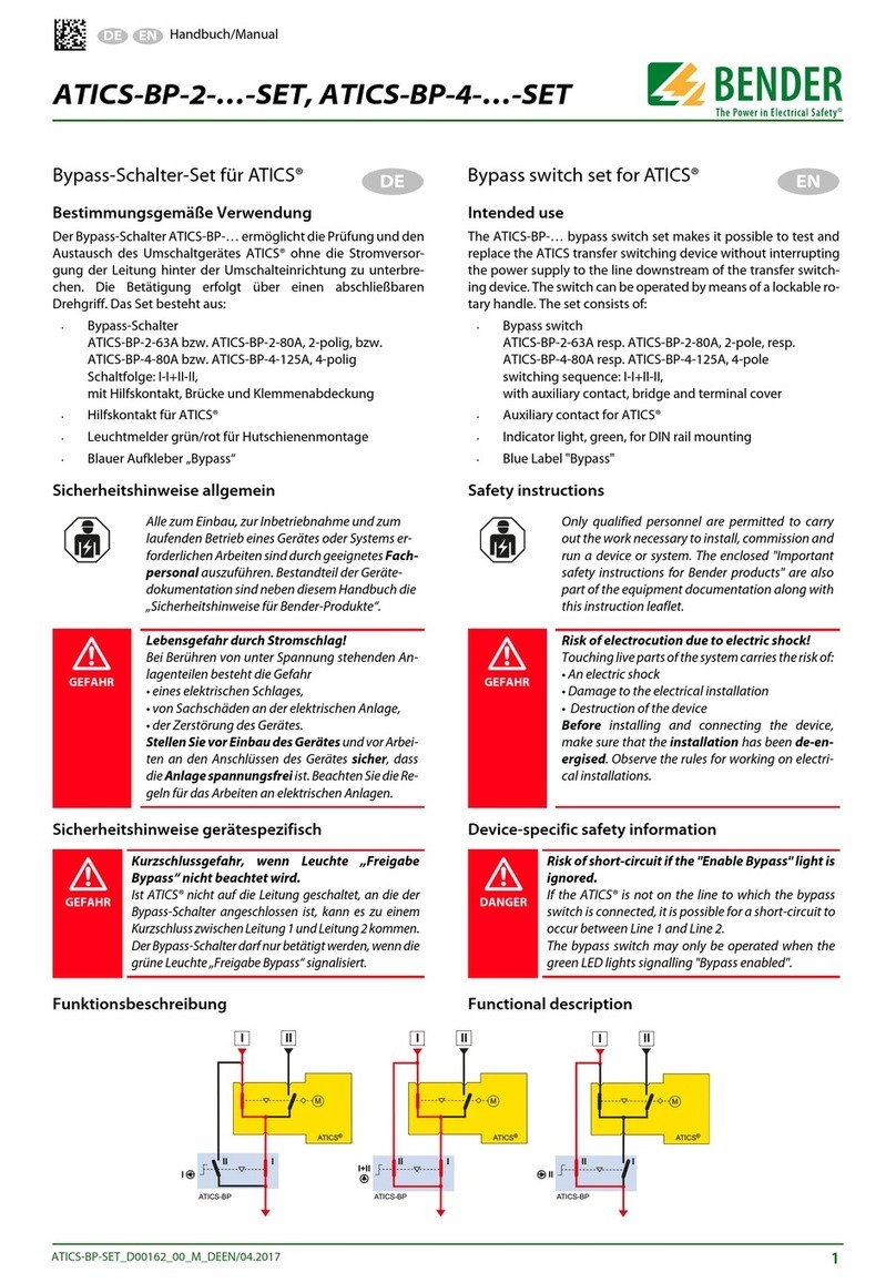
Bender
Bender ATICS-BP-2 SET Series User manual
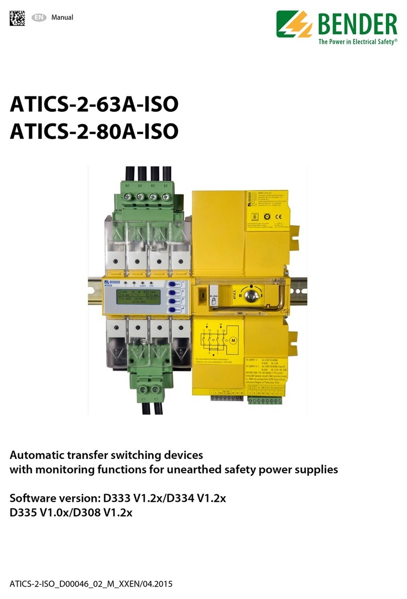
Bender
Bender ATICS-2-63A-ISO User manual
Popular Switch manuals by other brands

ENFORCER
ENFORCER EB-P116-60HQ manual

Gefen
Gefen DVI-422N user manual

ZyXEL Communications
ZyXEL Communications EM-422/EM-412 user guide
LEGRAND
LEGRAND adorne WNAL23 quick start guide
Rose electronics
Rose electronics Xtensys Nstallation and operations manual
Ubiquiti
Ubiquiti UniFi US-48-500W quick start guide
