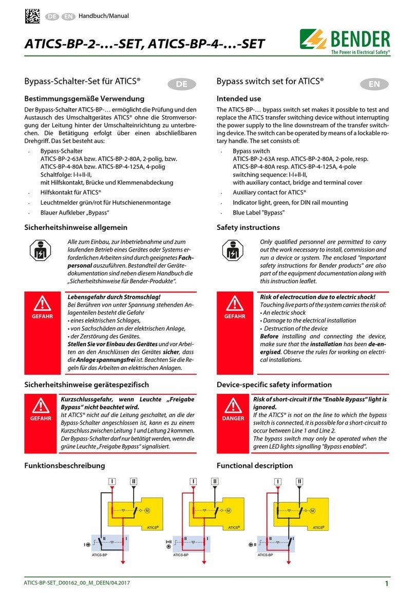
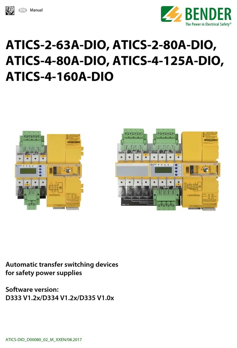
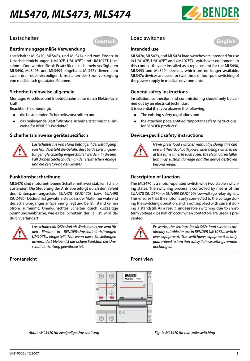
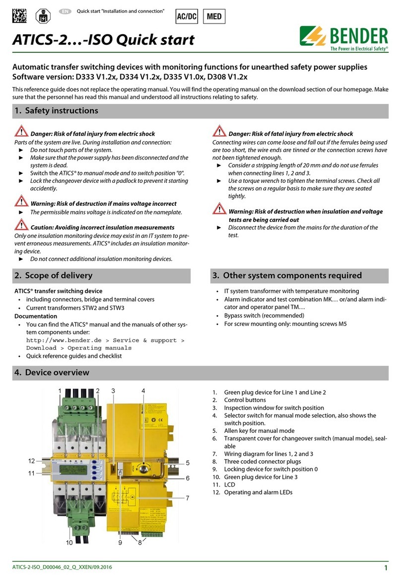
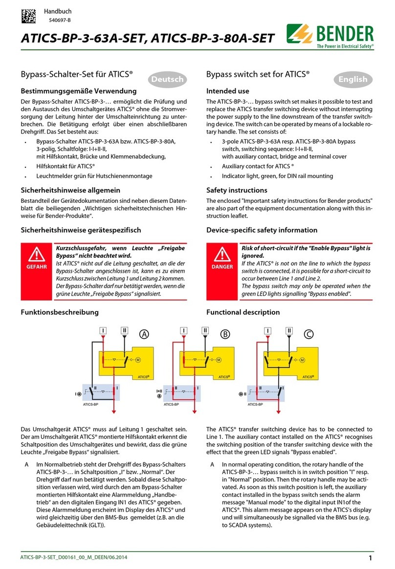
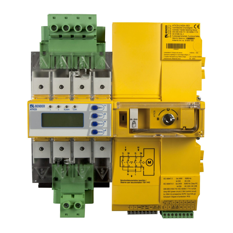
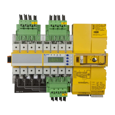
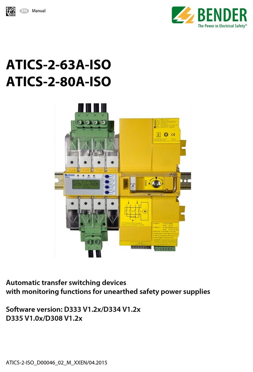
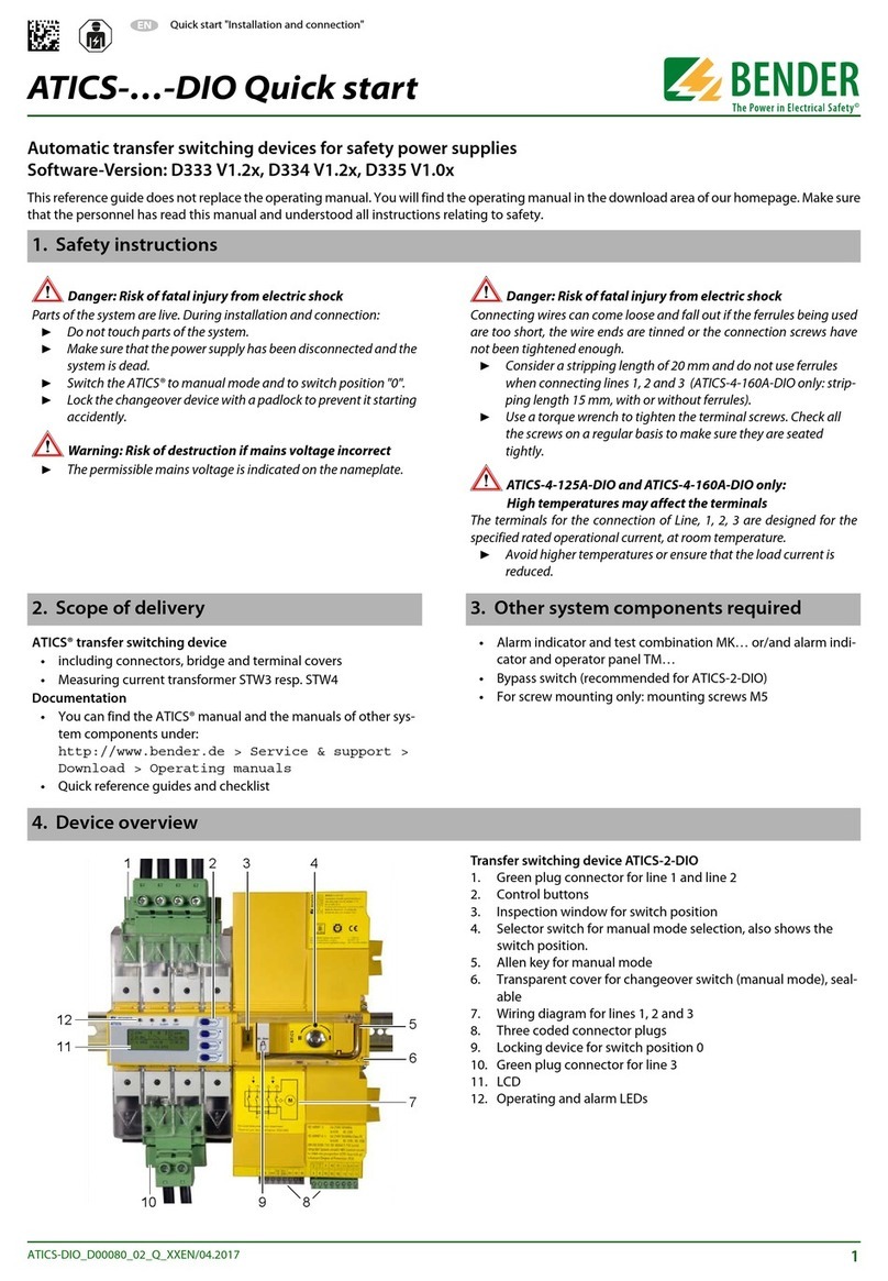
Bender ATICS-2-63A-ISO User manual

Manual
EN
ATICS-2-ISO_D00046_03_M_XXEN/08.2017
ATICS-2-63A-ISO
ATICS-2-80A-ISO
Automatic transfer switching devices
with monitoring functions for unearthed safety power supplies
Software version: D333 V1.2x/D334 V1.2x
D335 V1.0x/D308 V1.2x

Bender GmbH & Co. KG
P.O. Box 1161 • 35301 Gruenberg • Germany
Londorfer Straße 65 • 35305 Gruenberg • Germany
Tel.: +49 6401 807-0 • Fax: +49 6401 807-259
© Bender GmbH & Co. KG
All rights reserved.
Reprinting only with permission
of the publisher.
Subject to change!
Photos: Bender archives.

3
Table of Contents
ATICS-2-ISO_D00046_03_M_XXEN/08.2017
1. Important information ........................................................................................... 7
1.1 How to use this manual ......................................................................................................... 7
1.2 Technical support: service and support ........................................................................... 8
1.2.1 First level support .................................................................................................................... 8
1.2.2 Repair service ............................................................................................................................ 8
1.2.3 Field service ................................................................................................................................ 8
1.3 Training courses ....................................................................................................................... 9
1.4 Delivery conditions ................................................................................................................. 9
1.5 Inspection, transport and storage ..................................................................................... 9
1.6 Warranty and liability ............................................................................................................. 9
1.7 Disposal .................................................................................................................................... 10
2. Safety instructions ............................................................................................... 11
2.1 General safety instructions ................................................................................................ 11
2.2 Work activities on electrical installations ..................................................................... 11
2.3 Intended use ........................................................................................................................... 11
2.4 Device-specific safety instructions ................................................................................. 12
2.5 General safety instructions ................................................................................................ 12
3. System description .............................................................................................. 13
3.1 Properties ................................................................................................................................. 13
3.1.1 Product description .............................................................................................................. 13
3.1.2 Changeover ............................................................................................................................. 13
3.1.3 IT system (unearthed power supply) ............................................................................. 13
3.1.4 Messages .................................................................................................................................. 13
3.1.5 Other functions ...................................................................................................................... 13
3.2 Functional safety ................................................................................................................... 14
3.2.1 Product life-cycle management ...................................................................................... 14
3.3 Application examples .......................................................................................................... 15
3.3.1 Application example operating theatre ....................................................................... 15
3.3.2 Example intensive care unit .............................................................................................. 16
3.4 ATICS® tasks ............................................................................................................................. 17
3.5 The ATICS® functions ........................................................................................................... 17
3.5.1 The automatic transfer switching device ..................................................................... 17

Table of Contents
4ATICS-2-ISO_D00046_03_M_XXEN/08.2017
3.5.1.1 Time diagram: Changeover between the preferred and the redundant line .
19
3.5.1.2 Time diagram: Staggered switching after complete power failure .............. 20
3.5.1.3 Time diagram: Changeover to generator mode .................................................. 21
3.5.2 IT system monitoring ........................................................................................................... 22
3.5.3 Monitoring the device functions ..................................................................................... 22
3.5.4 Power supply ........................................................................................................................... 23
3.5.5 Manual mode .......................................................................................................................... 23
3.6 The ATICS-2-ISO front view ............................................................................................... 24
4. Installation and connection ............................................................................... 25
4.1 Mounting .................................................................................................................................. 25
4.1.1 Dimension diagram .............................................................................................................. 25
4.1.2 Removing the terminal covers .......................................................................................... 26
4.1.3 Mounting on DIN rail ............................................................................................................ 26
4.1.4 Screw mounting on plate ................................................................................................... 27
4.2 Connection ............................................................................................................................... 28
4.2.1 Short-circuit protection ....................................................................................................... 28
4.2.2 Connecting ATICS® safely ...................................................................................................30
4.2.3 Connection example: ATICS® basic configuration ..................................................... 32
4.2.4 Connection example: ATICS® with bypass switch ..................................................... 33
4.2.5 Connection example: ATICS® with bypass switch and EDS151 ............................ 34
4.2.6 Connection example: ATICS® for 400-volt systems ................................................... 35
4.2.7 Instructions for connection ................................................................................................36
4.2.7.1 Transformers for the IT system .................................................................................. 36
4.2.7.2 Temperature sensors ..................................................................................................... 36
4.2.7.3 BMS bus .............................................................................................................................. 36
4.2.7.4 MK… alarm indicator and test combination and TM… alarm indicator and
operator panels ............................................................................................................... 36
4.2.7.5 SCADA systems (Supervisory Control and Data Acquisition) ......................... 36
4.2.7.6 Insulation fault locator EDS151 (optional) ............................................................. 36
4.2.7.7 Bypass switch (optional) ............................................................................................... 36
4.2.8 Fastening, inserting and securing connections .......................................................... 37
4.3 Other functions ...................................................................................................................... 38
4.3.1 Sealing the transparent cover of the transfer switching device ........................... 38
4.3.2 Manual mode .......................................................................................................................... 38
4.3.3 Locking the transfer switching device with a padlock ............................................. 39
5. Commissioning, settings and testing ............................................................... 41
5.1 Design and installation ........................................................................................................ 41

Table of Contents
5
ATICS-2-ISO_D00046_03_M_XXEN/08.2017
5.1.1 Configure MK… or TM… ................................................................................................... 42
5.1.2 ATICS® messages on the BMS bus (channel use) ....................................................... 42
5.1.3 Tests, decommissioning .....................................................................................................43
5.2 Setting and testing according to the checklist .......................................................... 44
5.3 Addressing examples ..........................................................................................................45
6. Operation ............................................................................................................... 47
6.1 Operating and display elements ..................................................................................... 47
6.2 Quick reference guide ......................................................................................................... 48
6.2.1 Display under normal operating conditions ............................................................... 48
6.2.2 Display during fault condition ......................................................................................... 49
6.2.3 Test function ........................................................................................................................... 50
6.2.3.1 Test menu 1: IT system ................................................................................................. 51
6.2.3.2 Test menu 2: Autom. changeover ............................................................................ 52
6.2.3.3 Test menu 3: Manual changeover ............................................................................ 52
6.2.3.4 Test menu 4: Last switch .............................................................................................. 53
6.2.3.5 Test menu 5: Generator ............................................................................................... 54
6.2.3.6 Test menu 6: Test communication .......................................................................... 54
6.2.4 Reset function ........................................................................................................................ 55
6.2.4.1 Reset menu 1: Alarm ..................................................................................................... 56
6.2.4.2 Reset menu 2: SwitchBackLock ................................................................................. 56
6.2.4.3 Reset menu 3: Changeover ......................................................................................... 57
7. Menu mode: Operation and setting ................................................................. 59
7.1 Switching on and calling up the main menu .............................................................. 59
7.2 Menu overview diagram .................................................................................................... 60
7.3 Main menu functions ........................................................................................................... 61
7.3.1 Menu 1: Alarm/meas.values .............................................................................................. 62
7.3.2 Menu 2: Changeover ............................................................................................................ 62
7.3.3 Menu 3: History/Logger ...................................................................................................... 63
7.3.3.1 Operating example: History ....................................................................................... 64
7.3.3.2 Operating example: Config.logger .......................................................................... 64
7.3.4 Menu 4: Settings .................................................................................................................... 65
7.3.4.1 Settings menu 1: Changeover ................................................................................... 66
7.3.4.2 Settings menu 2: Voltage ............................................................................................ 68
7.3.4.3 Settings menu 3: Current ............................................................................................ 69
7.3.4.4 Settings menu 4: IT system ......................................................................................... 70
7.3.4.5 Settings menu 5: Relay ................................................................................................. 71
7.3.4.6 Settings menu 6: Digital input ................................................................................... 72
7.3.4.7 Settings menu 7: Data logger .................................................................................... 74

Table of Contents
6ATICS-2-ISO_D00046_03_M_XXEN/08.2017
7.3.4.8 Settings menu 8: Language ........................................................................................ 75
7.3.4.9 Settings menu 9: Interface ........................................................................................... 75
7.3.4.10 Settings menu 10: Clock ............................................................................................... 76
7.3.4.11 Settings menu 11: Password ....................................................................................... 77
7.3.4.12 Settings menu 12: Service ........................................................................................... 78
7.3.5 Menu 5: Control ...................................................................................................................... 79
7.3.6 Menu 6: Digital input ............................................................................................................ 79
7.3.7 Menu 7: Info ............................................................................................................................. 79
8. Troubleshooting ................................................................................................... 81
8.1 Fault and alarm messages .................................................................................................. 81
8.1.1 Plain text messages ............................................................................................................... 81
8.1.2 Messages with error code or service code ................................................................... 82
8.2 Frequently asked questions ............................................................................................... 84
9. Periodic verification and service ....................................................................... 87
9.1 Periodic verification .............................................................................................................. 87
9.2 Maintenance ............................................................................................................................ 88
9.3 Cleaning .................................................................................................................................... 88
9.4 Operation with bypass switch .......................................................................................... 88
9.5 Replace ATICS® ....................................................................................................................... 89
9.5.1 Removing the existing ATICS® .......................................................................................... 90
9.5.2 Installing a new ATICS® ........................................................................................................ 93
10. Technical data ..................................................................................................... 95
10.1 Tabular data ............................................................................................................................. 95
10.2 TÜV test report according to VDE0100 Part 710 ........................................................ 99
10.3 TÜV certificate regarding functional safety .............................................................. 100
10.4 Standards and certifications ........................................................................................... 101
10.5 Ordering details ................................................................................................................... 102
10.6 Additional documents ...................................................................................................... 103
INDEX ......................................................................................................................... 105

7
ATICS-2-ISO_D00046_03_M_XXEN/08.2017
1. Important information
1.1 How to use this manual
This manual describes how to operate the ATICS® automatic transfer switching device.
Before using the devices, please read this operating manual, the supplement entitled "Important
safety instructions for Bender products" and the instruction leaflets supplied with the individual sys-
tem components.
In this manual, the two redundant supply lines of the power supply are labelled as follows:
– "Preferred supply" or "Preferred line" and
– "Second supply" or "Redundant line".
Devices with displays use the terms "Line 1" and "Line 2" in the text they indicate.
Always keep this manual within easy reach for future reference.
To make it easier for you to understand and revisit certain sections in this manual, we have used sym-
bols to identify important instructions and information. The meaning of these symbols is explained
below:
This manual is intended for qualified personnel working in electrical engineer-
ing and electronics, and in particular for those designing, installing and operat-
ing electrical equipment in the medical and non-medical sector.
This signal word indicates that there is a high risk of danger, that will result in
death or serious injury if not avoided.
This signal word indicates a medium risk of danger that can lead to death or se-
rious injury, if not avoided.
This signal word indicates a low-level risk that can result in minor or moderate
injury or damage to property if not avoided.
This symbol denotes information intended to assist the user in making optimum
use of the product.
DANGER
WARNING
CAUTION

Important information
8ATICS-2-ISO_D00046_03_M_XXEN/08.2017
This manual has been compiled with great care. It might nevertheless contain errors and mistakes.
Bender cannot accept any liability for injury to persons or damage to property resulting from errors
or mistakes in this manual.
ATICS® is a registered trademark of Bender GmbH & Co. KG.
1.2 Technical support: service and support
For commissioning and troubleshooting Bender offers you:
1.2.1 First level support
Technical support by phone or e-mail for all
Bender products
Questions concerning specific customer applications
Commissioning
Troubleshooting
Telephone:
Fax:
In Germany only:
E-mail:
+4 19 640 807-760*
+4 640129 807- 59
0700BenderHelp (Tel. and Fax)
support@bender-service.de
1.2.2 Repair service
Repair, calibration, update and replacement service for Bender products
Repairing, calibrating, testing and analysing Bender products
Hardware and software update for Bender devices
Delivery of replacement devices in the event of faulty or incorrectly delivered Bender devices
Extended guarantee for Bender devices, which includes an in-house repair service or replace-
ment devices at no extra cost
Telephone:
Fax:
E-mail:
+49 6401 807-780** (technical issues)
+49 6401 807-784**, -785** (sales)
+4 640179 807- 89
repair@bender-service.de
Please send the devices for repair to the following address:
Bender GmbH, Repair-Service,
Londorfer Straße 65,
35305 Grünberg
1.2.3 Field service
On-site service for all Bender products
Commissioning, parameter setting, maintenance, troubleshooting for Bender products
Analysis of the electrical installation in the building (power quality test, EMC test,
thermography)
Training courses for customers

Important information
9
ATICS-2-ISO_D00046_03_M_XXEN/08.2017
Telephone:
Fax:
E-mail:
Internet:
+49 6401 807-752**, -762 **(technical issues)
+49 6401 807-753** (sales)
+49 6401 807-759
fieldservice@bender-service.de
www.bender.de
*Available from 7.00 a.m. to 8.00 p.m. 365 days a year (CET/UTC+1)
**Mo-Thu 7.00 a.m. - 8.00 p.m., Fr 7.00 a.m. - 13.00 p.m.
1.3 Training courses
Bender is happy to provide training regarding the use of test equipment. The dates of training cours-
es and workshops can be found on the Internet at www.bender-de.com -> Know-how -> Seminars.
1.4 Delivery conditions
Bender sale and delivery conditions apply.
For software products the "Softwareklausel zur Überlassung von Standard-Software als Teil von
Lieferungen, Ergänzung und Änderung der Allgemeinen Lieferbedingungen für Erzeugnisse und
Leistungen der Elektroindustrie" (software clause in respect of the licensing of standard software as
part of deliveries, modifications and changes to general delivery conditions for products and servic-
es in the electrical industry) set out by the ZVEI (Zentralverband Elektrotechnik- und Elektronikindus-
trie e. V.) (German Electrical and Electronic Manufacturer's Association) also applies.
Sale and delivery conditions can be obtained from Bender in printed or electronic format.
1.5 Inspection, transport and storage
Inspect the dispatch and equipment packaging for damage, and compare the contents of the pack-
age with the delivery documents. In the event of damage in transit, please contact Bender immedi-
ately.
The devices must only be stored in areas where they are protected from dust, damp, and spray and
dripping water, and in which the specified storage temperatures can be ensured.
1.6 Warranty and liability
Warranty and liability claims in the event of injury to persons or damage to property are excluded if
they can be attributed to one or more of the following causes:
Improper use of the device.
Incorrect mounting, commissioning, operation and maintenance of the device.
Failure to observe the instructions in this operating manual regarding transport,
commissioning, operation and maintenance of the device.
Unauthorised changes to the device made by parties other than the manufacturer.
Non-observance of technical data.
Repairs carried out incorrectly and the use of replacement parts or accessories not approved by
the manufacturer.
Catastrophes caused by external influences and force majeure.
Mounting and installation with device combinations not recommended by the manufacturer.
This operating manual, especially the safety instructions, must be observed by all personnel working
on the device. Furthermore, the rules and regulations that apply for accident prevention at the place
of use must be observed.

Important information
10 ATICS-2-ISO_D00046_03_M_XXEN/08.2017
1.7 Disposal
Abide by the national regulations and laws governing the disposal of this device. Ask your supplier
if you are not sure how to dispose of the old equipment.
The directive on waste electrical and electronic equipment (WEEE directive) and the directive on the
restriction of certain hazardous substances in electrical and electronic equipment (RoHS directive)
apply in the European Community. In Germany, these policies are implemented through the "Elec-
trical and Electronic Equipment Act" (ElektroG). According to this, the following applies:
Electrical and electronic equipment are not part of household waste.
Batteries and accumulators are not part of household waste and must be disposed of in accord-
ance with the regulations.
Old electrical and electronic equipment from users other than private households which was
introduced to the market after 13 August 2005 must be taken back by the manufacturer and
disposed of properly.
For more information on the disposal of Bender devices, refer to our website atwww.bender-de.com
-> Service & support.

11
ATICS-2-ISO_D00046_03_M_XXEN/08.2017
2. Safety instructions
2.1 General safety instructions
Part of the device documentation in addition to this manual is the enclosed "Safety instructions for
Bender products".
2.2 Work activities on electrical installations
If the device is used outside the Federal Republic of Germany, the applicable local standards and reg-
ulations must be complied with. The European standard EN 50110 can be used as a guide.
2.3 Intended use
Changeover devices are used everywhere there is dependence on high availability from the power
supply. The ATICS® transfer switching device is intended for the application described in the chapter
"System description". When the preferred supply fails, ATICS® automatically switches to the second
supply.
Areas of application:
Group 1 and 2 medical locations according to DIN VDE 0100-710 and
IEC 60364-7-710
Hospital main distribution boards (DIN VDE 0100-710)
Locations open to the public (DIN VDE 0100-718)
Emergency power supplies
Heating, air conditioning, ventilation, cooling
EDP, computer centres
Fire extinguisher and sprinkler systems
Several versions of ATICS® are available. They differ for example by changing over from two- or four-
pole systems or by the load current (see chapter "ATICS® tasks" on page 17). Please heed the limits of
the range of application indicated in the technical data.
Only qualified personnel are permitted to carry out the work necessary to in-
stall, commission and run a device or system.
Risk of electrocution due to electric shock!
Touching live parts of the system carries the risk of:
An electric shock
Damage to the electrical installation
Destruction of the device
Before installing and connecting the device, make sure that the installa-
tion has been de-energised. Observe the rules for working on electrical installa-
tions.
DANGER

Safety instructions
12 ATICS-2-ISO_D00046_03_M_XXEN/08.2017
In order to meet the requirements of applicable standards, customised parameter settings must be
made on the equipment in order to adapt it to local equipment and operating conditions.
Intended use includes following all the instructions in the operating manual and complying with the
test intervals.
Any use other than that described in this manual is regarded as improper.
2.4 Device-specific safety instructions
2.5 General safety instructions
Bender devices are designed and built in accordance with the state of the art and accepted rules in
respect of technical safety. However, the use of such devices may introduce risks to the life and limb
of the user or third parties and/or result in damage to Bender devices or other property.
Use Bender devices only:
–asintended
– in perfect working order
– in compliance with the accident prevention regulations and guidelines applicable at the
location of use
Eliminate all faults immediately which may endanger safety.
The device may not be opened.
Do not make any unauthorised changes and only use replacement parts and optional accesso-
ries purchased from or recommended by the manufacturer of the devices. Failure to observe
this requirement can result in fire, electric shock and injury.
Reference signs must always be clearly legible. Replace damaged or illegible signs immediately.
Make sure that the dimensions of the BSV (battery-supported safety power supply), the genera-
tor set and the whole wiring is adequate. Abide by the relevant, applicable national and inter-
national standards. In the event of an overload and short circuit, this is the only way to
guarantee the necessary safety and to ensure that the safety devices respond selectively.
If the device is overloaded by overvoltage or a short-circuit current load, it must be checked
and replaced if necessary.
The overvoltage protective device required by the standards VDE 0100-443 and VDE 0100-534
must be installed in the electrical installation or system.
Failure to adjust settings may result in malfunction
The settings must be changed in order to adapt the ATICS® transfer switching de-
vice to the existing equipment. When doing so, follow the instructions in
chapter "5. Commissioning, settings and testing", page 41 et seq.
Functional safety according to IEC 61508 can only be guaranteed when
used properly
Please follow the instructions given in this operating manual and in the check
list.
In particular note the information on the pages: 14, 15, 16, 22, 57 and 85.
WARNING
WARNING

13
ATICS-2-ISO_D00046_03_M_XXEN/08.2017
3. System description
3.1 Properties
3.1.1 Product description
The ATICS® transfer switching devices provide all functions for changeover between two independ-
ent power supplies and for monitoring unearthed power supplies. The integration of both the elec-
tronic system and the switching elements in one flat, compact device reduces space requirements
in the switchgear cabinet, minimises the amount of wiring, and reduces the fault probability. For
maximum reliability, ATICS® was designed in strict accordance with the guidelines for functional
safety.
Connectors at all connecting wires in combination with bypass switches enable ATICS® to be tested
during ongoing operation. In case of need for service, it is possible to repair or replace the device
without interrupting the power supply. ATICS® considerably enhances the safety level particularly in
intensive care units and in operating theatres.
3.1.2 Changeover
Automatic changeover to the second (redundant) line on loss of the preferred supply or when
the values are outside the permissible voltage range
Voltage monitoring line 1/2 (input) and line 3 (output)
Automatic return to the preferred line on voltage recovery
Monitoring for short circuits at the output or at the distribution board downstream of the trans-
fer switching device avoids damaging switching operations
Manual operation, optionally locked with a padlock
3.1.3 IT system (unearthed power supply)
Insulation monitoring
Load and temperature monitoring IT system/transformer
Optional insulation fault locator
3.1.4 Messages
Status indication of operating, warning and alarm messages via integrated graphic display
and external indication at MK2430/MK800/TM800 alarm indicator and operator panels
Automatic reminder for prescribed tests and service intervals
History memory for events, messages, tests and parameter changes
Exchange of information with alarm indicator and operator panels via BMS bus
3.1.5 Other functions
Automatic monitoring of all programme and data storage as well as essential internal compo-
nents and connecting wires for proper functioning
Programmable relay output (alarm relay)
Programmable digital input

System description
14 ATICS-2-ISO_D00046_03_M_XXEN/08.2017
3.2 Functional safety
Functional safety according to IEC 61508 guarantees safety from risks arising from malfunction when
used properly. ATICS® is suitable for use in safety-related systems according to SIL2. SIL stands for
"Safety Integrity Level".
3.2.1 Product life-cycle management
Safety must be guaranteed over the entire life cycle, from the time it is designed, developed, manu-
factured, commissioned, maintained to the time it is taken out of service.
Responsibility during the life cycle:
For detailed information refer to
chapter "5. Commissioning, settings and testing" on page 41
chapter "9. Periodic verification and service" on page 87
Production Commissioning RecyclingDecommissioningMaintenance
Bender plant operator Bender

System description
15
ATICS-2-ISO_D00046_03_M_XXEN/08.2017
3.3 Application examples
3.3.1 Application example operating theatre
ATICS-2-63A-ISO: Changeover between the preferred and redundant line while monitoring the
medical IT system with transformer load and temperature monitoring
IR426-D47: Monitoring the operating theatre light IT system (optional)
MK2430/MK800/TM800: Alarm at at least two points with independent power supplies for func-
tional safety
U
1
U
2
U
3
I
3
I
L
R
ISO
T
ATiCS-2-63A-ISO
ϑ
2 2
BSV
BMS
MK
IR426-D47
TM800
Second
supply line
Preferred
supply line
Nurse desk
Operating room

System description
16 ATICS-2-ISO_D00046_03_M_XXEN/08.2017
3.3.2 Example intensive care unit
ATICS-2-63A-ISO: Changeover between the preferred and redundant line while monitoring the
medical IT system with transformer load and temperature monitoring
EDS151: Insulation fault locator for fast insulation fault localisation (recommended)
ATICS-BP: Bypass switch for uninterrupted test/maintenance (recommended)
MK2430/MK800/TM800: Alarm at at least two points with independent power supplies for func-
tional safety
U1U2
U3
I3ILRISO
T
ATiCS-2-63A-ISO
ATiCS-BP
ϑ
2 2 2 222
EDS151
BMS
MK
MK
Distribution group 2
Nurse desk Intensive care
Second
supply line
Preferred
supply line

System description
17
ATICS-2-ISO_D00046_03_M_XXEN/08.2017
3.4 ATICS® tasks
The ATICS® transfer switching device has the following capabilities:
Two-pole changeover of the power supply
Voltage monitoring for the preferred supply (Line 1)
Voltage monitoring for the second supply (Line 2)
Voltage monitoring at the transfer switching device output (line 3)
Monitoring of the changeover switch for correct switch position
Internal functional testing, including checking the switching times
Monitoring of the insulation resistance in the IT system
Monitoring of the IT system transformer load current
Monitoring of the IT system transformer temperature
Communication to remote MK... alarm indicator and test combinations, and to TM… alarm indi-
cator and operator panels via BMS bus
Option for adjusting the time delay for the changeover process according to DIN VDE 0100-710
(VDE 0100 Part 710)
Possible field of application in systems according to DIN VDE 0100-710 (VDE 0100 Part 710) with
a changeover period ≤ 15 s or even ≤ 0.5 s
3.5 The ATICS® functions
3.5.1 The automatic transfer switching device
If the preferred supply fails, ATICS® ensures that the power supply is changed over safely.
The switch contacts are offset on a rotating shaft. This design prevents simultaneous switching of
line 1 and line 2. The switch has three positions:
1 Line 1 switched on
0 Both lines switched off
2 Line 2 switched on
Either line 1 or line 2 can be set as the preferred line (setting described in "Settings menu 1: Change-
over" on page 66 or "Settings menu 6: Digital input" on page 72).
1. In normal operating condition (fault-free operation) the preferred supply is connected. ATICS®
will switch to the redundant line if:
– the preferred line fails
– the "TEST" button is pressed
– a digital input is configured to "TEST" and this input is enabled
– the setting "Preferred Line" is reconfigured to the other line

System description
18 ATICS-2-ISO_D00046_03_M_XXEN/08.2017
2. ATICS® will switch from the redundant line back to the preferred line if
– the voltage on the preferred line is restored
- the return transfer delay time t(2->1) has expired and no switching back interlocking
function is enabled
- immediately after pressing the "RESET" button or when the redundant line fails
(even when the switching back interlocking function is enabled)
– the setting "Preferred Line" is reconfigured to the other line
– the digital input is configured to "TEST" and this input is reset
– a test of the transfer switching device is active and the test period has elapsed
The factory settings guarantee a changeover period of t ≤ 0.5 seconds and switching back within 10
seconds when voltage is restored on the preferred supply. Therefore, ATICS® can be used in IT sys-
tems with a requirement for a changeover period t ≤0.5 s (IT systems with operating theatre lights,
endoscopic field illumination in operating theatres or other essential sources of light, etc.).
When there is a short circuit downstream of the transfer switching device, the transfer switching de-
vice must not continually change back and forth between the two lines. This can occur when the
short-circuit current is small and the transfer switching device switches faster than the short-circuit
breaker trips. ATICS® monitors the load current downstream of the transfer switching device in order
to detect a possible short circuit. If the preferred line fails and a short-circuit current is detected at
the same time, ATICS® does not switch over immediately but only once the circuit breaker has
tripped.
If ATICS® detects a supply failure or a fault, an alarm appears on the LCD, the "ALARM" LED lights up,
the alarm relay trips (if set) and this alarm is forwarded to other Bender devices (such as an alarm in-
dicator and test combination) via the BMS bus.
Failure to adjust delay times may result in malfunctions
The response delay t(on), the return transfer delay time t(2->1), the delay on re-
lease t(off) and the dead time t(0) of ATICS® are adjustable and must be adjusted
to the requirements of the specific case, the short-circuit calculation and the re-
quirements of DIN VDE 0100-710 (VDE 0100 Part 710) for automatic changeover
devices (see chapter "Commissioning, settings and testing").
WARNING

System description
19
ATICS-2-ISO_D00046_03_M_XXEN/08.2017
3.5.1.1 Time diagram: Changeover between the preferred and the redundant line
Example: Line 1 is set as the preferred line.
t(off)
Voltage
Line 1
Switch
position
Voltage
Output
ATICS
Voltage
Line 2
Time
delay
1
0
2
t(on)
1
t(Imp)
t(0)
t(Imp)
1
t(Imp)
t(0)
t(Imp)
Changeover to Line 2
(if Line 1 has failed)
Switching back to Line 1
(normal operation with delay on relase)
10 0
2
1
t(off)
1
t(Imp)
t(0)
t(Imp)
Switching back to Line 1
(if Line 2 has failed)
2
0
1
t(Imp)
: Pulse time: 15 … 30 ms
t(0) : Dead time
t(on)
1
: Response delay ALARM failure voltage Line 1
t(2->1) t(2->1)
t(2->1) : Return transfer delay time
Alarm Failure
Line 1
Alarm Failure
Line 2
t(on)
2
: Measuring time: approx. 50 ms
t(on)
2
: Response delay ALARM failure voltage Line 2 : Measuring time: approx. 50 ms
t(off)
1
: Delay on release ALARM failure voltage Line 1 : Measuring time: approx. 50 ms
*1
*2
*1
: Changeover period t(1->2) indicated during a test
*2
: The return transfer delay time may differ from the changeover period (t(1->2)
Note: Times are not shown to scale.

System description
20 ATICS-2-ISO_D00046_03_M_XXEN/08.2017
3.5.1.2 Time diagram: Staggered switching after complete power failure
After a complete power failure (i.e. no voltage on either of the power supplies) it is often necessary
to switch to the supply at staggered intervals. This prevents all loads being switched on simultane-
ously. Switch ATICS® to position "0" using an Allen key. When power is restored, ATICS® switches on
the supply again with the set delay time t(start).
Example: Line 1 is set as the preferred line.
1
0
2
Option: Staggered
switching after total
power failure
t(Start)
t(Imp)
0
1
Option: Staggered
switching after total
power failure
0
2
Voltage
Line 1
Switch
position
Voltage
Output
ATICS
Voltage
Line 2
Time
delay
Alarm failure
Line 1
Alarm failure
Line 2
t(Start) : Switch-on delay after total power failure
: Delay on release ALARM failure voltage Line 1
Wenn die Spannung kommt, starten gleichzeitig t(off) und t(Anlauf). Die längere Zeit bestimmt das Verhalten.
t(Imp)
: Pulse time: 15 … 30 ms
: Measuring time: approx. 50 ms
t(off)
1
t(Start)
t(Imp)
t(off)
2
t(off)
1
: Delay on release ALARM failure voltage Line 2 : Measuring time: approx. 50 ms
t(off)
2
Note: Times are not shown to scale.
Other manuals for ATICS-2-63A-ISO
2
This manual suits for next models
1
Table of contents
Other Bender Switch manuals

Bender
Bender ATICS-2-63A-DIO User manual

Bender
Bender ATICS-2-63A-ISO User manual

Bender
Bender ATICS-2-63A-DIO User manual

Bender
Bender ATICS-2-ISO Series User manual

Bender
Bender ATICS DIO Series User manual

Bender
Bender ATICS-BP-2 SET Series User manual

Bender
Bender ATICS DIO Series User manual

Bender
Bender ATICS-BP-3 Series User manual

Bender
Bender MLS470 User manual