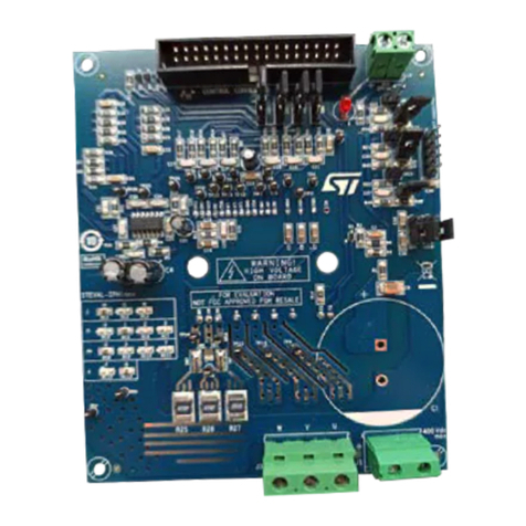
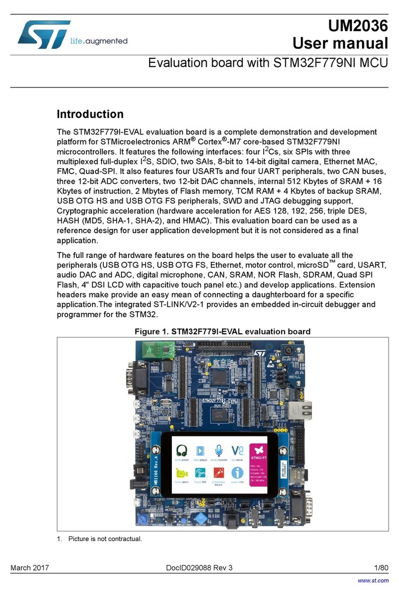
ST STUSB02E User manual

June 2008 Rev 1 1/29
UM0529
User manual
STUSB02E and STUSB03 low-speed
evaluation boards: STEVAL-PCC004V1 and STEVAL-PCC003V1
Introduction
This user manual explains the details of both the STUSB02E and STUSB03 USB low-speed
evaluation boards.
For evaluation purposes, the USB microcontroller used is the ST72F63B.
The STUSB02E or STUSB03 connected with a USB controller is ideal for use in mobile
phones, digital cameras, printers, PDAs, etc.
The STUSB02E or STUSB03 USB low-speed evaluation board is designed for
demonstration and evaluation purposes.
■Reference:
– STEVAL-PCC003V1: low-speed USB evaluation board based on the STUSB03
transceiver and ST72F63B
– STEVAL-PCC004V1: low-speed USB evaluation board based on the STUSB02E
transceiver and ST72F63B
Figure 1. USB low-speed evaluation board - STEVAL-PCC003V1
www.st.com
www.BDTIC.com/ST

Contents UM0529
2/29
Contents
1 Getting started . . . . . . . . . . . . . . . . . . . . . . . . . . . . . . . . . . . . . . . . . . . . . . 6
1.1 Package contents . . . . . . . . . . . . . . . . . . . . . . . . . . . . . . . . . . . . . . . . . . . . 6
1.1.1 Hardware . . . . . . . . . . . . . . . . . . . . . . . . . . . . . . . . . . . . . . . . . . . . . . . . . 6
1.1.2 Software . . . . . . . . . . . . . . . . . . . . . . . . . . . . . . . . . . . . . . . . . . . . . . . . . . 6
1.1.3 Documentation . . . . . . . . . . . . . . . . . . . . . . . . . . . . . . . . . . . . . . . . . . . . . 6
1.2 Hardware installation . . . . . . . . . . . . . . . . . . . . . . . . . . . . . . . . . . . . . . . . . 6
1.2.1 Powering on the board . . . . . . . . . . . . . . . . . . . . . . . . . . . . . . . . . . . . . . . 6
1.3 Software installation . . . . . . . . . . . . . . . . . . . . . . . . . . . . . . . . . . . . . . . . . . 6
1.3.1 Drivers for evaluation board . . . . . . . . . . . . . . . . . . . . . . . . . . . . . . . . . . . 6
1.3.2 System requirements for USB HID demonstration GUI . . . . . . . . . . . . . . 6
2 Evaluation board hardware . . . . . . . . . . . . . . . . . . . . . . . . . . . . . . . . . . . 8
3 Evaluation board components . . . . . . . . . . . . . . . . . . . . . . . . . . . . . . . . . 9
3.1 Microcontroller U1 . . . . . . . . . . . . . . . . . . . . . . . . . . . . . . . . . . . . . . . . . . . 9
3.1.1 Oscillator . . . . . . . . . . . . . . . . . . . . . . . . . . . . . . . . . . . . . . . . . . . . . . . . . 9
3.2 STUSB02E/STUSB03E transceiver U5 . . . . . . . . . . . . . . . . . . . . . . . . . . . 9
3.3 74LCX139MTR low voltage dual 2-to-4 decoder/demultiplexer U2,U3 . . . 9
3.4 LD2985BM33R voltage regulator U4 . . . . . . . . . . . . . . . . . . . . . . . . . . . . 10
4 Power requirements . . . . . . . . . . . . . . . . . . . . . . . . . . . . . . . . . . . . . . . . 11
5 Pin assignments . . . . . . . . . . . . . . . . . . . . . . . . . . . . . . . . . . . . . . . . . . . 12
5.1 Jumpers details . . . . . . . . . . . . . . . . . . . . . . . . . . . . . . . . . . . . . . . . . . . . 12
5.2 Switch assignments . . . . . . . . . . . . . . . . . . . . . . . . . . . . . . . . . . . . . . . . . 14
5.3 Connector assignments . . . . . . . . . . . . . . . . . . . . . . . . . . . . . . . . . . . . . . 15
5.4 USB pin assignments . . . . . . . . . . . . . . . . . . . . . . . . . . . . . . . . . . . . . . . . 15
5.5 Decoder U2/U3 pin description . . . . . . . . . . . . . . . . . . . . . . . . . . . . . . . . 15
5.5.1 Decoder/demultiplexer U2 . . . . . . . . . . . . . . . . . . . . . . . . . . . . . . . . . . . 16
5.5.2 Decoder/demultiplexer U3 . . . . . . . . . . . . . . . . . . . . . . . . . . . . . . . . . . . 16
5.6 STUSB02E and STUSB03 transceiver pin configuration . . . . . . . . . . . . . 17
6 Firmware . . . . . . . . . . . . . . . . . . . . . . . . . . . . . . . . . . . . . . . . . . . . . . . . . 20
6.1 Communication with the application board . . . . . . . . . . . . . . . . . . . . . . . . 21
www.BDTIC.com/ST

UM0529 Contents
3/29
6.1.1 PC software control of the evaluation board . . . . . . . . . . . . . . . . . . . . . 21
6.1.2 Display of evaluation board state . . . . . . . . . . . . . . . . . . . . . . . . . . . . . . 21
6.2 USB suspend . . . . . . . . . . . . . . . . . . . . . . . . . . . . . . . . . . . . . . . . . . . . . . 22
7 Schematics . . . . . . . . . . . . . . . . . . . . . . . . . . . . . . . . . . . . . . . . . . . . . . . 23
8 Bill of material . . . . . . . . . . . . . . . . . . . . . . . . . . . . . . . . . . . . . . . . . . . . . 24
Appendix A Port configuration . . . . . . . . . . . . . . . . . . . . . . . . . . . . . . . . . . . . . . . 26
Appendix B Abbreviations . . . . . . . . . . . . . . . . . . . . . . . . . . . . . . . . . . . . . . . . . . . 27
9 Revision history . . . . . . . . . . . . . . . . . . . . . . . . . . . . . . . . . . . . . . . . . . . 28
www.BDTIC.com/ST

List of figures UM0529
4/29
List of figures
Figure 1. USB low-speed evaluation board - STEVAL-PCC003V1 . . . . . . . . . . . . . . . . . . . . . . . . . . . 1
Figure 2. STUSB02E/STUSB03E- low-speed evaluation board enumeration in GUI . . . . . . . . . . . . . 7
Figure 3. STUSB02E/ STUSB03 evaluation board block diagram . . . . . . . . . . . . . . . . . . . . . . . . . . . 8
Figure 4. STUSB02E/STUSB03E evaluation board enumeration . . . . . . . . . . . . . . . . . . . . . . . . . . . 20
Figure 5. STUSB02E/ STUSB03 evaluation board demonstration . . . . . . . . . . . . . . . . . . . . . . . . . . 21
Figure 6. STUSB02E/STUSB03E evaluation board schematic . . . . . . . . . . . . . . . . . . . . . . . . . . . . . 23
www.BDTIC.com/ST

UM0529 List of tables
5/29
List of tables
Table 1. Microcontroller details. . . . . . . . . . . . . . . . . . . . . . . . . . . . . . . . . . . . . . . . . . . . . . . . . . . . . . 9
Table 2. General jumper assignments . . . . . . . . . . . . . . . . . . . . . . . . . . . . . . . . . . . . . . . . . . . . . . . 12
Table 3. Voltage regulator U4 related jumper assignment . . . . . . . . . . . . . . . . . . . . . . . . . . . . . . . . 12
Table 4. USB transceiver U5 related jumper assignment . . . . . . . . . . . . . . . . . . . . . . . . . . . . . . . . . 13
Table 5. CONFIG section related jumper assignment . . . . . . . . . . . . . . . . . . . . . . . . . . . . . . . . . . . 14
Table 6. Evaluation board switch assignments. . . . . . . . . . . . . . . . . . . . . . . . . . . . . . . . . . . . . . . . . 14
Table 7. Evaluation board connectors . . . . . . . . . . . . . . . . . . . . . . . . . . . . . . . . . . . . . . . . . . . . . . . 15
Table 8. USB mini-B pin assignments . . . . . . . . . . . . . . . . . . . . . . . . . . . . . . . . . . . . . . . . . . . . . . . 15
Table 9. Decoder pin U2/ U3 description . . . . . . . . . . . . . . . . . . . . . . . . . . . . . . . . . . . . . . . . . . . . . 15
Table 10. Truth table for first input of U2 . . . . . . . . . . . . . . . . . . . . . . . . . . . . . . . . . . . . . . . . . . . . . . 16
Table 11. Truth table for second input of U2 . . . . . . . . . . . . . . . . . . . . . . . . . . . . . . . . . . . . . . . . . . . 16
Table 12. Truth table for first input of U3 . . . . . . . . . . . . . . . . . . . . . . . . . . . . . . . . . . . . . . . . . . . . . . 16
Table 13. Truth table for second input of U3 . . . . . . . . . . . . . . . . . . . . . . . . . . . . . . . . . . . . . . . . . . . 17
Table 14. Pin description for STUSB02E transceiver . . . . . . . . . . . . . . . . . . . . . . . . . . . . . . . . . . . . . 17
Table 15. Pin description for STUSB03 transceiver . . . . . . . . . . . . . . . . . . . . . . . . . . . . . . . . . . . . . . 18
Table 16. BOM list . . . . . . . . . . . . . . . . . . . . . . . . . . . . . . . . . . . . . . . . . . . . . . . . . . . . . . . . . . . . . . . 24
Table 17. Port configuration . . . . . . . . . . . . . . . . . . . . . . . . . . . . . . . . . . . . . . . . . . . . . . . . . . . . . . . . 26
Table 18. Abbreviations . . . . . . . . . . . . . . . . . . . . . . . . . . . . . . . . . . . . . . . . . . . . . . . . . . . . . . . . . . . 27
Table 19. Document revision history . . . . . . . . . . . . . . . . . . . . . . . . . . . . . . . . . . . . . . . . . . . . . . . . . 28
www.BDTIC.com/ST

Getting started UM0529
6/29
1 Getting started
1.1 Package contents
The STUSB02E and STUSB03 evaluation board kit package comprises the following:
1.1.1 Hardware
●STUSB02E / STUSB03 - low-speed evaluation board
●USB to mini-B cable
1.1.2 Software
●USB HID demonstration GUI
1.1.3 Documentation
●User manual
●Detailed presentation of applications and STUSB02EQR / STUSB03EQR features
1.2 Hardware installation
1.2.1 Powering on the board
Connect the evaluation board to the PC using the J7 connector via the USB to mini-B cable.
The power status LED D2 lights up indicating successful power-up of the board.
1.3 Software installation
To work with the STUSB02E or STUSB03 low-speed evaluation board, install the USB HID
demonstration GUI on the PC.
1.3.1 Drivers for evaluation board
The firmware programmed in the evaluation board is based on HID class of USB. Windows
OS have built-in drivers for HID functionality
1.3.2 System requirements for USB HID demonstration GUI
For low-speed evaluation board communication with GUI, a recent version of Windows, such
as Windows 2000 or Windows XP must be installed on the PC.
Windows is a registered trademark of Microsoft Corporation in the United States and other
countries.
Note: The version of the Windows OS installed on your PC can be determined by clicking on the
system icon in the control panel.
After successful installation of USB HID demonstration GUI and board connection to PC,
open the USB HID demonstration GUI. The low-speed evaluation board is enumerated in
the GUI as shown in Figure 2.
www.BDTIC.com/ST

Evaluation board hardware UM0529
8/29
2 Evaluation board hardware
All the hardware components except the transceiver IC are the same for the STUSB02E and
STUSB03 evaluation boards. The evaluation boards are comprised of one mini-B USB
connector, one USB controller, one USB transceiver, two 2-to-4 demultiplexers and all
required discrete components (pull-up resistors, series resistors and power supply
capacitors). The device can be configured through a set of jumpers and the main signals
can be accessed through test points.
The evaluation board is powered from a USB mini-B or optionally from an external supply.
The transceiver STUSB02EQR/ STUSB03EQR is connected at the USB communication
lines of the microcontroller. The USBVCC 3.3 V is obtained from the controller for providing
the VIF to the transceiver and also the supply to 74LCX139. Since the ST72F63B is a USB
low-speed microcontroller, therefore the pull-up resistor is connected to the D- pin of the
transceiver. Hence, STUSB02E / STUSB03 acts as a low-speed transceiver. Also the SPD
pin of the transceiver is connected to GND for low-speed selection.
The 74LCX139MTR is used to convert 5 V signals from the microcontroller to 3.3 V signals
to STUSB02E/STUSB03E. This device is used because some signals need polarity
conversion whereas other signals just need the level conversion. This is explained in
Section 3.3: 74LCX139MTR low voltage dual 2-to-4 decoder/demultiplexer U2,U3.
Figure 3. STUSB02E/ STUSB03 evaluation board block diagram
STUSB02E/
STUSB03E
USB LS
Transceiver
U5
Power pins(V
BUS
, V
IF
)
V
BUS
, DP, DM
ST72F63B
USB
Controller
U1
LEDs
Switches
Mini-B
connector
74LCX139MTR
U2
74LCX139MTR
U3
Configuration
Jumpers
Signals
at 3.3V
Signals
at 5V
www.BDTIC.com/ST

UM0529 Evaluation board components
9/29
3 Evaluation board components
3.1 Microcontroller U1
The microcontroller used for the STUSB02E/STUSB03E transceiver evaluation board is
ST72F63B. It is programmed with firmware to support the USB HID functionality for
demonstration purposes.
3.1.1 Oscillator
A 12 MHz crystal is used for providing the necessary clock to the microcontroller. C3 and C4
capacitors are used along with a quartz crystal.
3.2 STUSB02E/STUSB03E transceiver U5
The STUSB02E and STUSB03 are single chip USB transceivers that support both USB full-
speed and USB low-speed operations. Both have an integrated 5 V to 3.3 V regulator which
allows direct powering from the VBUS. The transceivers also support sharing mode when
VBUS is not present which allows the D+/D- lines to be shared with other serial protocols.
They are also designed to operate down to 1.6 V so that they are compatible with lower
system voltages of most portable systems, which include PDAs, MP3 players and cell
phones.
3.3 74LCX139MTR low voltage dual 2-to-4 decoder/demultiplexer
U2,U3
The 74LCX139MTR is a low-voltage CMOS dual 2-to-4 line decoder/ demultiplexer. It is
ideal for low-power and high-speed 3.3 V applications. It can be interfaced to 5 V signal
environment for inputs. The active low enable input can be used for gating or as a data input
for demultiplexing applications. While the enable input is held high, all four outputs are high
independently of the other inputs.
It has the same speed performance at 3.3 V as well as the 5 V, combined with lower power
consumption. All inputs and outputs are equipped with protection circuits against static
discharge, giving them 2 KV ESD immunity and transient excess voltage.
As explained above this device is used for interfacing between the microcontroller and
STUSB02/STUSB03E for 5 V to 3.3 V signals. The 74LVX139MTR device can also be used
as it also has 5 V tolerant inputs.
Note: The 74LCX139MTR is used for interfacing the ST72F63B microcontroller with an operating
voltage ranging from 4 V to 5.5 V in the evaluation board to transceiver. In the final
Table 1. Microcontroller details
Feature Description
Sales type ST72F63BK4B1
Package PSDIP32
Operating voltage 4.0 V to 5.5 V
www.BDTIC.com/ST

Evaluation board components UM0529
10/29
application involving the USB02E/USB03E, such a voltage converter is not needed as the
USB microcontroller will have the VIF ranging from 1.6 V to 3.3 V as required for the
transceiver. Also, we need signal inversion for the USBOE and SUS signals of transceiver.
This task is also performed by the 74LCX139MTR in this board. Hence, 74LCX139MTR
usage is basically microcontroller specific.
3.4 LD2985BM33R voltage regulator U4
The LD2985BM33R is a 150 mA fixed output voltage regulator. The ultra-low drop voltage
and the low quiescent current make them particularly suitable for low-noise, low-power
applications and in battery-powered systems. In sleep mode, quiescent current is less than
1 µA when the INHIBIT pin is pulled low. Shutdown logic control function is available on pin
3 (TTL compatible).
Note: LD2985BM33R usage is optional in the board. By configuring jumpers J9,J13,J11, the
external voltage regulator can be switched off. In this case, the internal voltage regulator of
the microcontroller is used to power 74LCX139MTR and STUSB02E/ STUSB03 VIF
.
When external voltage regulator LD2985BM33R is used for powering 74LCX139MTR and
STUSB02E/ STUSB03 VIF , overall current consumption of the board increases.
www.BDTIC.com/ST

UM0529 Power requirements
11/29
4 Power requirements
The recommended supply voltages for the STUSB02E/STUSB03E USB transceivers are
the following:
1. VIF = 1.6 - 3.6 V (typical value: VIF = 1.8 V)
2. VBUS = 4.0 - 5.5 V (typical value: VBUS = 5 V)
The VIF for the USB transceiver can be obtained from the onboard voltage regulator as well
as the built-in voltage regulator of the ST72F63B.
Both evaluation boards are designed for two power supply configurations. It can be bus
powered from the mini-B connector. There is another option available for powering the
board using the J3 connector. J3 can be used for powering the board from an external
supply. There is a three-pin jumper J4 on the board which selects the power supply
configuration.
www.BDTIC.com/ST

Pin assignments UM0529
12/29
5 Pin assignments
5.1 Jumpers details
Ta bl e 2 , 3, and 4show jumper assignments of the demonstration board. All the jumper
settings are same for both the STUSB02E and STUSB03 evaluation boards except for
jumper J10 and J12.
Table 2. General jumper assignments
Jumper Related pin(s) Description Default
JP1 PB7 Open: disconnects LED D1 from the microcontroller pin
connected to it. Closed
JP2 PB6 Open: disconnects LED D2 from the microcontroller pin
connected to it. Closed
JP3 PA7 Open: disconnects LED D3 from the microcontroller pin
connected to it. Closed
JP4 PA6 Open: disconnects LED D4 from the microcontroller pin
connected to it. Closed
J8 OSCIN Closed: connects main clock input for external source. Open
Table 3. Voltage regulator U4 related jumper assignment
Jumper Related pin(s) Description Default
J9 VIN
Open: disconnects the external voltage regulator supply
voltage
Closed: connects the VCC to IN pin of voltage regulator
U4 when external regulator is to be used.
Open
J13 INH
Pin 1 and 2 closed: connects the INHIBIT of U4 to VCC
to switch on the external voltage regulator U4
Pin 2 and 3 closed: connects the INHIBIT pin of U4 to
GND to switch off the external voltage regulator U4.
Pin 2 and
3 closed
www.BDTIC.com/ST

UM0529 Pin assignments
13/29
Note: J12 is applicable only to the STUSB03 evaluation board. It is not applicable to the
STUSB02E evaluation board since RSL is NC in the STUSB02E.
Table 4. USB transceiver U5 related jumper assignment
Jumper Related
pin(s) Description Default
JP5 USBVCC
Closed: connects USBVCC (=3.3V) to VIF in
USB02E/ USB03E transceiver.
Open: disconnects USBVCC to VIF in USB02E/
USB03E transceiver.
Closed
JP6 VBUS Closed: connects USB02E/USB03E transceiver
VBUS pin to VCC supply. Closed
J4(three pin
connector) VBUS
Pin 2 and 3 closed: connects the VBUS supply
to different components like microcontroller,
decoder etc.
Pin 1 and 2 closed: used for powering the
board through an external supply.
Pin 2 and 3 closed
J10 VPU
Pin 1 and 2 closed: connects the 1.5 kΩ
resistor between D- and VPU pin of USB
transceiver for low-speed mode.
Pin 2 and 3 closed: connects the 1.5 kΩ
resistor between D- and VTRM pin of USB
transceiver
Pin 2 and 3 closed for
STUSB03 evaluation
board.
(STEVAL-PCC003V1)
Pin 1 and 2 closed for
STUSB02E evaluation
board.
(STEVAL-PCC004V1)
J11 3V3 SEL
Pin 1 and 2 closed: connects the U4 O/P to
3.3 V VCC
Pin 2 and 3 closed: connects USB VCC to 3.3 V
VCC
Pin 2 and 3 closed
J12 RSL
Pin 1 and 2 closed: connects the RSL of U5 to
GND
Pin 2 and 3 closed: connects the RSL of U5 to
VIF
Pin 1 and 2 closed for
STUSB03 evaluation
board
(STEVAL-PCC003V1)
Open for STUSB02E
evaluation board
(STEVAL-PCC004V1)
www.BDTIC.com/ST

Pin assignments UM0529
14/29
CONFIG section jumpers are provided for future user requirements.
5.2 Switch assignments
Tabl e 6 shows switch assignments of the demonstration board.
Table 5. CONFIG section related jumper assignment
Jumper Related pin(s) Description Default
J14 CFG1_PB5
Pin 1 and 2 closed: connects the CFG1_PB5
to GND
Pin 2 and 3 closed: connects the CFG1_PB5
to VCC
Open
J15 CFG2_PB1
Pin 1 and 2 closed: connects the CFG2_PB1
to GND
Pin 2 and 3 closed: connects the CFG2_PB1
to VCC
Open
J16 CFG3_PA0
Pin 1 and 2 closed: connects the CFG3_PA0
to GND
Pin 2 and 3 closed: connects the CFG3_PA0
to VCC
Open
J17 CFG4_PC0
Pin 1 and 2 closed: connects the CFG4_PC0
to GND
Pin 2 and 3 closed: connects the CFG4_PC0
to VCC
Open
Table 6. Evaluation board switch assignments
Jumper Related pin(s) Description)
SW1 RESET When button is pressed, the active low signal forces the
initialization of the MCU.
SW2 PA3 When button is pressed, PA3 microcontroller pin is connected
to ground. Not used at present.
SW3 PA4 When button is pressed, PA4 microcontroller pin is connected
to ground. Not used at present.
SW4 PA5
When button is pressed, PA5 microcontroller pin is connected
to ground. This is used to control the button state on the USB
demonstrator software.
www.BDTIC.com/ST

UM0529 Pin assignments
15/29
5.3 Connector assignments
Tabl e 7 shows connector assignments of the evaluation board connectors.
5.4 USB pin assignments
Tabl e 8 shows USB mini-B connector pin assignments.
5.5 Decoder U2/U3 pin description
Tabl e 9 shows the pin description of the decoder.
Table 7. Evaluation board connectors
Connector Description
J7 USB mini-B connector
J3 External power supply(5 V), GND
Table 8. USB mini-B pin assignments
Pin no. Description
1V
BUS – connect a 5 V supply voltage when powering VBUS pin from mini-B connector.
2 D+ – data line
3 D- – data line
4 ID – not used
5 GND – ground reference
Table 9. Decoder pin U2/ U3 description
Pin no Symbol Name and function
1, 15 n1G, n2G Enable inputs
2, 3 1A, 1B Address inputs
4, 5, 6, 7 n1Y0 to n1Y3 Outputs
12, 11, 10, 9 n2Y0 to n2Y3 Outputs
14, 13 2A, 2B Address Inputs
8 GND Ground (0 V)
16 VCC Positive supply voltage
www.BDTIC.com/ST

Pin assignments UM0529
16/29
5.5.1 Decoder/demultiplexer U2
Ta bl e 1 0 shows the truth table for the first input of U2.
Thus, it can be seen by comparing column 3 (input 1A) and column 5 (output Y1), that the
USBOE signal is getting inverted.
Ta bl e 1 1 shows the truth table for the second input of U2.
Thus, it can be seen by comparing column 3 (input 2A) and column 4 (output Y0), that the
SUS signal is getting buffered. Hence only the voltage level conversion from 5 V to 3.3 V is
done.
5.5.2 Decoder/demultiplexer U3
The first input and other related input pins are not connected in this decoder. Ta b le 1 3
shows the truth table for second input of U3.
Table 10. Truth table for first input of U2
Inputs Outputs
Enable Select
n1G(1) 1B(3) = GND 1A(2)= USBOE nY0(4) = NC nY1 (5) = nUSBOE nY2(6)= NC nY3(7) = NC
HX X H H H H
LL L L H H H
LL H H L H H
Table 11. Truth table for second input of U2
Inputs Outputs
Enable Select
n2G(15) 2B(13)=GND 2A(14) = SUS_5 nY0(12) =SUS_33 nY1(11)= NC nY2(10) = NC nY3(9) = NC
Hx X H H H H
LL L L H H H
LL H H L H H
Table 12. Truth table for first input of U3
Inputs Outputs
Enable Select
N1G(1) 1B(3) = GND 1A(24) = CON-5V nY0(4) =CON-3V3 nY1(5) = NC nY2(6) = NC nY3(7) = NC
Hx X H H H H
LL L L H H H
LL H H L H H
www.BDTIC.com/ST

UM0529 Pin assignments
17/29
Thus it can be seen by comparing column 3 (input 1A) and column 4 (output Y0), that the
CON signal is getting buffered. Hence only the voltage level conversion from 5 V to 3.3 V is
done.
Note: Second input of U3 is not used in the application. However, to save the current consumption,
these inputs are not left floating and are tied to ground.
5.6 STUSB02E and STUSB03 transceiver pin configuration
Ta bl e 1 4 shows the pin description of STUSB02E transceiver.
Table 13. Truth table for second input of U3
Inputs Outputs
Enable Select
n2G(15)=VCC 2B(13)=GND 2A(14) = GND nY0(12) =NC nY1(11)= NC nY2(10) = NC nY3(9) = NC
Hx X H HHH
LL L L HHH
LL H H LHH
Table 14. Pin description for STUSB02E transceiver
Pin no. Symbol I/O Name and function
0 N.C Not connected
1 SPD I Edge rate control. A logic HIGH operates at edge rates for “full-speed”
operation. A logic LOW operates edge rates for “low-speed” operation.
2 RCV O Receive data. Output for USB differential data.
3VPI/O
If OE# = H, VP = receiver output (+)
If OE# = L, VP = driver input (+)
4VMI/O
If OE# = H, VM = receiver output (-)
If OE# = L, VM = driver input (-)
5CONI
CONNECT (input). Controls state of VPU. Refer to VPU pin description for
details.
6 GND Ground reference
7 SUS I Suspend (active-high). Turns off internal circuits to reduce supply current.
8 N.C. Not connected
9OE#I
Output enable (active-low). Enables transceiver data transmission to the
bus.
When not active, the transceiver is in the receive mode.
10, 11 D-, D+ I/O Differential data lines.
12 VTRM O 3.3 V reference supply output. Requires a 1.0 µF decoupling capacitor for
stability.
www.BDTIC.com/ST

Pin assignments UM0529
18/29
Ta bl e 1 5 shows the pin description of the STUSB03 transceiver.
Pin no. Symbol I/O Name and function
13 VPU O
Pull-up supply voltage output. Used to connect 1.5 kΩpull-up speed detect
resistor. If CON = 0, VPU is high impedance. If CON = 1, VPU = 3.3 V
±10%.
14 VBUS I USB bus supply voltage (4 V to 5.5 V). Supplies power to the USB
transceiver and internal circuitry.
15 VIF I System interface supply voltage (1.6 V To 3.6 V). Provides reference
supply voltage for system I/O interface signals.
16 VBUSDET O VBUS indicator output. When VBUS > 2.9 V, VBUSDET = high and when
< 2.2 V, VBUSDET = low.
Table 14. Pin description for STUSB02E transceiver (continued)
Table 15. Pin description for STUSB03 transceiver
Pin no. Symbol I/O Name and function
1 SPD I Edge rate control. A logic HIGH operates at edge rates for “full speed”
operation. A logic LOW operates edge rates for “low speed” operation.
2 RCV O Receive data. Output for USB differential data.
3VPI/O
If OE# = H, VP = receiver output (+)
If OE# = L, VP = driver input (+)
4VMI/O
If OE# = H, VM = receiver output (-)
If OE# = L, VM = driver input (-)
5CONI
CONNECT (input). Controls state of VPU. Refer to VPU pin description for
detail.
6 GND Ground reference
7 SUS I Suspend (active-high). Turns off internal circuits to reduce supply current.
8RSLI
Full speed pull-up resistor selection input. If RSEL = 0 the internal pull-up
resistor connected to D+ is disabled and an external resistor connected to
VPU pin must be used.
9OE#I
Output enable (active-low). Enables transceiver data transmission onto the
bus. When not active, the transceiver is in the receive mode.
10, 11 D-, D+ I/O Differential data lines.
12 VTRM O 3.3 V reference supply output. Requires a 1.0 µF decoupling capacitor for
stability.
13 VPU O
Pull-up supply voltage output. Used to connect 1.5 kΩpull-up speed
detect resistor. If CON = 0, VPU is high impedance. If CON = 1, VPU = 3.3
V ±10%.
www.BDTIC.com/ST

UM0529 Pin assignments
19/29
Refer to the relevant datasheet of the device for a detailed description.
Pin no. Symbol I/O Name and function
14 VBUS I USB bus supply voltage (4 V to 5.5 V). Supplies power to the USB
transceiver and internal circuitry.
15 VIF I System interface supply voltage (1.6 V To 3.6 V). Provides reference
supply voltage for system I/O interface signals.
16 VBUSDET O VBUS indicator output. When VBUS > 2.9 V, VBUSDET = high and when
< 2.2V , VBUSDET = low.
EXP N.C. Not Connected
Table 15. Pin description for STUSB03 transceiver (continued)
www.BDTIC.com/ST

Firmware UM0529
20/29
6 Firmware
The demo-application consists of an HID demonstrator GUI running on the PC and HID
class demonstration firmware running on the board. The PC software and the firmware
running on the USB microcontroller provide a clear example of data exchange between the
PC and the board. The USB signals are routed through the STUSB02E/STUSB03E
transceiver. The ST72F63B firmware is based on a USB core library that does all the
hardware control of the USB interface. This application board incorporates basic input
sources such as push-buttons, trimmers or output devices (LEDs) and a wrap area.
Communications between the PC and the ST7 board are done through different USB pipes:
●control IN and OUT during the enumeration with the bi-directional endpoint 0
●interrupt IN from endpoint 1 for data transferred from ST7 to PC
●interrupt OUT to the endpoint 2 for the data transferred from PC to ST7
The evaluation board must first be connected to the PC with the USB cable. As a result, the
evaluation board is enumerated as a HID device as shown in Figure 4 and is ready to use.
Figure 4. STUSB02E/STUSB03E evaluation board enumeration
By starting the HID demonstrator on the PC, you get a graphical interface for controlling the
application board. This PC software is used to demonstrate the enumeration process and
www.BDTIC.com/ST
Other manuals for STUSB02E
1
This manual suits for next models
3
Table of contents
Other ST Motherboard manuals

ST
ST STM32100B-EVAL User manual

ST
ST EVAL-L9963E-MCU User manual

ST
ST M24LR64-R User manual

ST
ST EVALSPEAr320CPU User manual

ST
ST STEVAL-IHM015V1 User manual

ST
ST NUCLEO-F207ZG User manual

ST
ST SPC5-UDESTK User manual

ST
ST STM32100E-EVAL User manual

ST
ST STEVAL-L99615C User manual

ST
ST Teseo-VIC3DA User manual

ST
ST STLINK-V3SEGT User manual

ST
ST STEVAL-TSP009V2 Administrator Guide

ST
ST STEVAL-BLUEPIRV1 User manual

ST
ST EVAL-7803APSO-SA User manual

ST
ST STM3210E-EVAL User manual

ST
ST STM32G4 Nucleo-64 User manual

ST
ST STM32L152RCT6 Discovery kit User manual

ST
ST STM32F3DISCOVERY User manual

ST
ST SPC58XXMB User manual

ST
ST PTB801DC User manual