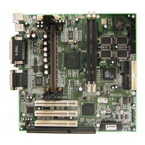
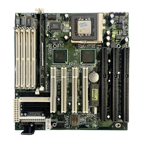
A-Trend ATC-6130E User manual

CONTENTS
COMPONENT LOCATION DIAGRAM...................................A
CHECK LIST OF THE PACKAGING ......................................B
TABLE OF CONTENTS..............................................................1
HOW TO USE THIS MANUAL..................................................2
CH
APTER 1 Introduct on................................................................3
1-1 System features.................................................................................3
1-2 Software Power Off Control.............................................................4
1-3 SB-Link Sideband Signals JP5).……………………………..….. 4
1-4 Wake-On-LAN……………………….…………..……....……….. 5
1-5 Keyboard & PS/2 Mouse Power On……………………………… 6
1-6 Thermister option)……………………………………………..… 6
1-7 LDCM LANDesk Client Manager, option)……………...………7
CHAPTER 2 Installat on............................................................8
2-1 Installation Procedure .....................................................................8
2-2 CPU Installation.............................................................................. 9
2-2-1 CPU Setting…………………………………………………….10
2-3 System Memory Installation...........................................................11
2-4 Connectors Description..................................................................12
2-5 IDE Driver Installation...................................................................17
CHAPTER 3 Award BIOS Setup.............................................18
3-1 Update BIOS Procedure.................................................................19
3-1-1 Update PentiumII microcode API…………………………….20
3-2 Award System BIOS Configuration Setup....................................21
Append x A How to Install Pent umII、Celeron and Processors
w th SECC2 Package?
Append x B How to Setup Therm ster ?
Append x C Techn cal Support Request Form
1

HOW TO USE THIS MANUAL
To obtain maximum use from this manual it is suggested:
ead Page A COMPONENT LOCATION DIAG AM where you find the
mainboard layout diagram. Please refer to it when you configure the system.
ead Page B CHECK LIST OF THE PACKAGING where you find the packing
contents.
Read about an overview of the mainboard features, and how to upgrade as well
as to change hardware configurations such as memory size, CPU type, jumper
settings lists and connectors in the following categories
Chapter 1 Introduction
Chapter 2 Installation
When you have finished reading of both chapter 1 and chapter 2, turn to Chapter
3 Award BIOS Setup where you will find the update BIOS procedure and the
further information which is stored in the SETUP is the system hardware
configuration.
The back of this manual contains APPENDIX A which shows you how to setup
PentiumII & Celeron and processors with SECC2 package, APPENDIX B
which shows you how to setup thermister and APPENDIX C which is a list of
request form for technical support.
Your system dealer will set up the mainboard according to your demand of the
computer. It means that the current settings of your mainboard may not be the
same as the defaults shown in this user's manual. If you need to change your
configuration, please ask your dealer first. Be sure this will not void your system
warranty, or ask your dealer to do it for you.
REMARK
Intel® is a registered trademark of Intel Corporation.
All other brands and product names are trademarks registered trademarks of their respective companies.
2

CHAPTER 1 INTRODUCTION
1-1 ATC-6130E Ma nboard System Features
Intel Pentium®II CPU & CeleronTM CPU operating from 233MHz to 400MHz .
Intel 82440EX AGPset.
Two 3.3V 168-pin DIMM sockets in two banks of 64-bit wide path up to 256MB
SDRAM or 512MB EDO DRAM with parity chip ECC support).
Built-in Switching Voltage Regulator.
Auto-detect CPU core voltage range from 1.8V to 3.5V.
One AGP slot, three 32-bit PCI slots with revision 2.1 and two 16-bit ISA slots.
Dual Master IDE connectors support Ultra DMA/33 33MB/sec), up to four devices in
two channels for connecting of high capacity hard drive, CD-ROM, Zip, LS-120...etc.
Winbond 83977 high-speed Ultra Multi-I/O chipset.
USB Universal Serial Bus) header supporting up to 127 peripheral devices.
AT style Keyboard Connector and PS/2 Mouse Header.
AT Power Connector and ATX Power Connector.
Infrared Transfer IrDA TX/RX) Connection.
One FDC Port supporting two devices up to 2.88MB.
Two 16550A fast UARTs compatible Serial Ports.
One EPP/ECP Mode Parallel Printer Port.
Fan On / Off Control, Power Button , Resume Reset and Modem Ring On ,Software
Power Off Control, Wake-On-LAN, Keyboard & PS/2 mouse Power On. with ATX
power)
Built-in Hardware Health Monitoring. option)
Intel LDCM software. option)
Baby AT form factor, board dimension is 260mm x 220mm 8.66” x7.33” ).
3

1-2 Software Power Off Control
The mainboard design supports Software Power Off Control feature through the SMM
code in the BIOS under Windows 95/98, Windows 3.1x, and MS-DOS operation system
environment. In order to reach this feature, you should use ATX power supply.
First, you should connect the power switch cable to the connector “PS-ON” on the
mainboard. In the BIOS screen of ‘POWER MANAGEMENT SETUP’, choose “User
Defined” or “Min. Power Saving” or “Max. Power Saving”) in ‘Power Manager’ and
choose “Yes” in ‘PM Control by APM’.
In Windows 95/98, if you would like to power off the system, you just choose
“shutdown the computer ?” in the “Shut Down Windows“ from Windows 95/98, then the
system power will be off directly and become the stand-by status. In the mean time, you
will find the power LED light is blinking. If you would like to restart the system, just
press the power switch button, and the system will be powered on.
Note : If you will leave your system for several days, we suggest you use hardware power
off to shutdown your system.
1-3 SB-L nk S deband S gnals (JP5)
In order to migrate the legacy Sound Blaster compatible audio to the PCI bus, EMU8008
incorporates a pair of SB-Link request/grant sideband signals PCPCIR EQN and
PCPCIGNTN) to interface to the PCI bus. SB-Link is a mechanism that was defined and
developed by INTEL as a docking solution which allows ISA slots to exist in docking
stations connected to desktop PC PCI bus.
DIMMs JP5 2x3 sideband header, sound will also
has a 2x3 header and a cable.
4
SIR
REQ
GN

1-4 Wake-On-LAN
The remote Wake-On-LAN mode of operation is a mechanism that uses Advanced
Micro Device Magic Packet technology to power up a sleeping workstation on the
network. This mechanism is accomplished when the LAN card receives a specific packet
of information, called a Magic Packet, addressed to thenode on the network. For
additional protection, Secure ON is an optional security feature that can be added to the
Magic Packet that requires a password to power up the sleeping workstation. When the
LAN card is in remote Wake-On-LAN mode, main system power can be shut down
leaving power only for the LAN card and auxiliary power recondition.
The LAN card performs no network activities while in the remote Wake-On-LAN mode
of operation-It only monitors the network for receipt of a Magic Packet. If a Magic Packet
is addressed to the LAN card on the network, the LAN card wake up the system. If the
Secure ON feature has been enabled, the password added to the Magic Packet is also
verified prior to waking up the system.
CAUTION :
It needs to use with the ATX power supply revision 2.1 ( which can deliver
+5V standby ±5% at 720mA ) and the LAN card supports WOL function with
INTEL protocol.
ISA slots
WOL
5

1-5 Keyboard & PS/2 Mouse Power On
The ATC-6130E mainboard has two easy and convenient ways to power up the system.
Users may power on the system by typing a password or by double-clicking the PS/2 mouse
on the left or right button. It just depends on which one users set in the “Power On function”
of BIOS INTEGRANTED PERIPHERALS. And this function is available for ATX power
supply only.
In order to satisfy different users that will have many different needs, the ATC-6130E
mainboard provides four different methods to power up the system:
1. KB Power On Password:
The setting process is as follow: Password: when users select this option, it will show
“Enter Password:”. After users type the password, it will show “ Confirm Password:”
and users have to type the same password to confirm it now. Under power-off
condition, if users type the correct password, the system will be powered on
immediately.
If you have set the keyboard password power on function, but lost the password, you
can CLEAR CMOS to clear the password. Or you can’t power on the system.
2. Hot Key Power On:
When users select this option, it will show another line below as Hot Key Power ON :
“Ctrl-F1”.You can select from “Ctrl-F1” to “Ctrl-F12” by using PageUp / PageDown
keys. After power off, users can hold down both the Ctrl and F1 keys to power up the
system.
3. Mouse Left, Mouse R ght :
This function is available for PS/2 mouse only. It will power up the system by double
clicking the left or right mouse. Note that do not move the mouse when you click. Or
you can’t power on the system.
4. BUTTON ONLY :
Only the power button can power on the system.
1-6 Therm ster (opt on)
This means that user can monitor the CPU temperature through thermister.
When setting up the thermister, the Bios will load the CPU temperature automatically.
There is a choice of the warning beep sound if the user set the option on. If the CPU
temperature is overheated, the user will get the notice from the thermister. This time you
should shut down computer and check your devices. Or you can connect with you dealer.
6

1-7 LDCM (LANDesk Cl ent Manager)(opt on)
If ATC-6130E built-in hardware component support Intel LDCM. LDCM can satisfy
users who want manageable systems that can interact automatically with the user. Client
manager is the answer, enabling both administrators and clients to manage systems. The
features of LDCM are as following :
※Rev ew system nventory
Client Manager enables you to view hundreds of inventoried items. Some of these items
are software related, while many others are hardware related.
※V ew DMI-compl ant component nformat on
Client manager enables you to view component information that is compliant with the
Desktop Manager Interface(DMI). This means you can manage third-party DMI-
compliant components not included with Client manager.
※Back up and restore system conf gurat on f les.
Client Manager enables you back up and restore system configuration files.
Whenever you plan on changing the system configuration , you can make a backup
set. If the system no longer works correctly, after you change the system
configuration , you can simply restore the system configuration with the backup set.
※Troubleshoot
Since Client manager enables you to view the system inventory, you can easily
troubleshoot system problems.
※Rece ve not f cat ons for system events
Client manager enables you to receive notification of certain system events. For example,
if the system is running low on virtual memory, you are notified of the potential
problem.
※Transfer f les to and from cl ent workstat ons
As an administrator, you have the ability to transfer files to and from client workstation.
This is helpful, for example, when you need to update a client workstation driver.
※Remotely reboot cl ent workstat ons Administrator also have the ability to
remotely reboot a workstation. This is helpful when you want system configuration
changes to take effect.
7

CHAPTER 2 INSTALLATION
2-1 INSTALLATION PROCEDURE
Before installing the computer, please prepare all components such as CPU, DRAM;
peripherals such as hard drive, keyboard, CD-ROM and accessories such as cables.Then,
install the system as following:
1. Plug CPU/ heat sink refer to PentiumII & CeleronTM installation guide, Append x A),
and DRAM modules on the mainboard.
2. Set DIP switch & jumpers based on your configuration.
3. Plug add-on cards into PCI/ISA slots, if needed.
4. Connect cables to peripherals devices, power supply…
5. Make sure all components and devices are well connected, turn on the power and
setup System BIOS based on your configuration.
6. Install peripherals devices, add-on card drivers and test them.
7. If all of above procedures are running successfully, turn the power off and screw the
chassis cover to the chassis, and then connect external devices which are cabled to
the system.
2-2 CPU INSTALLATION
8

ATC-6130E supports INTEL Pentiumll CPU & CeleronTM CPU.
The ATC-6130E mainboard has built-in VID (Voltage Identify) function to auto
detect CPU voltages. Hence you do not have to set the CPU voltage setting.
Slot 1
SW1
ON DIP
1 2 3 4
SW1
DIP switch, i.e. : OFF, OFF, OFF, OFF)
ON : switch to the ‘ON’ position.
OFF : switch to the ‘OFF’ position.
9

2-2-1 CPU SETTING
66MHz CPU Bus Frequency
INTERNAL CPU
CLOCK SW1
233MHz (66x3.5)
266MHz (66x4.0)
300MHz (66x4.5)
333MHz (66x5.0)
366MHz (66x5.5)
400MHz (66x6.0)
Th s table s for 233~333MHz Intel Pent um II & 266~400MHz CeleronTM CPUs.
2-2-2 SW1 sett ng table:
CPU Clock
SW1 1-1 1-2 1-3 1-4
233MHz
ON
ON
ON
OFF
266MHz
OFF
OFF
OFF
OFF
300MHz
OFF
OFF
ON
OFF
333MHz
OFF
ON
OFF
OFF
366MHz
OFF
ON
ON
OFF
400MHz
ON
OFF
OFF
ON
1
1 2 3 4
1 2 3 4
ON
OFF
ON
OFF
1 2 3 4
ON
OFF
1 2 3 4
ON
OFF
1 2 3 4
ON
OFF
1 2 3 4
ON
OFF

2-3 SYSTEM MEMORY INSTALLATION
The ATC-6130E provides two 168-pin DIMM sockets for system memory expansion
from 8MB to 256MB SDRAM or 512 EDO RAM. These two DIMMs are arranged to two
banks, please refer to page A. Each bank provides 64-bit wide data path.
Bank/DIMM Memory Module Total Memory
Bank0/DIMM1 8/16/32/64/128/256MB 8MB~256MB
Bank1/DIMM2 8/16/32/64/128/256MB 8MB~256MB
Total System Memory 8MB~768MB
DRAM type, s ze, par ty supported:
EDO DRAM, Unbuffered SDRAM with SPD
Both parity or non-parity are available.
3.3V, Single/double-side, 8/16/32/64/128/256Mbytes
Max. memory size: 128MB SDRAM or 256MB EDO DRAM)
For 66MHz host bus CPUs use 12ns or faster DIMM module;.
SPD Serial Presence Detect)
This EPROM contains speed and design information of the memory module. The
mainboard may get optimal performance via accessing the data of SPD.
ECC Error Check and Correction)
This mainboard can support the ECC function while utilizing parity modules. To enable
this function, users must set “DRAM Data Integrity Mode” to “ECC” through “Chipset
Features Setup” from the BIOS setup screen. All in all, ECC’s function is to detect and
correct the errors of transfer datas.
1

2-4 CONNECTORS DESCRIPTION
The locations of following connectors are indicated in page A. When you plug a cable
into the following I/O connectors, you should have the pin 1 edge of the cable align with
the pin 1 end of the connector.
CONN1 : speaker, keyboard lock, reset, SMI,
turbo LED, and IDE LED connectors.
1
IDE-LED : IDE dev ces nd cator LED
connector. IDE-LED stays ON indicates
GND on-board IDE devices in operation. The red
+5V wire of HDD connector must be connected to
the pin which is +5V.
SPK PWR-LED KL
RST SMI TB-LED IDE-LED
+ +
SPK : speaker
Speaker
GND
GND
VCC
Power LED /KB Lock connector
Power LED +
N/C
GND power)
Keylock
GND
RST : Reset connector
Reset Signal
GND
SMI : SMI lead
GND
SMI Signal
TB-LED : Turbo LED nd cator, LED on
when system runs h gher speed
GND
+5V next to CPU)
PS ON

FAN
FAN : CPU cooling fan connector. Wire with
+12V voltage most likely red wire) must be
plugged into pin2, and GROUND wires
most likely black wires) must be plugged into
pin3. Please confirm the wire color
re-presentation with your supplier.
CAUTION: Plug wire into wrong connector will
DAMAGE fan and mainboard.
IR2 : Infrared / Fast Infrared module connector.
IR2
USB
USB : USB connector; Universal Serial Bus; this
is used to connect USB devices. Through an
optional dual head cable with a iron plane
OC0 abd OC1 are used to mention the status
of the USB power supply lines.
CAUTION:Plug wire into wrong connector
will DADMAGE USB devices and mainboard.
Keyboard : 5-pin AT style compatible keyboard
1
OC GND D1+ D1- VCC
VCC D0- D0+ GND OC
1 GND
2 +12V
3Sense
1 +5V
2 FIRRX
3 IRRX
4 GND
5 IRTX
Red wire
Black wire

connector.
PS/2 mouse : PS/2 mouse header.
pin1 : data
pin2 : N/C
pin3 : GND
pin4 : VCC
pin5 : clock
pin6 : N/C
PW1 : ATX mode +3.3/5/12V power supply connector.
PW2 : AT P8/P9) mode power supply connector.
1 10
11 20
COM1/COM2 : these two connectors are
used to connect serial port cables.
pin signal name
1 DCD
2 Serial In
3 Serial Out
4 DTR
5 GND
6 DSR
7 RTS
8 CTS
9 RI
1
1 2
3 4
5 6
7 8
9 10
1 3.3V 6 +5V 11 3.3V 16 GND
2 3.3V 7 GND 12 -12V 17 GND
3 GND 8 PWRGD 13 GND 18 -5V
4 +5V 9 5VSB 14
*
PS_ON 19 +5V
5 GND 10 +12V 15 GND 20 +5V
* PS_ON Soft-Off power control

FDC1 : this connector is used to connect the floppy
drive through a cable.
pin signal pin signal
2 RWC- 20 STEP-
4 reserved 22 Write Data
6 FDEDIN 24 Write Gate
8 Index- 26 Track 00-
10 Motor EnableA- 28 Write Protect-
12 Drive Sele.B- 30 Read Data-
14 Drive Sele.A- 32 Side 1 Sele.-
16 Motor EnableB- 34 DisketteChange
18 DIR-
All of odd pins are ground
LPT : this connector is used to connect parallel
port cable.
pin signal pin signal
1 STROBE- 10 ACK-
2 Data Bit 0 11 BUSY
3 Data Bit 1 12 PE
4 Data Bit 2 13 SLCT
5 Data Bit 3 14 Auto Feed-
6 Data Bit 4 15 ERROR-
7 Data Bit 5 16 INIT-
8 Data Bit 6 17 SLCT IN-
9 Data Bit 7
pin18 -- pin25 are ground
1
34 33
2 1
25 13
14 1

IDE1/IDE2 : these two connectors are used to
connect IDE devices through IDE cables,
a total of 4 devices can be connected.
pin signal pin signal
1 Reset IDE 21 DDRQ0 1)
2 GND 22 GND
3 Host Data 7 23 I/O Write-
4 Host Data 8 24 GND
5 Host Data 6 25 I/O Read-
6 Host Data 9 26 GND
7 Host Data 5 27 IORDY
8 Host Data 10 28 N/C
9 Host Data 4 29 DDAK0- 1-)
10 Host Data 11 30 GND
11 Host Data 3 31 IRQ14*
12 Host Data 12 32 IOCS16-
13 Host Data 2 33 Addr 1
14 Host Data 13 34 N/C
15 Host Data 1 35 Addr 0
16 Host Data 14 36 Addr 2
17 Host Data 0 37 ChipSele.1P-
18 Host Data 15 38 ChipSele.3P-
19 GND 39 Activity
20 Key 40 GND
* IDE1 : pin31 is IRQ14;
IDE2 : pin31 is IRQ15 or MIRQ0
2-5 IDE DRIVER INSTALLATION
1
40 39
4 3
2 1

The IDE driver installation procedure is the following :
Setup for Windows 95 :
1. Starting Windows 95.
2. Select “START”, “RUN”.
3. Put the d skette nto your d sk dr ve:
Type “ A:\inf.exe” to install INF.EXE.
Type “A:\WIN95\SETUP.EXE”.
Or put the CD nto your CD-ROM dr ve:
If your CD-ROM drive is D, type “ D:\winp2x4.exe”.
Then type “D:\IDE\WIN95\SETUP.EXE” to install IDE driver.
4. Restart computer, then follow the instructions on your
screen to install new IDE driver we offer in the 3.5“ diskette or CD.
5. Exit Windows 95, turn power off; then turn power on.
Setup for Windows 98 :
1. Starting Windows 98.
2. Select “START”, “RUN”.
3. Put the d skette nto your d sk dr ve:
Type “A:\WIN95\SETUP.EXE”.
Or put the CD nto your CD-ROM dr ve:
Type “D:\IDE\WIN95\SETUP.EXE” to install IDE driver.
4. Restart computer, then follow the instructions on your
screen to install new IDE driver we offer in the 3.5“ diskette or CD.
5. Exit Windows 98, turn power off; then turn power on.
The other platforms please refer to readme file.)
1

CHAPTER 3 Award BIOS SETUP
Award BIOS manufacturer provides access to the system BIOS through the hardware and
software on each ATC-6130E mainboard. The hardware consists of a Flash ROM and the
software is a group of programs that are installed in the ROMBIOS along with all the
other data the BIOS must contain.
The ATC-6130E mainboard will require special driver supplied by the manufacturer to
update the BIOS SETUP program. It is a good idea to read the next page for details for
update BIOS driver installation or you can ask your system dealer to do it for you.
When the driver has been successfully updated, it is very important to contact your
system dealer to change the CMOS settings for your computer. The CMOS settings are
shown in the following pages.
NOTE : To clear CMOS you should unplug the power cord, then set 2-3 to clear, put it
back to normal position and plug the power cord again.
JP8
Normal 1-2
Clear 2-3
Normal CMOS Clear CMOS
ISA slots JP8
1

3-1 UPDATE BIOS PROCEDURES
If the BIOS needs to be updated, you can get a diskette or CD with the updated BIOS
driver from your system supplier. The BIOS updated diskette or CD includes :
“awdflash.exe” -- BIOS updated utility program
“awdflash.doc”
“ updated the BIOS filename with version number).bin”
The updated procedure is in the following:
1. Boot the system to DOS mode in a normal manner.
2. Insert the updated diskette or CD to drive A or CD ROM drive.
3. Change working directory to floppy drive A or CD ROM drive, which contains the
updated BIOS diskette or CD.
-- Type “a:\” or “d:\flash”, then press “ENTER” key.
4. Run the BIOS updated utility -- Type “awdflash”, “ENTER”.
5. Type “ updated BIOS file name with version number).bin”, ENTER.
6. If you do not want to save the old BIOS version, type “N” when the screen displays
the message : " Do you want to save BIOS Y/N) ?".
7. Type “Y“ when the screen shows the message : " Are you sure to program Y/N) ?".
8. Follow the instructions on the screen. DO NOT remove the updated BIOS
diskette or CD from the floppy drive or CD ROM drive nor turn the system power off
until the BIOS updated is completed.
9. Turn the power off. Clear the data in CMOS according to the procedure described in
the previous page.
10. Turn the system power on and test that your system is working properly.
1

3-1-1 UPDATE PENTIUM II BIOS API
Intel also provides MICROCODE API Applications Programming Interface) for
PentiumII processor-based mainboard user to updated data block in BIOS quickly and
easily. You can find this utility either in the 3.5“ diskette or CD in the package.)
The BIOS code on the PentiumII processor-based mainboards contains data that is
specific to each silicon stepping of the processor. Integrators must ensure that this BIOS
stepping data matches the processor stepping used. When the BIOS does not contain
stepping data that matches the processor stepping, integrators must updated the data in the
BIOS before shipping the system. Historically, PentiumII systems have been updated by
replacing the entire BIOS with a new revision of BIOS that contains the correct stepping
data.
Intel‘s BIOS updated API allows just the stepping data within the BIOS to be updated
as needed. Mainboards that contain a BIOS with the Intel-defined BIOS updated API can
be quickly and easily updated, if required, without obtaining a complete BIOS upgrade.
Using this utility, integrators can easily verify that the correct stepping data is present in
all PentiumII processor-based mainboards. However, if the stepping data requires
updating, the mainboard BIOS must contain the Intel-defined BIOS updated API,
otherwise a complete BIOS upgrade is required from the mainboard vendor.
Put the CD into CD-ROM drive, e.g. drive E, and then type
E:\>”ENTER”, and type \api\checkup3.
Or put the API diskette into the floppy disk drive, and then type
A:\>cd api; A:\>checkup3
The main menu should now be displayed, showing the following four options :
1) Check and load updated
2) Specify stepping data file [current : pep.pdb]
3) Help
4) Quit without loading updated
Select 1 to know the stepping filename, select 2 to load right patch code, then select 1 to
updated proper patch code. Now, the screen will show the message “please remove floppy
diskette from floppy disk drive” or “CD from CD-ROM drive”. Then cold boot
mechanical power off) system to continue. For more information, please refer to
“CHECKUP.HLP“ file.
2
Table of contents
Other A-Trend Motherboard manuals

A-Trend
A-Trend ATC-7300M User manual

A-Trend
A-Trend atc-1020 User manual

A-Trend
A-Trend ATC-6260 User manual

A-Trend
A-Trend 6220M User manual

A-Trend
A-Trend ATC5200M User manual

A-Trend
A-Trend ATC-5030 User manual

A-Trend
A-Trend ATC-6400 User manual

A-Trend
A-Trend Atc-6240m Mounting instructions

A-Trend
A-Trend 6241 User manual

A-Trend
A-Trend ATC-6320 User manual