Benetech Clean Sweep AC Instruction Manual
Other Benetech Measuring Instrument manuals
Benetech
Benetech GM510 User manual
Benetech
Benetech SUREGUIDE User manual
Benetech
Benetech GM130 User manual

Benetech
Benetech GM1357 User manual
Benetech
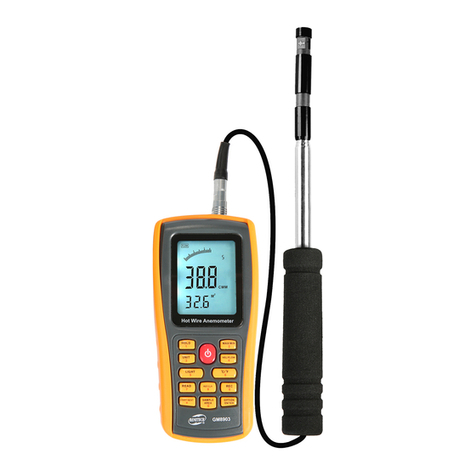
Benetech GM8903 User manual
Benetech
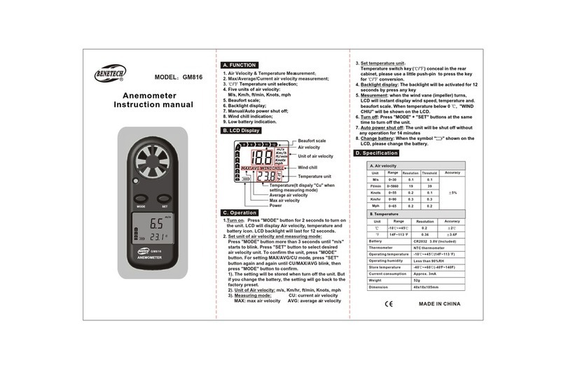
Benetech GM816 User manual
Benetech
Benetech GM1050 User manual

Benetech
Benetech GM816 User manual

Benetech
Benetech GM816 User manual
Benetech
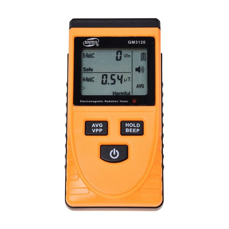
Benetech GM3120 User manual
Popular Measuring Instrument manuals by other brands

Powerfix Profi
Powerfix Profi 278296 Operation and safety notes

Test Equipment Depot
Test Equipment Depot GVT-427B user manual

Fieldpiece
Fieldpiece ACH Operator's manual

FLYSURFER
FLYSURFER VIRON3 user manual

GMW
GMW TG uni 1 operating manual

Downeaster
Downeaster Wind & Weather Medallion Series instruction manual

Hanna Instruments
Hanna Instruments HI96725C instruction manual

Nokeval
Nokeval KMR260 quick guide

HOKUYO AUTOMATIC
HOKUYO AUTOMATIC UBG-05LN instruction manual

Fluke
Fluke 96000 Series Operator's manual

Test Products International
Test Products International SP565 user manual

General Sleep
General Sleep Zmachine Insight+ DT-200 Service manual
