Cosmo LS-R700 User manual

Interface
Installation
Manual
Installation
10
11
1
2
3
4
5
6
7
8
9
Introduction
Interface
Operations
Listed by Purpose
Screen List
Setup
Basic Operations
Troubleshooting
Specifications
Reference
Operation
Manual
Specifications
&
References
Maintenance
Manual
Operation Manual
Installation Manual
Operation Manual
Maintenance Manual
Specifications & References
AIR LEAK TESTER
LS-R700
No.LS-R700-941B1-D


Table of Contents 1
TABLE OF CONTENTS
INSTALLATION MANUAL
1
1Introduction ..................................................................................................................7
1Introduction.........................................................................................................................................8
2Safety Precautions.............................................................................................................................8
3Notes....................................................................................................................................................9
2
2Installation and Setup................................................................................................11
1Unpacking .........................................................................................................................................12
1.1 Accessories ....................................................................................................................................12
1.2 Items to Be Prepared By the Customer.........................................................................................12
2Part Identifications...........................................................................................................................13
2.1 Front Panel.....................................................................................................................................13
2.2 Rear Panel......................................................................................................................................14
2.3 Operation Keys...............................................................................................................................15
3Installation.........................................................................................................................................16
3.1 Environment of Leak Tester and Leak Test Stand .........................................................................16
3.2 Installation of LS-R700 with Quick Mounting Brackets..................................................................16
3.3 Pneumatic Hookups .......................................................................................................................18
3.4 Tubing for Tested part (Work) and Master .....................................................................................20
3.5 Power Source.................................................................................................................................20
3.6 Control I/O Connector ....................................................................................................................21
4Turning on Power for the First Time..............................................................................................22
3
3Interface ......................................................................................................................23
1Control I/O Port.................................................................................................................................24
1.1 Standard Control I/O Port: Phoenix Contact ...............................................................................24
1.2 Control I/O Port D-SUB Connector (Special Spec.) .................................................................25
1.3 Input Specifications ........................................................................................................................26
1.4 Output Specifications......................................................................................................................26
1.5 Typical PLC Connection.................................................................................................................28
1.6 Channel Code.................................................................................................................................29
1.7 Stage Number Output.....................................................................................................................29
1.8 Signal Timing Charts ......................................................................................................................30
1.9 Checking Wiring with I/O Monitor...................................................................................................31
2RS-232C Serial Interface Port.........................................................................................................32
2.1 RS-232C Interface..........................................................................................................................32
2.2 Interface Cable Wiring Example.....................................................................................................32
2.3 Formats of RS-232C Output...........................................................................................................33
2.4 Data Format....................................................................................................................................33
2.5 Checksum.......................................................................................................................................38
2.6 Printer .............................................................................................................................................38
3USB Port............................................................................................................................................40

Table of Contents
2
OPERATION MANUAL
4
4Basic Touch Screen Operations ...............................................................................41
1Turn On Power................................................................................................................................. 42
2Go to Sub Menus and Items........................................................................................................... 42
3Go Back to the Previous Page....................................................................................................... 42
4Switch Pages ................................................................................................................................... 42
5Settings Lock / Unlock.................................................................................................................... 43
5.1 Lock / Unlock Settings................................................................................................................... 43
5.2 Set a Passcode.............................................................................................................................. 44
6Switch the Operation mode between Remote and Manual ........................................................ 44
7Go to Home Screen......................................................................................................................... 44
8Go to Main Menu.............................................................................................................................. 45
9Settings Operations........................................................................................................................ 45
9.1 Change channels........................................................................................................................... 45
9.2 Select an Option From Multiple Selections................................................................................... 45
9.3 Enter a value.................................................................................................................................. 45
5
5Screen List..................................................................................................................47
1Main Menu........................................................................................................................................ 48
2Measurement Screen Menu............................................................................................................ 48
2.1 Measurement Screens (Remote).................................................................................................. 48
2.2 Measurement Screen Description: Standard (Manual).............................................................. 49
2.3 Measurement Screen Description: Advanced (Manual)............................................................. 50
2.4 Measurement Screen Description: Waveform (Manual)............................................................ 50
3Settings Menu.................................................................................................................................. 51
3.1 Basic Settings................................................................................................................................ 51
3.2 Advanced Setting........................................................................................................................... 52
3.3 Common Settings.......................................................................................................................... 54
3.4 Copy Settings ................................................................................................................................ 55
3.5 Initialize to Default......................................................................................................................... 55
3.6 Backup/Restore............................................................................................................................. 55
3.7 CSV Copy to USB.......................................................................................................................... 55
4System Menu ................................................................................................................................... 56
4.1 System Settings............................................................................................................................. 56
4.2 Data to Store in USB ..................................................................................................................... 57
4.3 Test Data Update Time.................................................................................................................. 57
4.4 System Backup/Restore................................................................................................................ 57
5K(Ve) Menu....................................................................................................................................... 58
5.1 K(Ve) Settings................................................................................................................................ 58
5.2 K(Ve) Automatic Setup .................................................................................................................. 59
5.3 K(Ve) Check................................................................................................................................... 59
6Comp. (Compensation) Menu........................................................................................................ 60
6.1 Mastering Settings......................................................................................................................... 60
6.2 Mastering Display.......................................................................................................................... 61
6.3 Drift Comp Settings ....................................................................................................................... 61
6.4 Drift Comp Display......................................................................................................................... 61
6.5 Fixed Comp Settings..................................................................................................................... 61
7Analysis Menu ................................................................................................................................. 62
7.1 Counter .......................................................................................................................................... 62
7.2 X-Chart/List.................................................................................................................................... 62
8Maint. (Maintenance) Menu ............................................................................................................ 62
8.1 Battery Replacement..................................................................................................................... 63

Table of Contents 3
8.2 Error Log.........................................................................................................................................63
8.3 I/O Monitor......................................................................................................................................63
8.4 Inspection .......................................................................................................................................63
8.5 Calibration Reminder......................................................................................................................64
8.6 Inspection Items .............................................................................................................................64
9Language Menu................................................................................................................................64
10 Troubleshooting Menu.....................................................................................................................64
10.1 Error List .........................................................................................................................................65
10.2 Large Leak List...............................................................................................................................65
10.3 Frequent (+) Fails...........................................................................................................................65
10.4 Frequent (-) Fails............................................................................................................................65
11 Misc. (Miscellaneous) Menu............................................................................................................65
11.1 System Version...............................................................................................................................65
6
6Setup ...........................................................................................................................67
1Initial Setups .....................................................................................................................................68
1.1 Operation Mode when the power turns on.....................................................................................68
1.2 Home Screen..................................................................................................................................68
1.3 Set Date..........................................................................................................................................68
1.4 Set Time..........................................................................................................................................68
2Perform a Simple Air Leak Test......................................................................................................69
2.1 Test Parameter Entry......................................................................................................................69
2.2 Timer...............................................................................................................................................69
2.3 Test Pressure..................................................................................................................................69
2.4 Leak Limit .......................................................................................................................................70
2.5 K(Ve)...............................................................................................................................................70
3Flow for Initial Adjustment..............................................................................................................71
4Initial Test Parameter Backup.........................................................................................................73
4.1 System Backup...............................................................................................................................73
5Notation of Air Leak Tests stages and Limits...............................................................................74
6Air Leak Test Result List .................................................................................................................74
7
7Operations Listed By Purposes................................................................................75
1Display Measured Differential Pressure in a Leak Rate Unit......................................................76
1.1 K(Ve) Automatic Setup...................................................................................................................76
1.2 Manual Entry of K(Ve) Value (Leak Coefficient) ............................................................................78
2Reducing Cycle Time.......................................................................................................................78
2.1 Setting Mastering Compensation...................................................................................................78
2.2 Bypass Charge (Option).................................................................................................................80
3Enhance Test Result Reliability......................................................................................................81
3.1 Setting Mastering Compensation...................................................................................................81
3.2 Setting Drift Compensation ............................................................................................................81
3.3 Setting Fixed Compensation..........................................................................................................82
3.4 Use Mastering Comp with Drift Compensation..............................................................................82
3.5 Setting Noise Reduction.................................................................................................................82
3.6 Setting Exhaust Interference Prevention.......................................................................................83
4Enhance Test Reliability..................................................................................................................84
4.1 Setting Idle ΔP Check (Self Check) ...............................................................................................84
5Managing Data on Computer..........................................................................................................84
5.1 Program RS-232C Settings............................................................................................................84
5.2 Collecting Data in USB Memory.....................................................................................................85
5.3 Copy Test Parameters to UBS Memory.........................................................................................87
6Programming Parameters for the Similar Tested Parts...............................................................89
6.1 Copy Settings .................................................................................................................................89
6.2 Initialize to Default..........................................................................................................................89

Table of Contents
4
7Analyze Measured Data .................................................................................................................. 90
7.1 Use X-Chart................................................................................................................................... 90
8Backup and Restore........................................................................................................................ 91
8.1 Restoring Test Parameters............................................................................................................ 91
8.2 Preparing for Replacing LS-R700 ................................................................................................. 92
9Other Settings.................................................................................................................................. 93
9.1 Name Channels............................................................................................................................. 93
10 Other Features................................................................................................................................. 94
10.1 Backlight Auto-off........................................................................................................................... 94
10.2 Select a Language......................................................................................................................... 94
11 For Maintaining Reliable Test Results .......................................................................................... 94
11.1 Daily Inspection Points.................................................................................................................. 94
11.2 K(Ve) Check................................................................................................................................... 95
12 Updating Software........................................................................................................................... 95

Table of Contents 5
MAINTENANCE MANUAL
8
8Maintenance ...............................................................................................................97
1Daily Inspection Points....................................................................................................................98
2Monthly Inspection Points ..............................................................................................................98
3Annual Inspection Points................................................................................................................99
4Features for Maintenance................................................................................................................99
4.1 K(Ve) Check....................................................................................................................................99
4.2 No-Leak Check............................................................................................................................ 100
4.3 DPS Offset Adjustment................................................................................................................ 100
4.4 DPS Span Check......................................................................................................................... 101
4.5 PS Offset Adjustment .................................................................................................................. 101
4.6 PS Span Check............................................................................................................................ 101
5Battery Replacement .................................................................................................................... 102
5.1 Battery Replacement Procedure................................................................................................. 102
5.2 About ERROR 51: Lo Battery SRAM.......................................................................................... 104
5.3 How to Troubleshoot ERROR 51................................................................................................ 105
5.4 If ERROR 51 Occurs Right After Replacing Battery................................................................... 105
6Initializing Memory........................................................................................................................ 105
9
9Troubleshooting.......................................................................................................107
1When an Error Occurred .............................................................................................................. 108
2Error List ........................................................................................................................................ 108
3Error Messages and Treatments ................................................................................................. 109
3.1 ERROR 1 PS Offset Error ........................................................................................................ 109
3.2 ERROR 2 PS Out of Range...................................................................................................... 109
3.3 ERROR 3 Test Pressure Error...................................................................................................110
3.4 ERROR 4 BAL1 Lost Test Pressure..........................................................................................111
3.5 ERROR 10 DPS Offset Error.....................................................................................................111
3.6 ERROR 11 Air Operated Valve Error 1 .....................................................................................112
3.7 ERROR 12 Air Operated Valve Error 2.....................................................................................113
3.8 ERROR 14 Air Operated Valve Error 4.....................................................................................114
3.9 ERROR 15 Air Operated Valve Error 5.....................................................................................115
3.10 ERROR 16 Air Operated Valve Error 6.....................................................................................116
3.11 ERROR 21 DPS Stopped Oscillating........................................................................................117
3.12 ERROR 22 Stop Valves Closed.................................................................................................117
3.13 ERROR 23 Mastering Error.......................................................................................................118
3.14 ERROR 24 K(Ve) Value Out of Range......................................................................................119
3.15 ERROR 25 Leak Limit Out of Range.........................................................................................119
3.16 ERROR 51~ERROR 61 System Errors..................................................................................... 120
4Large Leak List.............................................................................................................................. 121
4.1 Output Signal Timing Charts for Large Leak Timing................................................................... 122
5Frequent (+) Fails.......................................................................................................................... 124
6Frequent (-) Fails........................................................................................................................... 126

Table of Contents
6
SPECIFICATIONS/REFERENCE
1
10
0Specifications...........................................................................................................127
1Primary Specifications.................................................................................................................. 128
2Model Classifications.................................................................................................................... 129
1
11
1Reference..................................................................................................................131
1Leak Testing Overview.................................................................................................................. 132
1.1 Stage Summary........................................................................................................................... 132
1.2 Internal Pressure Changes of the WORK And MASTER ........................................................... 133
1.3 Leak Rate Conversion................................................................................................................. 133
2External Appearance..................................................................................................................... 135
3Pneumatic Circuit.......................................................................................................................... 136
4Pressure Unit Conversion Table.................................................................................................. 138
5Flow Unit Conversion Table......................................................................................................... 138
6Leak Unit Description ................................................................................................................... 138
7CE Marking..................................................................................................................................... 139
8Information to Users (FCC Rules)............................................................................................... 139
9Common Peripherals.................................................................................................................... 140
9.1 External Exhaust Valve (Separately Sold).................................................................................. 140
9.2 Bypass Circuit Unit...................................................................................................................... 140

1 Introduction 7
1
1
1
INTRODUCTION
1Introduction..............................................................................................................8
2Safety Precautions..................................................................................................8
3Notes.........................................................................................................................9
INSTALLATION MANUAL

8 1 Introduction
1
1
1
I
In
nt
tr
ro
od
du
uc
ct
ti
io
on
n
Thank you for purchasing the Air Leak Tester LS-R700 Series.
LS-R700 is a differential pressure decay air leak tester designed for industrial use.
This manual provides installation, operating and maintenance instructions for LS-R700 Series.
Read this operation manual carefully before using this product, and retain it for future reference.
2
2
S
Sa
af
fe
et
ty
y
P
Pr
re
ec
ca
au
ut
ti
io
on
ns
s
This section provides how to use the product safely and avoid injuries to the operators or damages to your assets. Please
handle the product according to these instructions and observe the following symbols that appear in this manual:
[Explanations of the signs]
Symbol Explanation
Failure to take or avoid a specific action could result in death or serious physical harm to the
user.
Failure to take or avoid a specific action could result in minor physical harm to the user, or in
property damage.
[Explanations of the symbols]
ΔThis symbol denotes a warning/caution to alert the users. Aspecific explanation of the potential danger and what must be
done to avoid it follows. (Example: Electrical shock hazard)
1) Ground the product before plugging it into a power
source. Neglecting it could result in electrical shock
hazards. Do not ground the product to a gas pipe. It
could result in fires or electrical shock hazards.
2) If the metal part of the power plug or surrounding area
is dusty, clean it thoroughly with a dry cloth.
Neglecting it could result in fires or electrical shock
hazards.
3) Do not use voltages other than those for which the
product is rated. It could result in fires or electrical
shock hazards.
4) If the product has been dropped or damaged, switch it
off and disconnect the power plug from the outlet.
Neglecting it could result in fires or electrical shock
hazards.
5) Do not apply air pressure in excess of the pressure
rating of the product. Excessive pressure input could
cause major component failure and/or injury.
6) Should foreign matter such as water or oil get inside
the product, switch off the power immediately and
unplug it from the outlet. Neglecting it could result in
fires or electrical shock hazards. Use extra caution
when installing the product in an environment where
water or oil exists nearby.
7) This product is not customer-serviceable. Customer
servicing could result in fires or electrical shock
hazards.
8) Replace a fuse after turning off the power of the main
unit and disconnecting the power plug from the outlet.
Use a fuse equivalent to the current one for
replacement. Using a different fuse could result in
fires or electrical shock hazards.
9) Discontinue using the product immediately under the
following circumstances:
• The product smokes.
• The product emits abnormal noises.
• The product has developed problems not
covered in the Operation Manual.
• The product cannot be operated as indicated
in the Operation Manual.
To avoid electrical shock hazards or physical
harm, disconnect the power cable and remove
the pressure source from the instrument. Not
doing so could result in fires or electrical shock
hazards.
WARNING
CAUTION
WARNING

1 Introduction 9
1
1) Do not use the product in places that are damp, that
are exposed to direct sunlight or that are outside the
temperature range of 5°C to 40°C. Using the product
in such environments could result in malfunctions or
failures.
2) To avoid damage to the power cable, which could
result in fires or electrical shock hazards, observe
these precautions:
• Do not damage, modify or apply undue force
to the power cable.
• Before servicing the product, disconnect the
power plug from the outlet.
• Do not handle the power plug with wet hands.
• When disconnecting the power plug, do not
pull on the power cable.
3) Mount the product securely on a structure with enough
load capacity. Do not install the product on the
insecure foundation or in places with vibration to avoid
overturns and injuries.
4) Ensure the correct cable connection. Incorrectly
connected cables could result in damage to the
product and surrounding hardware.
5) Do not step on top of the product or place containers
filled with liquids, oil or soapy water, or the like on it.
Spills may result, causing physical harm, electrical
shock hazard, rust or other damage.
6) Should the LCD become damaged, avoid skin contact
with the liquid contained inside. It could cause
inflammation. Wash with running water in case of
skin contact.
7) Do not disassemble the product other than replacing
the designated consumable parts. The product could
malfunction, resulting in physical harm or electrical
shock hazards..
8) Do not install or remove the tubing with the product
connected to an air pressure source. It could result in
physical harm.
Wear a safety goggle to protect your eyes.
9) When a leak test has been completed, unclamp the
tested part only after all pressure has been released
from the product. Residual pressure could result in
physical harm.
10) Hold its bottom to keep it from dropping when
transferring the product. Do not lift the product by
gripping its components on the rear panel such as the
stop valves.
11) Put on steel-toe boots when transferring the product
for shipping, installation, dismantling. Neglecting it
could result in physical harm by dropping the product..
12) Wipe out the product lightly with a dry and soft cloth for
maintenance. When the product is with heavy dirt,
dilute the neutral detergent with water, soak the cloth in
the detergent, squeeze the cloth, and wipe the dirt out.
Do not use organic solvent.
13) Handle the product according to the instructions in this
operation manual or the protection feature equipped
with the product will be compromised.
3
3
N
No
ot
te
es
s
1) The information in this document is subject to change without notice to allow for performance or feature upgrades.
2) This document may not be reproduced in whole or in part without prior approval of the publisher.
3) We are not responsible for the items tested using the product or for any consequences resulting from the tests.
4) This product comes with the self-check feature to detect certain improper settings and/or operations, and any
malfunctions of components to minimize incorrect pass/fail judgment. However the scope of monitoring by
self-checking, however, is limited.
5) This product is a differential pressure decay air leak tester adopting the master comparison method. Please note that
when using the product in an inappropriate environment, there are risks of incorrect fail judgments due to various effect
such as leakage from the sealing fixture, part deformation, temperature changes in the part and/or fixture.
6) The user is encouraged to consult your local Cosmo representative directly for any questions regarding the use of this
product.
CAUTION


2 Installation and Setup 11
2
2
2
INSTALLATION AND SETUP
1Unpacking ..............................................................................................................12
1.1 Accessories.................................................................................................................12
1.2 Items to Be Prepared By the Customer.......................................................................12
2Part Identifications................................................................................................13
2.1 Front Panel..................................................................................................................13
2.2 Rear Panel...................................................................................................................14
2.3 Operation Keys............................................................................................................15
3Installation..............................................................................................................16
3.1 Environment of Leak Tester and Leak Test Stand........................................................16
3.2 Installation of LS-R700 with Quick Mounting Brackets ................................................16
3.3 Pneumatic Hookups.....................................................................................................18
3.4 Tubing for Tested part (Work) and Master ...................................................................20
3.5 Power Source..............................................................................................................20
3.6 Control I/O Connector..................................................................................................21
4Turning on Power for the First Time....................................................................22

12 2 Installation and Setup
2
1
1
U
Un
np
pa
ac
ck
ki
in
ng
g
When you receive the LS-R700, unpack and check for the transport damage.
1.1 Accessories
Power cord 1
Control I/O connector: MSTB 2,5 / 16-STF-5,08 (Phoenix Contact) 2
Inspection record / Traceability related documents 1 each
Operation manual CD
(Installation manual / Operation manual / Maintenance manual / Specifications & References) 1
1.2 Items to Be Prepared By the Customer
For installation:
For mounting LS-R700 with Quick mounting bracket: M4 screws (4)
Tube for pneumatic connection
Tube for connecting the tested part and reference master to LS-R700
For external device connection:
Control I/O cable
DCV24 Power source
For storing leak test data and/or test parameters:
USB memory
Computer
RS-232C serial communication cable
2 Installation and Setup 13
2
2
2
P
Pa
ar
rt
t
I
Id
de
en
nt
ti
if
fi
ic
ca
at
ti
io
on
ns
s
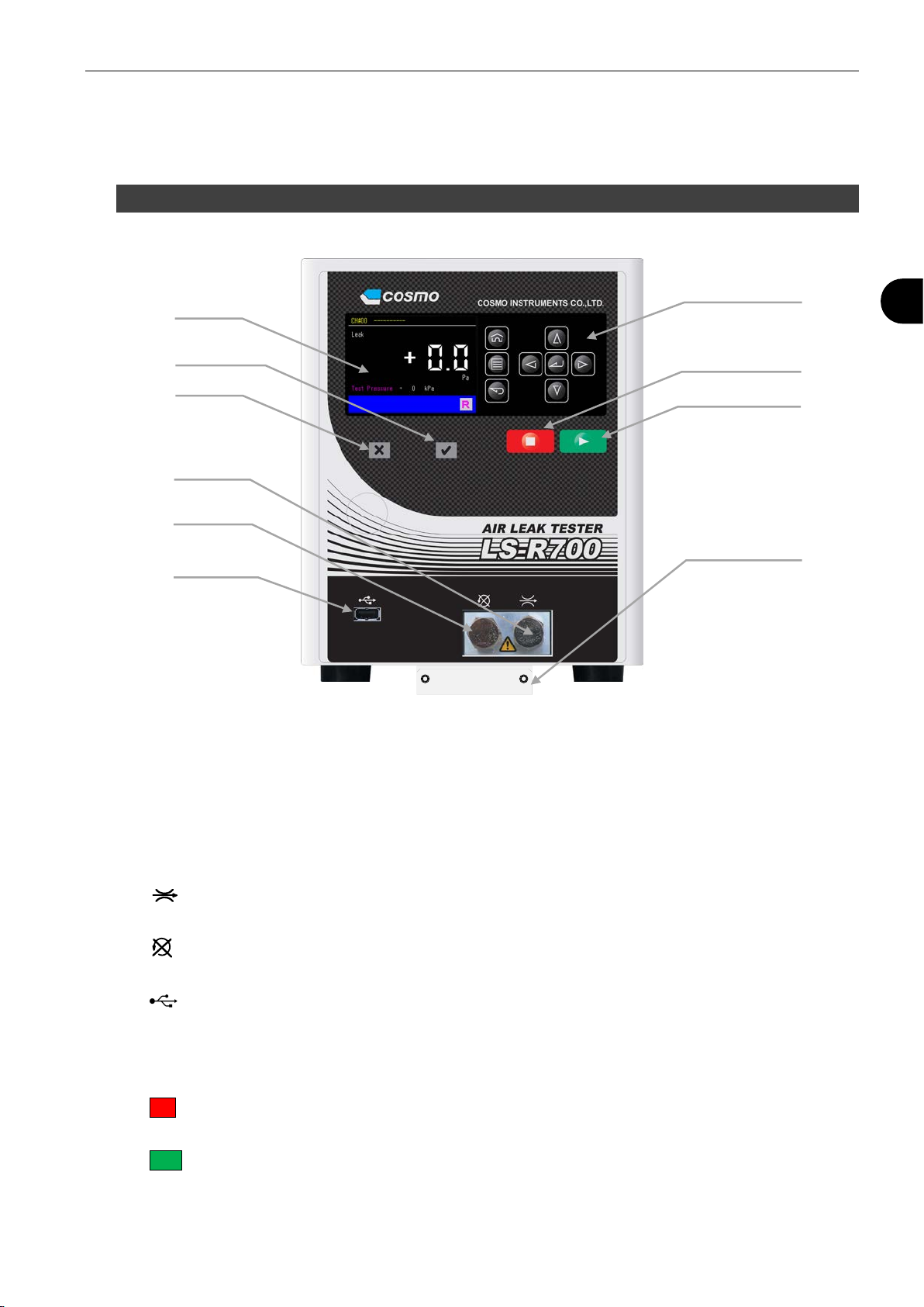
2.1 Front Panel
A Color LCD:
B Pass lamp:
Lights when the test result is “Pass”.
C Fail lamp:
Lights when the test result is “Fail”.
D (Calibration port):
Connect a Leak Master to this port for daily maintenance.
E (Maintenance port):
Do not remove the plug when
F (USB port):
Test Data, Waveform Data and Mastering Data are output in CVS format.
Software can be upgraded using this port.
G Operation keys
H ■key:
Used to stop a measurement in manual mode.
I ►key:
Used to start a measurement in manual mode.
J Quick Mounting Bracket:
Using this bracket, LS-R700 can be installed and removed easily with two M4 screws.
B
D
H
G
A
C
E
F
J
I
14 2 Installation and Setup
2
2.2 Rear Panel
A CONTROL I/O (Phoenix contact):
External device is connected to control
LS-R700 externally.
Upper: Input ALower: Output B
B CONTROL I/O (Special specification):
D-sub connector
C COM 1:
Serial communication port.
Data is output in the designated format.
(RS-232C 9-pin male)
D G3:
Pilot pressure port for External Exhaust valve
(Push-to-connect fitting 4mm)
E PILOT PRESSURE:
Pilot pressure port
Connect clean air regulated from 400 to 700
kPa
F MASTER:
MASTER-side stop valve.
A port to connect a reference (Master).
Leave the valve opened except for
maintenance.
G EXHAUST:
Silencer for exhaust
Air is exhausted from this port after a leak test.
H WORK:
WORK-side stop valve
A port to connect a tested part (Work).
Leave the valve opened except for
maintenance.
I POWER: Power switch
J FUSE: Fuse (T2.5A 250V)
K 100 - 240 VAC~:Power inlet
L FG: Grounding
M TEST PRESSURE:
Test pressure port
(Push-to-connect fitting 4mm)
N BYPASS FILL (Option):
Pilot pressure port for fill valve for Bypass
circuit unit
O Stop Valve Monitoring Switch with a valve
cover (Option):
When the valve(s) is open, the cover won’t
close and the switch is not pressed.
This is to prevent leak testing with the stop
valves closed.
P EP REGULATOR (Option):
Electro-Pneumatic regulator connector
WORK
COSMO INSTURUMENTS CO., LTD
MADE IN JAPAN
MASTEREXHAUST
G3
T2.5A–250V
100-240VAC~50/60Hz
100VA MAX.1ph
POWER
COM1
BYPASS
FILL
A
B
C
D
E
F
G
H
I
J
K
L
M
N
O
P

2 Installation 15
2
2.3 Operation Keys
A Home key:Used to open a measurement screen programmed to be the Home screen.
B Menu key:Used to open the main menu
C Back key:Used to back to the previous screen.
D Enter key:Used to complete the selection or numeric entry.
E Cursor keys: Used to move the cursor within a page or program numbers.
A
B
C
D
E
16 2 Installation
2
3
3
I
In
ns
st
ta
al
ll
la
at
ti
io
on
n
3.1 Environment of Leak Tester and Leak Test Stand
Location of Leak Tester to Avoid Temperature Fluctuation
• Avoid direct sunlight.
• Avoid direct wind due to doors opening and closing.
• Avoid direct wind from heating and cooling vents.
When above cannot be avoided, use a curtain. However, it’s not good to cover the whole test stand area
completely because of temperature fluctuations that could occur in the tested parts. Therefore, partial
covering will give better result.
Effects of Plant Temperature on Leak Testing
• Do not put the leak test station right after heating, cooling welding or washing processes.
• If the temperature of the floor and test bench are different, and the tested parts are taken from the floor,
heat transfer will take place between the parts and the fixture. This will cause an error. The tested
parts should be stored at the same level as the test bench in order to keep the temperature the same.
3.2 Installation of LS-R700 with Quick Mounting Brackets
LS-R700 comes with a mounting bracket that can be install/remove from the base with two screws.
Mounting Base
This base is loosely attached to the bottom of LS-R700. Remove it from the tester and mount it on the leak
test stand where LS-R700 is to be mounted with four M4 screws. The mounting surface has to be flat and
smooth.
Mount the mounting base on the test bench as shown below. M4 screws are not enclosed with LS-R700.
Hold its bottom to keep it from dropping when
transferring the product. Do not lift the product by
gripping its components on the rear panel such as
the stop valves.
CAUTION
Mount the product securely on a structure with enough
load capacity. Do not install the product on the insecure
foundation or in places with vibration to avoid overturns
and injuries.
CAUTION
Mounting Base
Top of LS-R700
50
70
17.8 275
195
Φ4.5 mounting holes (4)
Front
side Rear
side

2 Installation 17
2
How to Mount
Two mounting brackets are attached to the bottom of the LS-R700, A in front and B in back.
Mount as the following procedure:
Place the LS-R700 with the
Brackets Aand Battached a
little toward the front of where
the LS-R700 is to be
mounted.
Insert the bracket B to the rear
latch of the mounting base
while lifting the front of the
LS-R700.
Lower the LS-R700 where the
Bracket A gets behind the
front latch of the mounting
base and align the screw
holes.
Mount the LS-R700 with two
M4 screws.
Mount the “Mounting Base” on
a leak test stand.
Mounting Bracket A Mounting Bracket B
Mounting Base
18 2 Installation
2
3.3 Pneumatic Hookups
Standard Connection Example
Optional Equipment Connection
WORK
COSMO INSTURUMENTS CO., LTD
MADE IN JAPAN
MASTEREXHAUST
G3
T2.5A–250V
100-240VAC~50/60Hz
100VA MAX.1ph
POWER
COM1
BYPASS
FILL
Tested Part
Test Pressure
Air Dryer
Drain
Pilot pressure
Regulated between 400 and 700kPa.
Master Chamber
(Sold Separately)
Be sure to shut off the pressure source
before connection/disconnection.
CAUTION
WORK
COSMO INSTURUMENTS CO., LTD
MADE IN JAPAN
MASTEREXHAUST
G3
T2.5A–250V
100-240VAC~50/60Hz
100VA MAX.1ph
POWER
COM1
BYPASS
FILL
Air Dryer
Test Pressure
Drain
Bypass Circuit Unit
Pilot pressure
Regulated between 400 and 700kPa.
Tested Part External Exhaust Vavle
G3-ME
Master Chamber
(Sold Separately)
Table of contents
Other Cosmo Test Equipment manuals


