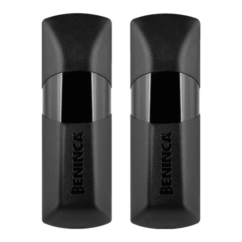
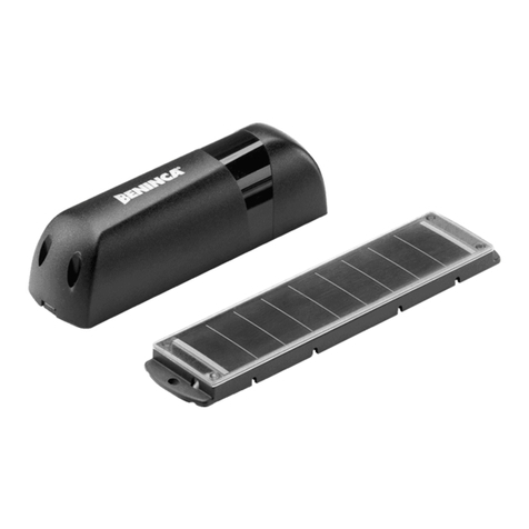
Beninca RF.SUN User manual

L8542946
02/2013 rev 2
RF/RF.SUN
UNIONE NAZIONALE COSTRUTTORI
AUTOMATISMI PER CANCELLI, PORTE
SERRANDE ED AFFINI


1
2
3
1
2
3
2
3
41

3
4
B
B
D
F
F
A
I
C
E
D
E
4
1
NOT
USED
2 3
(-)
4
(+)
J2 DAS
Open
DAS N.C.
J2 DAS
Close
DAS 8K2
S1
J1
LED 2
J2
RF.+ SUN PANEL
J1 Close
RF
J1 Open

Dichiarazione CE di conformità
Fabbricante: Automatismi Benincà SpA.
Indirizzo: Via Capitello, 45 - 36066 Sandrigo (VI) - Italia
Dichiara che: Il radiotrasmettitore/radioricevitore per bordi sensibili mobili RF-RF.SUN-SC.RF.
è conforme alle seguenti disposizioni pertinenti:
Direttiva sulla compatibilità elettromagnetica: 89/336/CCE, 93/68/CEE
Direttiva sulla bassa tensione: 73/23/CEE, 93/68/CEE
ETSI EN 301 489-3 V1.4.1 (2002)
ETSI EN 301 489-1 V1.4.1 (2002)
ETSI EN 300 220-3 V1.1.1 (2000)
EN12978
EN 954-1 CAT2
EN 12453
Benincà Luigi, Responsabile legale.
Sandrigo, 07/07/2011.
DATI TECNICI
DISPOSITIVO PER BORDI MOBILI RF
Alimentazione 2 batterie 1.5 V alcaline 2.7 Ah
Portata massima in condizioni ottimali 100 m
Grado di protezione IP 55
Temp. di funzionamento -20°C/+70°C
Durata batterie 3 anni con 10 aperture/giorno
Frequenza di funzionamento 868 MHz
Tempo di risposta 500 ms
DISPOSITIVO PER BORDI MOBILI RF.SUN
Alimentazione 2 batterie 1.2 V NiMh (1800mAh) AA ricaricabili
Portata massima in condizioni ottimali 100 m
Grado di protezione IP 55
Temp. di funzionamento -20°C/+70°C
Durata batterie (in assenza di carica) 150 giorni
Frequenza di funzionamento 868 MHz
Tempo di risposta 500 ms
PANNELLO SOLARE SUN
Cella solare silicio amorfo
Dimensioni 43x185x12mm
Corrente di ricarica
30 mA con 50000 Lux (sole)
10 mA con 20000 Lux (variabile)
0,5 mA con 2000 (coperto)
Tensione di ricarica 4,5V
Tempo di carica 96h
5

6
RF / RF.SUN
DESCRIZIONE
Radiotrasmettitore per bordi sensibili per applicazione su ante mobili conforme alla normativa EN 12978.
Consente la comunicazione bidirezionale via radio tra il dispositivo sul bordo mobile e il ricevitore SC.RF
installato a bordo della centrale di comando.
E’ disponibile in 2 versioni (Fig.1):
1 RF*: Alimentato con due batterie tipo AA alcaline.
2 RF.SUN: Alimentato da due batterie NIMH ricaricate per mezzo del pannello solare SUN (Fig.1-rif.3) da
installare sull’anta mobile.
In entrambi i modelli è possibile utilizzare sia bordi sensibili di tipo resistivo (8K2) sia bordi di tipo meccanico
con contatto normalmente chiuso.
FUNZIONAMENTO
In figura 2 è rappresentata una tipica installazione del trasmettitore RF.SUN sull’anta di un motore scorre-
vole.
1 Trasmettitore RF o RF.SUN, invia a mezzo radio al ricevitore SC.RF lo stato del bordo sensibile.
2 Bordo sensibile resistivo o meccanico.
3 Pannello solare SUN, provvede alla ricarica della batteria interna all’RF.SUN
4 Ricevitore radio SC.RF, replica lo stato del bordo sensibile alla centrale di comando.
Note: SC.RF dispone di due distinti canali di comunicazione, ognuno dei quali può memorizzare fino a 4
dispositivi RF/RF.SUN, è pertanto possibile installare fino ad un massimo di otto bordi sensibili.
Ogni trasmettitore richiede una procedura di apprendimento per la comunicazione con il ricevitore, utiliz-
zando il pulsante S1 (Fig.3) come indicato nel manuale fornito con SC.RF.
COLLEGAMENTI (Fig.3)
1-2 Ingresso contatto bordo sensibile.
3-4 Ingresso alimentazione da pannello solare.
3- nero (bianco)
4+ rosso (marrone).
J1 Ponticello di selezione alimentazione.
Ponticello aperto: il dispositivo è alimentato solo dalla batteria interna
Ponticello chiuso: il dispositivo è alimentato dalla batteria interna, la cui ricarica è affidata al pannello
SUN.
J2 Ponticello di selezione bordo sensibile.
Ponticello aperto: bordo meccanico
Ponticello chiuso: bordo resistivo 8K2
FISSAGGIO (Fig.4)
A Fondo
B Viti fissaggio a parete
C Circuito stampato
D Viti fissaggio
E Predisposizione passaggio cavi
F Viti chiusura
I Vano per due batterie AA 1.5V
SOSTITUZIONE BATTERIA
Le batterie alcaline in dotazione con il dispositivo RF, dopo un certo periodo, più o meno prolungato a se-
conda delle condizioni di utilizzo, richiedono la sostituzione.
Possono essere sostituite da normali batterie alcaline formato AA.
Le batterie NiMh in dotazione con SUN.RF, hanno una durata molto maggiore, la loro sostituzione avviene
solo al termine della capacità di ricarica, e devono essere esclusivamente con batterie analoghe.
Tutte le batterie sono rifiuti speciali!
Non disperderle nell’ambiente ma smaltirle secondo le normative vigenti

7
LED DI SEGNALAZIONE
Il LED 2 evidenziato in Figura 3 svolge la funzione di diagnostica del dispositivo.
Premere brevemente il tasto S1:
- se il led inizia a lampeggiare, significa che il bordo sensibile non rileva ostacoli
- se il led si accende con luce fissa, significa che è stato rilevato un ostacolo. Il trasmettitore sta inviando il
segnale di allarme al ricevitore.
AVVERTENZE IMPORTANTI
Per il corretto funzionamento è importante osservare scrupolosamente quante segue:
1 Il pannello solare deve essere installato in una posizione ben esposta ai raggi solari, con il pannello tra-
sparente rivolto verso l’alto.
2 Verificate che nel corso della giornata il pannello non cada in una zona ombreggiata (alberi, edifici, ecc).
3 Mantenere periodicamente pulito il pannello solare da polvere e sporcizia.
4 Migliore sarà l’esposizione del pannello, migliori saranno le prestazioni e l’affidabilità del dispositivo.
Nel caso di installazione in luoghi scarsamente soleggiati, è possibile collegare 2 pannelli solari in
parallelo.
5 Il sistema correttamente installato e mantenuto in perfetta efficienza è in grado di funzionare per un pe-
riodo molto prolungato, al termine del quale sarà comunque necessario sostituire la batteria, a causa del
raggiungimento del numero massimo di cicli di ricarica.
6 Il dispositivo correttamente installato e manutenzionato consente il rispetto del grado di sicurezza previsto
dalle normative vigenti. Tuttavia il produttore declina ogni responsabilità per qualsiasi danno provocato a
persone o cose causati da errata installazione, errata manutenzione, utilizzo improprio o non corretto del
dispositivo.
AVVERTENZE
L’installazione dei dispositivi di sicurezza e la loro verifica funzionale deve essere effettuata esclusivemente
da personale qualificato nel rispetto delle normative vigenti.
I dispositivi di sicurezza devono essere fatti conoscere a tutte le persone appropriate. Le aree che danno
accesso ai dispositivi devono essere tenute libere da ostacoli.
Qualsiasi modifica ai collegamenti e alla configurazione dell’impianto deve essere effettuata esclusivamente
da personale qualificato, autorizzato dal costruttore.
In caso di arresto di emergenza il sistema, una volta rimosso l’ostacolo, si autoripristina. In caso di mancato
ripristino verificare il corretto cablaggio della SC.RF e lo stato di carica della batteria del dispotivo mobile.
Utilizzare esclusivamente parti di ricambio originali, fornite dal costruttore.
Al termine dell’installazione le marcature che contraddistinguono il prodotto devono rimanere visibili.
MANUTENZIONE
I dispositivi di sicurezza devono essere mantenuti in condizioni di lavoro efficienti e mantenuti in accordo
con le istruzioni del fabbricante.
Periodicamente controllare:
- le batterie dei dispositivi mobili, nel caso procedere con la loro sotituzione.
- la pulizia del pannello solare eventualmente pulire con un panno leggermente inumidito, non utlizzare
solventi per la pulizia.
SMALTIMENTO
Qualora il prodotto venga posto fuori servizio, è necessario seguire le disposizioni legislative in vigore al
momento per quanto riguarda lo smaltimento differenziato ed il riciclaggio dei vari componenti (metalli,
plastiche, cavi elettrici, ecc.); è consigliabile contattare il vostro installatore o una ditta specializzata ed
abilitata allo scopo.

EC Declaration of Compliance
Manufacturer: Automatismi Benincà SpA.
Address: Via Capitello, 45 - 36066 Sandrigo (VI) - Italy
This is to certify that:
The radio-transmitter/radio-receiver for movable sensitive safety edges RF-RF.SUN-SC.RF.
is compliant with the following regulations:
Directive on the electromagnetic compatibility: 89/336/CCE, 93/68/CEE
Directive on low voltage:73/23/CEE, 93/68/CEE
ETSI EN 301 489-3 V1.4.1 (2002)
ETSI EN 301 489-1 V1.4.1 (2002)
ETSI EN 300 220-3 V1.1.1 (2000)
EN12978
EN 954-1 CAT2
EN 12453
Benincà Luigi, Legal Officer.
Sandrigo, 07/07/2011.
TECHNICAL DATA
DEVICE FOR RF MOBILE SAFETY EDGES
Power supply 2 batteries, 1.5V, alkaline 2.7Ah
Max range in optimal conditions 100 m
Protection level IP 55
Operating temperature -20 °C / +70° C
Duration of batteries 3 years with 10 openings/day
Operating frequency 868 MHz
DEVICE FOR RF MOBILE SAFETY EDGES
Power supply
2 batteries 1.2 NiMh (1800mAh), AA rechargeable
Max range in optimal conditions 100 m
Protection level IP 55
Operating temperature -20°C / +70°C
Duration of batteries (without load) 150 days
Operating frequency 868 MHz
SUN SOLAR PANEL
Solar cell Amorphous silicon
Overall dimensions 43x185x12mm
Recharge current
30 mA with 50000 Lux (sun)
10 mA with 20000 Lux (changeable)
0,5 mA with 2000 (clwdy)
Recharge voltage 4.5V
Charge time 96h
8

9
RF / RF.SUN
DESCRIPTION
Radio-transmitter for sensitive safety edges, to be applied on movable closures, pursuant to EN
12978 standard.
This allows for the bi-directional communication via radio between the device on mobile edge
and the SC.RF receiver mounted on the control unit.
It is available in 2 versions (Fig. 1):
1 RF*: Powered with two alkaline batteries, AA type.
2 RF.SUN: It is powered with two NiMh batteries, recharged by solar panel SUN (Fig. 1 – ref. 3)
to be installed on the movable closure.
Both sensitive edges of the resistive type (8K2) and edges of the mechanical type can be used
on both models with normally closed contact.
OPERATION
A typical installation of the RF.SUN transmitter on the leaf of a sliding motor is shown in figure
2.
1 RF or RF SUN transmitter. The status of the sensitive edge is sent via radio to the SC.RF
receiver.
2 Sensitive safety edge of the resistive or mechanical type.
3 The SUN solar panel provides for the recharging of the battery inside the RF.SUN device
4 The SC.RF radio receiver sends information on the status of the sensitive edge to the control
unit.
Note: SC.RF is provided with two separate communication channels, each of them is able to sto-
re up to 4 RF/RF.SUN devices. Therefore, up to eight sensitive safety edges can be mounted.
Each single transmitter requires a special learning proceeding to communicate with the recei-
ver, by using the push-button S1 (Fig. 3), as indicated in the manual supplied with SC.RF.
WIRE CONNECTIONS (Fig. 3)
1-2 Input, sensitive safety edge.
3-4 Input, power supply from solar panel.
3- black (white).
4+ red (brown).
J1 Selection jumper, power supply.
Open jumper: The device is powered by inside battery only
Closed jumper: The device is powered by inside battery which is recharged through SUN
panel.
J2 Jumper to select the sensitive safety edge. Open jumper: safety edge of the mechanical
type
Closed jumper: safety edge of the resistive type, 8K2
FITTING (Fig. 4)
A Bottom
B Screws for fitting to wall
C Printed board
D Fitting screws
E Presetting for the passage of cables
F Closing screws
I Niche for two batteries, AA 1.5V
REPLACEMENT OF THE BATTERY
After a certain period, more or less long according to conditions of use, alkaline batteries sup-
plied with the RF device should be replaced.
They can be replaced by standard AA alkaline batteries.

10
The NiMh batteries supplied with SUN.RF feature a much longer duration. They need to be re-
placed only when their rechargeable capacity is ended and must be mandatorily replaced with
similar batteries.
All batteries are considered as special waste!
Do not leave in the environment but dispose the batteries according to regulations in
force.
INDICATOR LED
LED 2, shown in Figure 3, performs the diagnostics function of the device.
Press key S1 for a short period of time:
- if the LED starts flashing, this means that the sensitive safety edge has not hit any obstacle
- if the LED switches on with fixed light, this means that an obstacle has been detected. The
transmitter is sending an alarm signal to the receiver.
IMPORTANT NOTICE
For the correct operation of the device, the following should be carefully followed:
1 The solar panel must be mounted where it will get direct sun exposure. The transparent panel
must be turned upwards.
2 Check that during the day the panel is not shaded (trees, buildings, etc.).
3 Clean the solar panel periodically from dust and dirt.
4 The better the exposure of the panel, the better the performance and reliability of the device.
If the panel is mounted in areas with little sun exposure, 2 solar panels can be connected
in parallel.
5 If correctly installed and maintained perfectly efficient, the system will be able to operate for a
very long period of time. At the end of this period, the battery should be however replaced due
to the maximum number of recharge cycle reached.
6 A correctly installed and maintained device will comply with the safety level set out be regu-
lations in force. However, the manufacturer shall be held harmless for any damages or injuries
caused by incorrect installation, incorrect maintenance, unintended or incorrect use of the de-
vice.
DISPOSAL
When the product is out of order, it must be disposed according to regulations in force on waste
disposal and recycling of the various components (metal, plastics, electrical wires, etc.). For this
purpose, it is advisable to contact your installer or a specialised company.

11
EG-Konformitätserklärung
Der Hersteller: Automatismi Benincà SpA.
Adresse: Via Capitello, 45 - 36066 Sandrigo (VI) - Italien
erklärt dass: das Sendegerät/der Empfänger für mobile empfindliche Schaltleisten
RF-RF.SUN-SC.RF.
den nachfolgenden Vorschriften entspricht:
Richtlinie über die elektromagnetische Verträglichkeit: 89/336/CCE, 93/68/CEE
Richtlinie über Niederspannung: 73/23/CEE, 93/68/CEE
ETSI EN 301 489-3 V1.4.1 (2002)
ETSI EN 301 489-1 V1.4.1 (2002)
ETSI EN 300 220-3 V1.1.1 (2000)
EN12978
EN 954-1 CAT2
EN 12453
Benincà Luigi, Rechtsvertreter
Sandrigo, 07/07/2011.
TECHNISCHE DATEN
VORRICHTUNG FÜR MOBILE EMPFINDLICHE SCHALTLEISTEN RF
Speisung 2 Alkali-Batterien 1,5V – 2,7 Ah
Maximale Tragweite unter optimalen Bedingungen 100 m
Schutzklasse IP 55
Betriebstemperatur -20°C/+70°C
Lebensdauer der Batterien 3 bei 10 Öffnungen/Tag
Betriebsfrequenz 868 MHz
VORRICHTUNG FÜR MOBILE EMPFINDLICHE SCHALTLEISTEN RF.SUN
Speisung 2 NiMh-Batterien 1,2V (1800mAh) AA aufladbar
Maximale Tragweite unter optimalen Bedingungen 100 m
Schutzklasse IP 55
Betriebstemperatur -20°C/+70°C
Lebensdauer der Batterien (ohne Aufladung) 150 Tage
Betriebsfrequenz 868 MHz
SOLARZELLENPANEEL SUN
Solarzelle glasiges Silizium
Maße 43x185x12mm
Ladestrom
30 mA bei 50000 Lux (Sonne)
10 mA bei 20000 Lux (wolkig)
0,5 mA bei 2000 Lux (bewölkt)
Ladespannung 4,5V
Ladezeit 96h

12
RF / RF.SUN
BESCHREIBUNG
Sendegerät für empfindliche Schaltleisten für mobile Torflügel. Entspricht der Norm EN 12978.
Gestattet die Kommunikation in beide Richtungen über Funk zwischen Vorrichtung an der mo-
bilen Schaltleiste und Empfänger SC.RF, der an Bord der Steuerzentrale installiert ist.
Das Sendegerät ist in zwei Ausführungen erhältlich (Abb. 1):
1 RF*: über zwei Alkali-Batterien des Typs AA gespeist.
2 RF.SUN: über zwei NiMh-Batterien gespeist, die über ein Solarpaneel SUN aufgeladen wer-
den (Abb. 1, Ref. 3), das an der mobilen Schaltleiste installiert wird.
Beide Modelle können sowohl an den widerstandsfähigen Schaltleisten (8K2) als auch an den
mechanischen Schaltleisten mit Ruhekontakt verwendet werden.
BETRIEB
Die Abbildung 2 zeigt eine typische Installation des Sendegeräts RF.SUN an einem motorge-
steuerten Schiebetor.
1 Sendegerät RF oder RF.SUN. Dieses sendet dem Empfänger SC.RF per Funk, den Status
der empfindlichen Schaltleiste.
2 Widerstandsfähige oder mechanische Schaltleiste
3 Solarzellenpaneel SUN, zum Aufladen der Batterie im Inneren des RF.SUN.
4 Funkempfänger SC:RF, wiederholt den Status der empfindlichen Schaltleiste für die Steue-
reinheit.
Bemerkungen: SC.RF verfügt über zwei unterschiedliche Kommunikationskanäle. Jeder Kanal
kann bis zu 4 Vorrichtungen RF/RF.SUN speichern, was die Installation von bis zu maximal acht
empfindlichen Schaltleisten ermöglicht.
An jedem Sendegerät muss die Prozedur der Selbstlernfunktion für die Kommunikation mit dem
Empfänger über die Taste S1 (Abb. 3), laut Anweisungen des mit dem SC.RF mitgelieferten
Handbuchs vorgenommen werden.
ANSCHLÜSSE (Abb.3)
1-2 Eingang Kontakt Sicherheitsleiste.
3-4 Eingang Speisung des Solarpaneels
3- schwarz (weiß)
4+ rot (braun)
J1 Brücke zur Wahl der Stromversorgung.
Geöffnete Brücke: die Vorrichtung wird nur über eine interne Batterie gespeist
Geschlossene Brücke: die Vorrichtung wird über die interne Batterie gespeist, die über
das Solarpaneel SUN aufgeladen wird.
J2 Brücke zur Wahl der Sicherheitsleiste. Geöffnete Brücke: mechanische Leiste
Geschlossene Brücke: wiederstandsfähige Leiste 8K2
BEFESTIGUNG (Abb. 4)
A Boden
B Wandbefestigungsschrauben
C Platine
D Befestigungsschrauben
E Kabeldurchführung
F Verschlussschrauben
I Batteriefach für zwei Batterien AA 1,5 V
BATTERIE AUSWECHSELN
Die mit der Vorrichtung RF mitgelieferten Batterien müssen nach einer bestimmten Zeit (je nach
Gebrauch und Gebrauchsbedingungen) ersetzt werden.
Sie können durch normale Alkali-Batterien des Typs AA ersetzt werden.

13
Die NiMh-Batterien, die mit dem SUN.RF geliefert werden, haben eine viel längere Lebensdau-
er. Sie müssen erst ersetzt werden, wenn sie nicht mehr aufladefähig sind. Sie dürfen aus-
schließlich mit Batterien desselben Typs ersetzt werden.
Alle Batterien müssen als Sondermüll entsorgt werden!
Nicht ins Freie werfen, sondern laut den geltenden Vorschriften entsorgen.
LED UND MELDESIGNAL
Die in der Abbildung 3 aufgeführte LED 2 entspricht der Diagnostik-Funktion der Vorrichtung.
Die Taste S1 kurz drücken:
- Wenn die Leuchte blinkt, bedeutet das, dass die empfindliche Schaltleiste keine Hindernisse
erkannt hat
- Wenn die Led fest leuchtet, bedeutet das, dass ein Hindernis erkannt worden ist. Das Sende-
gerät sendet ein Alarmsignal an den Empfänger.
WICHTIGE HINWEISE
Für einen einwandfreien Betrieb sind folgende Bedingungen wichtig:
1 Das Solarpaneel muss an einem sonnigen Ort installiert werden, wo es der Sonne ausgesetzt
und mit der durchsichtigen Fläche nach oben gerichtet ist.
2 Kontrollieren, ob im Laufe des Tages das Paneel im Schatten liegt (Bäume, Gebäude usw.).
3 Das Solarpaneel regelmäßig reinigen und Schmutz und Staub entfernen.
4 Umso besser das Paneel der Sonne ausgesetzt ist, umso besser sind die Leistungen und die
Zuverlässigkeit der Einrichtung.
Falls das Paneel an einem nicht sehr sonnigen Ort installiert wird, können 2 Solarpaneele
installiert und parallel geschaltet werden.
5 Ein richtig installiertes System, das auch richtig gewartet wird, hat eine lange Lebensdauer.
Nach einiger Zeit muss jedoch die Batterie ausgewechselt werden, wenn die maximale Anzahl
der Wiederaufladezyklen überschritten wird.
6 Eine richtig installierte und gewartete Einrichtung, gewährleistet den laut Gesetzt vorgeschrie-
benen Sicherheitsgrad. Der Hersteller übernimmt jedoch keinerlei Haftung für Schäden an Per-
sonen oder Sachen, die durch eine falsche Installation, Wartung, einen falschen oder ungeei-
gneten Gebrauch der Einrichtung entstehen können.
ENTSORGUNG
Falls das Produkt entsorgt werden soll, halten Sie sich bitte an die für Sondermüll und Wieder-
verwertung der verschiedenen Komponenten (Metall, Kunststoff, Stromkabel etc.) geltenden
Gesetzesvorschriften; wenden Sie sich hierfür an Ihren Installateur oder an eine zugelassene
Entsorgungsstelle.

Déclaration CE de conformité
Producteur: Automatismi Benincà SpA.
Adresse: Via Capitello, 45 - 36066 Sandrigo (VI) - Italia
Déclare que: le radio émetteur / radio récepteur pour barres palpeuse mobiles RF-RF.SUN-SC.RF.
Est conforme aux suivants termes de loi pertinents:
Directive sur la compatibilité électromagnétique: 89/336/CCE, 93/68/CEE
Directive sur la basse tension: 73/23/CEE, 93/68/CEE
ETSI EN 301 489-3 V1.4.1 (2002)
ETSI EN 301 489-1 V1.4.1 (2002)
ETSI EN 300 220-3 V1.1.1 (2000)
EN12978
EN 954-1 CAT2
EN 12453
Benincà Luigi, Responsable légal
Sandrigo, 07/07/2011.
DONNÉES TECHNIQUES
DISPOSITIF POUR BORDS MOBILES RF
Alimentation 2 batteries 1.5 V alcalines 2.7 Ah
Portée maxi en conditions optimales 100 m
Degrés de protection IP 55
Temp. de fonctionnement -20°C/+70°C
Durée batteries 3 ans avec 10 ouvertures/jour
Fréquence de fonctionnement 868 MHz
DISPOSITIF POUR BORDS MOBILES RF.SUN
Alimentation 2 batteries 1.2 V NiMh (1800mAh) AA rechargeables
Portée maxi en conditions optimales 100 m
Degrés de protection IP 55
Temp. de fonctionnement -20°C/+70°C
Durée batteries (en absence de charge) 150 jours
Fréquence de fonctionnement 868 MHz
PANNEAU SOLAIRE SUN
Cellule solaire silicium amorphe
Dimensions 43x185x12mm
Courant de recharge
30 mA con 50000 Lux (soleil)
10 mA con 20000 Lux (variable)
0,5 mA con 2000 (couvert)
Tension de recharge 4,5V
Temps de charge 96h
14

RF / RF.SUN
DESCRIPTION
Emetteur radioélectrique pour barres palpeuse pour application sur vantaux mobiles conforme
à la normative EN 12978.
Permet la communication bidirectionnelle par radio entre le dispositif sur la barre palpeuse et le
récepteur SC.RF installé à bord de la centrale de commande.
Il est disponible en 2 versions (Fig.1):
1 RF*: Alimenté avec deux batteries alcalines du type AA.
2 RF.SUN: Alimenté par deux batteries NIMH rechargées à l’aide du panneau solaire SUN
(Fig.1-réif.3) à installer sur le vantail mobile.
Dans les deux modèles il est possible d’utiliser soit les barres palpeuses résistives (8K2) soit les
barres palpeuses mécaniques avec contact normalement fermé.
FONCTIONNEMENT
La figure 2 illustre une installation typique de l’émetteur RF.SUN sur le vantail d’un moteur
coulissant.
1 Emetteur RF ou RF.SUN, envoie par radio au récepteur SC.RF l’état de la barre palpeuse.
2 Barre palpeuse du type résistif ou mécanique.
3 Panneau solaire SUN, pourvoit à la recharge de la batterie à l’intérieur du RF.SUN
4 Récepteur radio SC.RF, réplique l’état de la barre palpeuse à la centrale de commande.
Notes: SC.RF dispose de deux différents canaux de communication, chacun desquels peut mé-
moriser jusqu’à 4 dispositifs RF/RF.SUN, donc il est possible d’y installer jusqu’à un maximum
de huit barres palpeuses.
Chaque émetteur demande une procédure d’apprentissage pour la communication avec le ré-
cepteur, en utilisant la touche S1 (Fig.3) comme indiqué dans les notices fournies avec SC.RF.
BRANCHEMENTS (Fig.3)
1-2 Entrée contact barre palpeuse.
3-4 Entrée alimentation par panneau solaire.
3- noir (blanc)
4+ rouge (marron).
J1 Pontet de sélection alimentation.
Pontet ouvert: le dispositif est alimenté uniquement par batterie interne
Pontet fermé: le dispositif est alimenté par la batterie interne, dont la recharge est remise
au panneau SUN.
J2 Pontet de sélection barre palpeuse.
Pontet ouvert: bord mécanique
Pontet fermé: bord résistif 8K2
MONTAGE (Fig.4)
A Fond
B Vis de fixation murale
C Circuit imprimé
D Vis de fixation
E Prédisposition passage câbles
F Vis de fermeture
I Logement pour deux batteries AA 1.5V
REMPLACEMENT DES BATTERIES
Les batteries alcalines fournies avec le dispositif RF, après une certaine période, selon les con-
ditions d’utilisation, demandent d’être substituées.
Elles peuvent être substituées par des normales batteries alcalines format AA.
15

Les batteries NiMh fournies avec SUN.RF, ont une durée beaucoup plus longue, leur substi-
tution n’a lieu qu’à la fin de leur capacité de recharge, et doivent être substituées uniquement
avec des batteries analogues.
Toutes les batteries appartiennent à la catégorie des déchets spéciaux!
Ne pas les disperser dans l’environnement mais effectuer le tri sélectionné suivant les
réglementations en vigueur
LED DE SIGNALISATION
La LED 2 mis en évidence dans la Figure 3 joue la fonction de diagnostic du dispositif.
Appuyer brièvement sur la touche S1:
- si la Led commence à clignoter, cela signifie que la barre palpeuse ne détecte aucun obsta-
cle
- si la Led s’allume avec une lumière fixe, cela veut dire qu’un obstacle a été détecté. L’émetteur
est en train d’envoyer le signal d’alarme au récepteur.
AVERTISSEMENTS IMPORTANTS
Pour un fonctionnement correct il est important d’observer scrupuleusement ce qu’il suit:
1 Le panneau solaire doit être installé dans une position bien exposée au rayonnement solaire,
avec le panneau transparent tourné vers le haut.
2 Vérifier que dans la journée le panneau ne tombe pas dans une zone d’ombre (arbres, buil-
dings, etc.).
3 Nettoyer périodiquement le panneau de poussière et saletés.
4 Meilleure sera l’exposition du panneau, meilleures seront les prestations et la fiabilité du di-
spositif.
En cas d’installation en lieux faiblement ensoleillés, il est possible de brancher en paral-
lèle 2 panneaux solaires.
5 Le système correctement installé et entretenu en plein régime peut fonctionner pour une
période prolongée, à la fin de laquelle il faudra quand même remplacer la batterie, une fois at-
teint le nombre maxi de cycles de recharge.
6 Le dispositif bien installé et entretenu permet le respect du degré de sécurité prévu par les
normes en vigueur. Toutefois le fabricant décline toute responsabilité pour tout dégât provoqué
à personnes ou objets provoqué par une installation erronée, un manque d’entretien fautive ou
l’utilisation abusive ou incorrecte du dispositif.
TRI SELECTIF.
Si le produit est mis hors service il faut suivre les termes de loi en vigueur en ce moment en
matière de tri sélectif et de recyclage des différentes composantes (métaux, plastiques, câbles
électriques, etc.); à ce fin il est conseillable de contacter son installateur ou une société spé-
cialisée.
16

Declaración CE de conformidad
Fabricante:: Automatismi Benincà SpA.
Dirección: Via Capitello, 45 - 36066 Sandrigo (VI) - Italia
Declara que: El radiotransmisor/radiorreceptor para bordes sensibles móviles RF-RF.SUN-SC.RF.
es conforme a las siguientes disposiciones pertinentes:
Directiva sobre la compatibilidad electromagnética: 89/336/CCE, 93/68/CEE
Directiva sobre la baja tensión: 73/23/CEE, 93/68/CEE
ETSI EN 301 489-3 V1.4.1 (2002)
ETSI EN 301 489-1 V1.4.1 (2002)
ETSI EN 300 220-3 V1.1.1 (2000)
EN12978
EN 954-1 CAT2
EN 12453
Benincà Luigi, Responsable legal.
Sandrigo, 07/07/2011.
DATOS TÉCNICOS
APARATO PARA BORDES MÓVILES RF
Alimentación 2 pilas alcalinas de 1.5 V 2.7 Ah
Alcance máximo en condiciones óptimas 100 m
Grado de protección IP 55
Temp. de funcionamiento -20°C/+70°C
Duración de las pilas 3 años con 10 aperturas/día
Frecuencia de funcionamiento 868 MHz
APARATO PARA BORDES MÓVILES RF.SUN
Alimentación 2 baterías 1.2 V NiMh (1800mAh) AA recargables
Alcance máximo en condiciones óptimas 100 m
Grado de protección IP 55
Temp. de funcionamiento -20°C/+70°C
Duración de las pilas (sin carga) 150 días
Frecuencia de funcionamiento 868 MHz
PANEL SOLAR SUN
Celda solar silicio amorfo
Dimensiones 43x185x12mm
Corriente de recarga
30 mA con 50000 Lux (sol)
10 mA con 20000 Lux (variable)
0,5 mA con 2000 (nublado)
Tensión de recarga 4,5V
Tiempo de carga 96h
17

RF / RF.SUN
DESCRIPCIÓN
Transceptor para bordes sensibles para la aplicación en puertas móviles conforme a la norma
EN 12978.
Permite la comunicación bidireccional por vía radio entre el aparato en el borde móvil y el re-
ceptor SC.RF instalado a bordo de la central de control.
Está disponible en 2 versiones (Fig.1):
1 RF*: Alimentado con dos pilas AA alcalinas.
2 RF.SUN: Alimentado por dos baterías NIMH recargables mediante el panel solar SUN (Fig.1-
ref.3) a instalar en la puerta móvil.
Con ambos modelos se pueden utilizar tanto bordes sensibles de tipo resistivo (8K2) como
bordes de tipo mecánico con contacto normalmente cerrado.
FUNCIONAMIENTO
En la figura 2 se muestra una instalación típica del transmisor RF.SUN en una puerta correde-
ra.
1 Transmisor RF ó RF.SUN, envía por radio al receptor SC.RF el estado del borde sensible.
2 Borde sensible resistivo o mecánico.
3 Panel solar SUN, se encarga de recargar la batería interna de RF.SUN
4 Receptor radio SC.RF, repite el estado del borde sensible a la central de control.
Nota: SC.RF dispone de dos canales de comunicación diferentes, cada uno de los cuales puede
memorizar hasta 4 dispositivos RF/RF.SUN, por lo que es posible instalar hasta un máximo de
ocho bordes sensibles.
Cada transmisor necesita un procedimiento de aprendizaje para la comunicación con el recep-
tor, utilizando el botón S1 (Fig.3) tal y como indicado en el manual entregado con el SC.RF.
CONEXIONES (Fig.3)
1-2 Entrada contacto borde sensible.
3-4 Entrada alimentación desde panel solar.
3- Negro (blanco)
4+ Rojo (marrón).
J1 Puente de selección de la alimentación.
Puente abierto: el aparato está alimentado solamente por la batería interna
Puente cerrado: el aparato está alimentado de la batería interna, cuya recarga está con-
fiada al panel SUN.
J2 Puente de selección del borde sensible.
Puente abierto: borde mecánico
Puente cerrado: borde resistivo 8K2
FIJACIÓN (Fig.4)
A Fondo
B Tornillos de fijación a la pared
C Circuito impreso
D Tornillos de fijación
E Predisposición para paso de cables
F Tornillos de cierre
I Espacio para dos pilas AA 1.5V
SUSTITUCIÓN DE LAS PILAS
Las pilas alcalinas entregadas con el aparato RF, al cabo de un cierto tiempo, más o menos
largo según las condiciones de uso, se tienen que sustituir.
Se pueden sustituir por pilas normales alcalinas del formato AA.
18

Las baterías de NiMh que equipan el SUN.RF, duran mucho más y se sustituyen sólo al terminar
su capacidad de recarga y exclusivamente por baterías iguales.
Todas las pilas y las baterías ¡son residuos especiales!
No las tire al medio ambiente y elimínelas conforme a las normas vigentes
LED INDICADOR
El LED 2 destacado en la Figura 3 tiene la tarea de indicar el diagnóstico del aparato.
Apriete brevemente el botón S1:
- si el LED empieza a parpadear, quiere decir que el borde sensible no detecta obstáculos
- si el LED se enciende con luz fija, quiere decir que se ha detectado un obstáculo. El transmisor
está enviando la señal de alarma al receptor.
ADVERTENCIAS IMPORTANTES
Para el funcionamiento correcto es importante ajustarse terminantemente a lo siguiente:
1 El panel solar se tiene que instalar en una posición bien expuesta a los rayos del sol, con el
panel transparente cara hacia.
2 Compruebe que durante el día el panel no acaba en una zona de sombra (de árboles, edifi-
cios, etc.).
3 Limpie periódicamente el panel solar quitándole el polvo y la suciedad.
4 Mejor será la exposición del panel y mejores serán las prestaciones y la fiabilidad del apara-
to.
En caso de instalación en sitios poco soleados, se pueden conectar 2 paneles solares en
paralelo.
5 El sistema si está instalado correctamente y es mantenido perfectamente eficiente puede
funcionar por muchísimo tiempo, al final del cual de todas maneras será necesario sustituir la
batería, debido a que ha alcanzado el número máximo de ciclos de recarga.
6 El aparato instalado correctamente y con idóneo mantenimiento permite respetar el grado de
seguridad previsto por las normas vigentes. De todas maneras el productor rechaza cualquier
responsabilidad por cualquier daño causados a personas o cosas debido a una instalación o a
un mantenimiento no correctos, al uso impropio o no correcto del aparato.
ELIMINACIÓN
Si se pone fuera de servicio el producto, entonces es necesario ajustarse a las disposiciones
legislativas vigentes en ese momento en cuanto a la eliminación selectiva y el reciclaje de los
varios componentes (metales, plástico, cables eléctricos, etc.); se aconseja contactar con el
propio instalador o con una empresa especializada y autorizada para dichas operaciones.
19

Deklaracja zgodności CE
Producent: Automatismi Benincà SpA.
Adres Via Capitello, 45 - 36066 Sandrigo (VI) - Włochy
oświadcza, że: Radionadajnik/radioodbiornik do zabezpieczeń krawędziowych ruchomych przed przeszkodami
RF-RF.SUN-SC.RF.
spełnia wymagania następujących przepisów prawnych:
Dyrektywy w sprawie kompatybilności elektromagnetycznej: 89/336/CCE, 93/68/CEE
Dyrektywy niskiego napięcia: 73/23/CEE, 93/68/CEE
ETSI EN 301 489-3 V1.4.1 (2002)
ETSI EN 301 489-1 V1.4.1 (2002)
ETSI EN 300 220-3 V1.1.1 (2000)
EN12978
EN 954-1 CAT2
EN 12453
Benincà Luigi, Upoważniony przedstawiciel prawny.
Sandrigo, 07/07/2011.
DANE TECHICZNE
URZĄDZENIE DO RUCHOMYCH ZABEZPIECZEŃ KRAWĘDZIOWYCH RF
Zasilanie 2 baterie 1.5 V alkaliczne 2.7 Ah
Maksymalny zasięg w normalnych warunkach 100 m
Stopień ochrony IP 55
Temp. robocza -20°C/+70°C
Żywotność baterii 3 lata przy 10 otwarciach/dzień
Częstotliwość robocza 868 MHz
URZĄDZENIE DO RUCHOMYCH ZABEZPIECZEŃ KRAWĘDZIOWYCH RF.SUN
Zasilanie 2 baterie 1.2 V NiMh (1800mAh) AA akumulatorki
Maksymalny zasięg w normalnych warunkach 100 m
Stopień ochrony IP 55
Temp. robocza -20°C/+70°C
Żywotność baterii (bez naładowania) 150 dni
Częstotliwość robocza 868 MHz
PANEL SŁONECZNY SUN
Komórka słoneczna krzem amorficzny
Wymiary 43x185x12mm
Prąd ładowania
30 mA przy 50000 Lux (słońce)
10 mA przy 20000 Lux (pogoda zmienna)
0,5 mA przy 2000 (niebo zakryte)
Napięcie ładowania 4,5V
Czas ładowania 96h
20
This manual suits for next models
1
Table of contents
Languages:
Other Beninca Transmitter manuals