benjo IRD 120A User manual

Operating Instructions
Thermal imaging camera & disinfection system
Model No.: IRD 120A
English
Before operating this unit, please read these instructions completely.

Content
1. Safety instructions and precautions.............................................1
2. System introduction.....................................................................2
2.1 Brief intruduction .......................................................................2
2.2 Structure of the system.................................................................3
2.3.Specification ...............................................................................4
3. Installation...................................................................................5
4. Instruction of use.........................................................................7
4.1 Turn on the system .......................................................................7
4.2 Temperature detection..................................................................7
4.3 Disinfection ..................................................................................8
4.4 Real-time monitoring....................................................................8
4.5 Temperature calibration and alarm setting...................................9
5. Maintenance and troubleshooting...................................................9
5.1 System cleaning..........................................................................10
5.2 Troubleshooting..........................................................................10

1
1. Safety instructions and precautions
In this chapter it shows the safety instructions to operatetheIRD120Atemperatureand disinfection
system, especially the electrical system safety. We have strict safety tests before shipment, any
improper operation may cause safety accidents. We suggest to read the following instructions carefully
before use.
!Attention
◆If you do not follow the instructions to adjust or operate the system, it may cause personal
injury. So, it is necessary to read the instructions of safety requirements and operation procedures
before turn on the system.
◆Except the authorized technicians, anyone else is not allowed to fix the system, especially
the inside of the system, like power supply unit, touch screen and etc. There is high voltage risk
inside the system.
◆Make sure the voltage of system is same as your country standard. AC100-240V/50-60Hz
◆Please disconnect the power cord after use, before cleaning or maintenance. It may cause
personal injury or system damage if maintain the system without power off.
◆The system should be placed on a flat ground. Make sure the working environment is clean.

2
2. System introduction
This chapter is a general description for the IRD120A temperature and disinfection
system.
2.1 Brief introduction
The IRD120Ais an accurate and convenient system for temperature detection and disinfection,
which uses non-contact infrared thermal imaging technology for temperature detection, auto focus,
and can get temperature in one second, the accuracy for thermal image camera is up to ±0.3℃,
which avoid cross infection caused by contact temperature detection. There is automatic voice
broadcast in the system for temperature detection, the red LED light flashes with voice alarm when
anyone with high temperature walks in. It detects people who has fever automatically, which
reduces the workload of temperature detection greatly. The spraying nozzles in the channel will
spray the disinfectant from different angles, it only takes one second to kill virus or bacteria in the
channel. It is easy to install, and also very simple, safe and reliable to use,the IRD120A system is
widely used in public places (schools, hospitals, enterprises and etc.), transportations hubs (airports,
ports, railways stations, subways and etc.), commercials centers (shopping malls, supermarket and
etc.), or places with people gathering ( exhibition centers, conference centers, celebrations,
concerns, sports games and etc.).
3
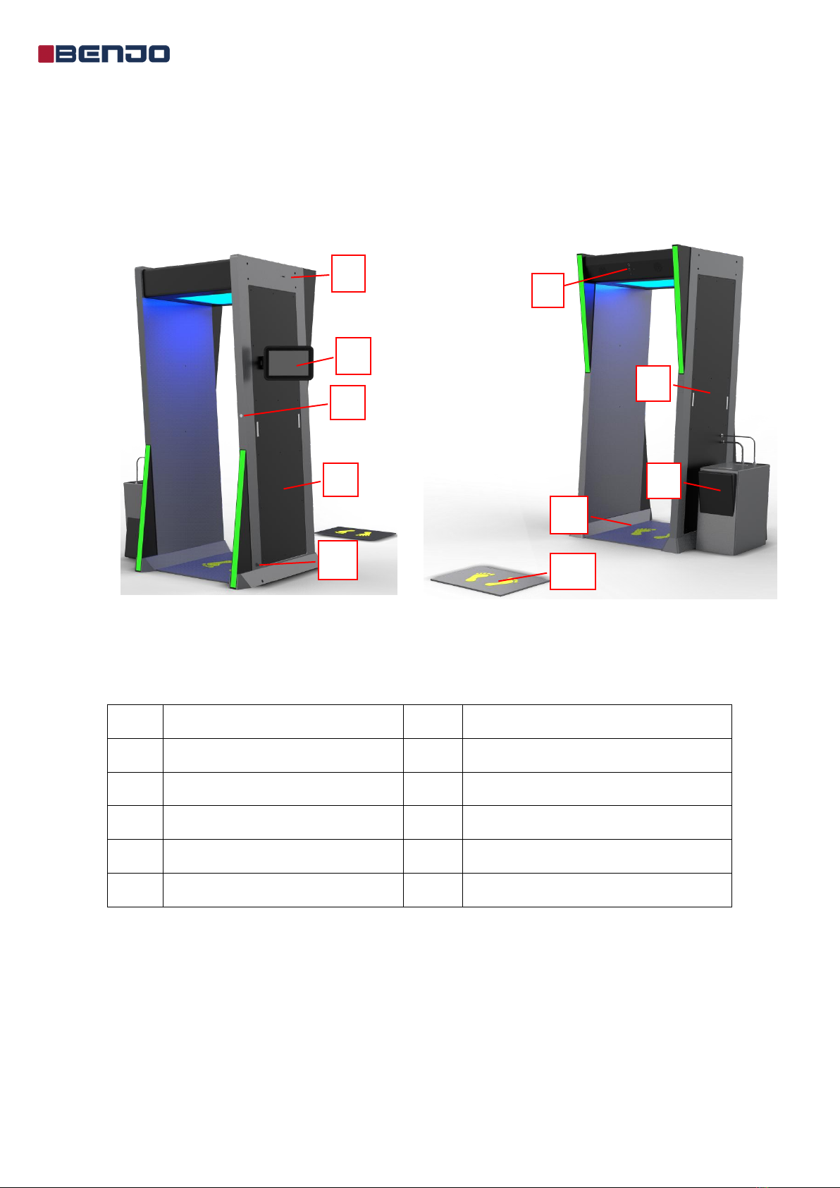
2.2 Structure of the system
The temperature disinfection system is mainly composed of the following parts:
main body of the channel, tank of disinfectant, display, thermal imaging camera and
etc.
Figure 2.1 Back of the system Figure 2.2 Front of the system
No. Name No. Name
1 USB port 6 Infrared thermal imaging camera
2 Display 7 The right panel of the system
3 Power button 8 Tank of disinfectant
4 The left panel of the system 9 Disinfection area
5 Power in 10 Temperature detection area
2
4
1
5
8
9
10
6
3 7

4
2.3 Specification
The specification for the IRD120A system is as below;
Items Parameter
Model No. IRD 120
Capacity of photos 50,000
Operation system Android7.0
Working temperature 0~45℃
Information record NO
Detection distance 1.5m
Detection accuracy ±0.3/±0.5℃
Lack of liquid Alarm Yes
Power 200W
Dimension 1m×1m×2.2m
Basic functions Record and query, disinfection, infrared thermal imaging
temperature detection and abnormal alarm
Optional functions Hand induction disinfector and alcohol concentration
detection
5
3. Installation
This chapter is the installation instruction for IRD120A temperature disinfection system, which
will help the operator to complete the installation easily.
The system is mainly composed by four parts: left shell of main body, right shell , top shell
and disinfectant tank.
Step 1: According to the structure picture and below pictures of the system, fix the right shell, left
shell of main body and the top shell with the hexagon socket wrench and eight hexagon socket
screws provides by the manufacture.
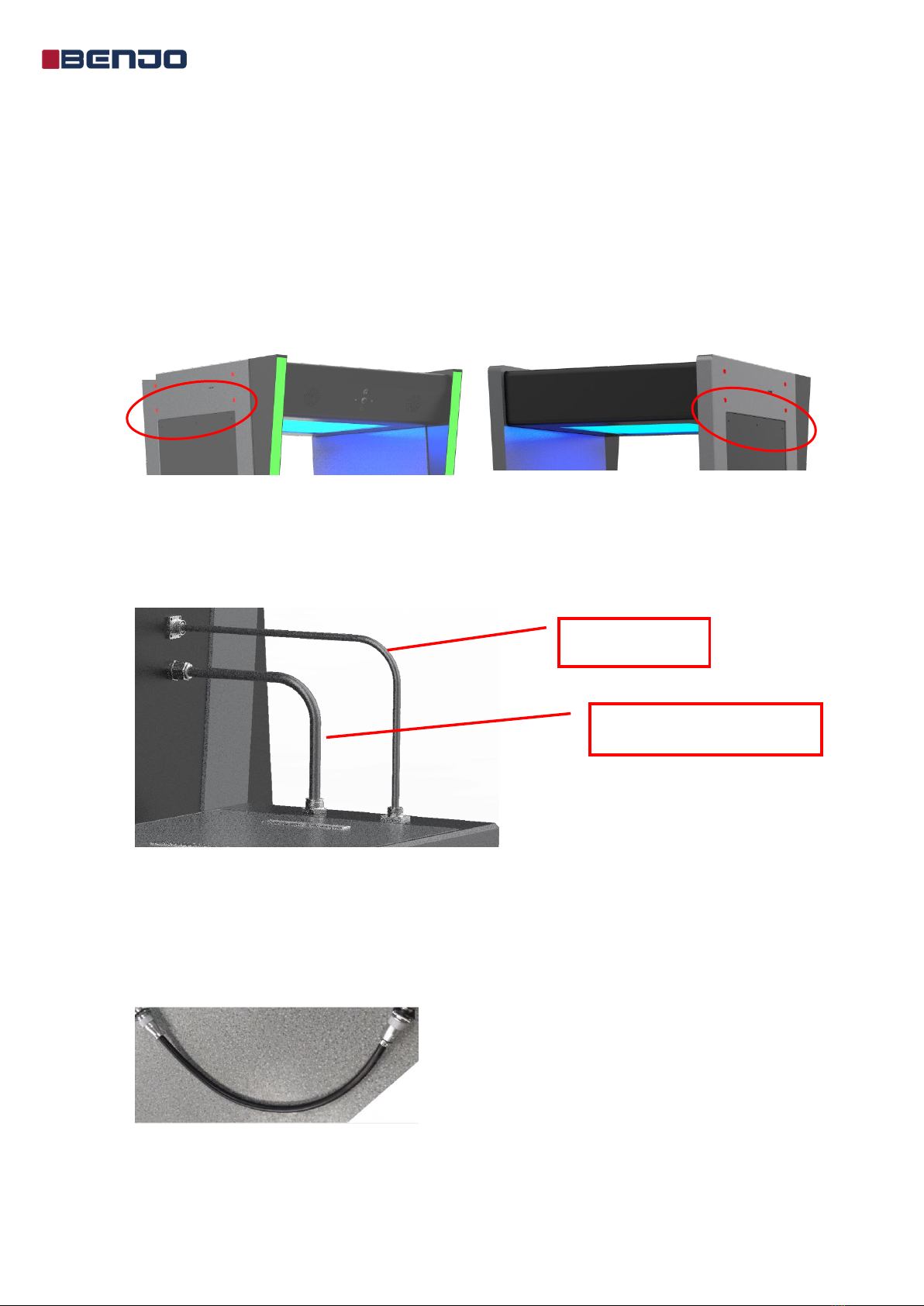
Figure 3.1 Main shell
Step 2: Place the disinfectant tank on the right side of the IRD120A systemmain body as shown in
the system structure picture, insert the hard water pipe on the right shell of the main body into the
quick connector of the disinfectant tank.
Figure 3.2 Disinfectant tank
Steps 3: You will find the water pump connection cable from the spare parts package, connect the
two sides of the cable to the corresponding port on the right shell of main body and the disinfectant
tank shown as picture 3.2, tighten it.
Figure 3.3 Water pump connection cable
Hard water pipe
Water pump connection cable
6
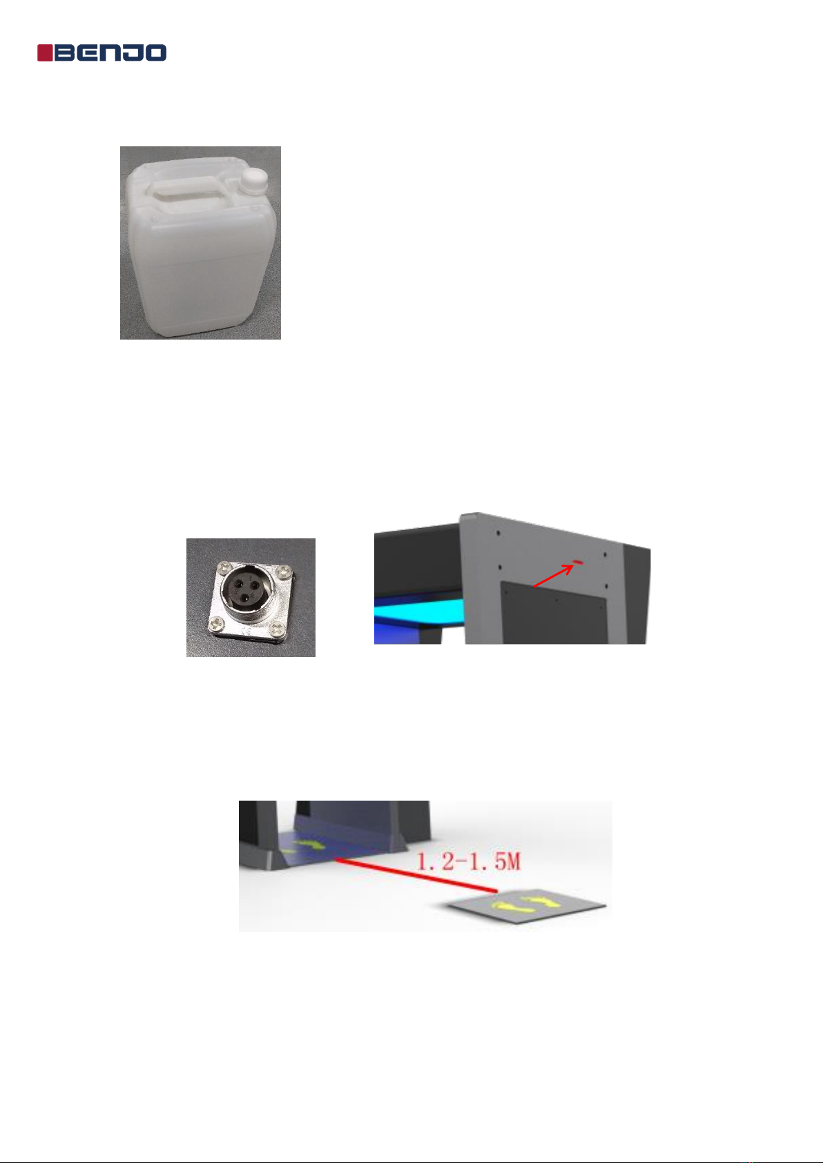
Step 4: Open the upper cover of the disinfectant tank and the cap of the disinfectant bucket, fill 20L
disinfectant to the bucket and tighten the cap of the bucket, close the upper cover of the tank.
Figure 3.4 Bucket of disinfectant
Note:The capacity for the bucket of disinfectant is 20L, please check whether the disinfectant
is sufficient or not after use.
Step 5: Connect the power cord to the power in port on the left shell of the main body, and connect
the USB disk we offered to the USB1 port on the left shell of the main body.
Figure 3.5 Power in port Figure 3.6 USB1 port for USB disk
Step 6: Place the pad to the right position in front of the channel. The distance from the pad to the
system main body is around 1.2m to 1.5m.
Figure 3.7 Temperature detection point

7
4. Instructions of use
4.1 Turn on the system
Connect the power cord into the AC 200-240V (100-120V optional) power socket,
press the power button on the left shell of the main body, the system will power on,
and you can see the display as below picture.
Figure 4.1 Welcome page of screen
4.2 Temperature detection
When people walk to the temperature detection point, looking up at the green indicator light in
picture 4.3, it will auto focus, and the system will announce the temperature value by voice. When
the body temperature exceeds the alarm threshold, the red LED light flashes and voice alarm as
well.
Figure 4.2 The green indicator light
8
4.3 Disinfection
After heard the voice broadcast “xx normal”, walk into the disinfection channel, and stay in
the disinfection channel for 1 second. The spraying nozzles will disinfect the surface of whole body
from different angles.
Note: There are 8 disinfectant spraying nozzles and 2 photoelectric sensors on each side in the
channel, the photoelectric sensors will switch on the corresponding spraying nozzles
according to the height of the people who walks in.
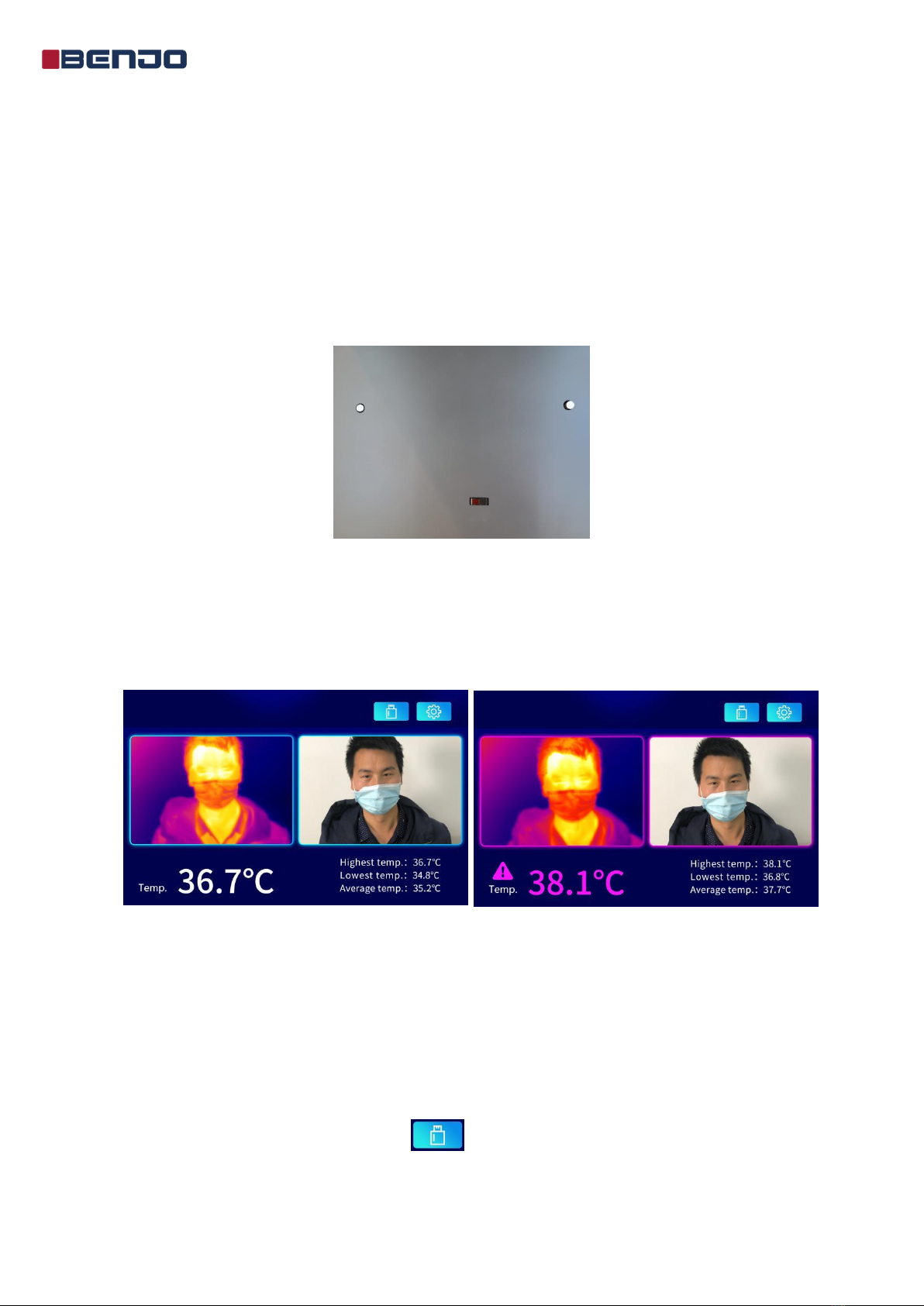
Figure 4.3 Photoelectric sensor and spraying nozzles
4.4 Real-time monitoring
The staff can watch the screen and monitor the body temperature of people who walk through
in real time.
Figure 4.4 Abnormal Figure 4.5 Abnormal
Note:1. Lowest temp./highest temp./average temp.: shows the current body temperature for the
people who walk in.
2. The camera at the top of the channel will take pictures with thermal imaging camera for
people coming and going. The staff can download the record data and view the records
without missing any suspect by inserting the USB disk into the port on the left shell of the
channel main body and click the icon on the upper right corner of the screen.
Table of contents


