A/DA PLATINUM II User manual
PLATINUM II
ZONE CONTROL SYSTEM
INSTALLATION MANUAL

2
TABLE OF CONTENTS
3
1
1.Precautions 2
2.EnvironmentalInformation 2
3.ComponentsSupplied 3
4.OptionalComponents 3
5.MountingtheControlBox 4
6.ConnectingtheZoneDampers 4
7.MountingtheTouchScreen 5
8.ConfiguringforMultipleSystems 6
9.ManualSystemSetup 7
10.DetectComponents 7
11.NameZones 9
12.ZoneSetUp 11
13.AccessingSystemSetUp 14
14.ResetDefaults 15
15.AddingaZone 16
16.Warranty 18
17.Troubleshooting 19
1
PLATINUM II

3. Components Supplied
Touch Screen Control Box
240V AC Power Cord Low Voltage Coms Cable (15m)
2 x Instruction Manuals
4. Optional Components
Secondary Touch Screen with Low Voltage Coms Cable (30m)
1. Precautions
Refer to these installation instructions before commencing the installation or
service of this product.
WARNING
This product should be installed and setup by qualified personnel.
To reduce the risk of fire, electric shock or product damage:
DO NOT expose to rain or moisture of any kind
DO NOT place articles filled with water on or near this appliance
DO NOT remove covers – there are no serviceable part inside
DO use only genuine Air Diffusion Agencies components
Ensure all electrical connections are made before connecting power to the
Control Box.
Installation setup changes should only be attempted by qualified personnel.
2. Environmental Information
This product (including packaging) is manufactured from fully recyclable
components. Please dispose of in an appropriate manner.
RECYCLE
PRECAUTIONS
INSTALLATION MANUAL
PLATINUM II
23
COMPONENTS SUPPLIED
ŸRecord the position and size of each Zone Damper on the record sheet in the
back of this manual
ŸThe Zone Damper cables should plug into the Control Box starting at position
number 1. The remaining cables are plugged into adjacent consecutive sockets.
7. Mounting the Touch Screen
ŸMount the Touch Screen close to the air conditioner control so they can be
programmed and monitored together.
ŸAvoid mounting in direct sunlight.
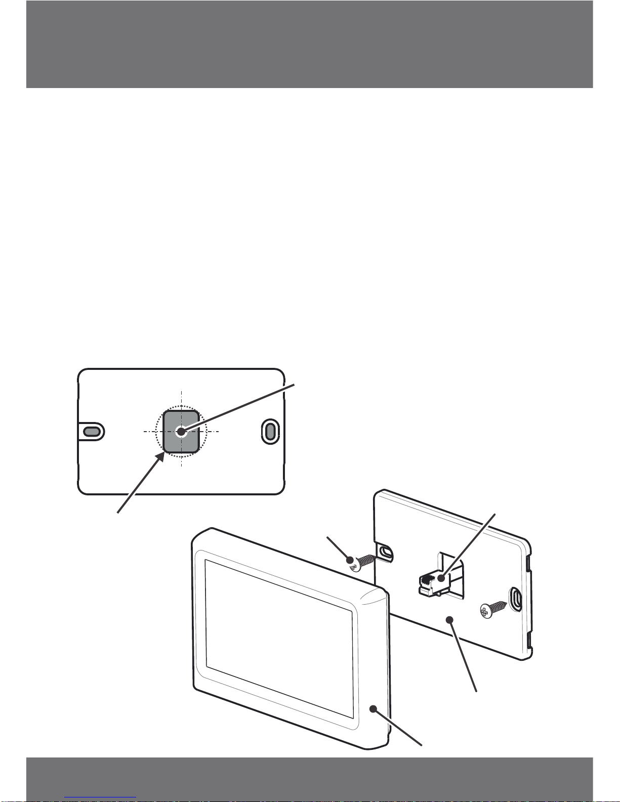
ŸThe Mounting Plate is used as a template for marking the wall before
mounting. A minimum 25mm diameter hole is required in the wall to
accommodate the socket on the back of the Touch Screen.
ŸThe Mounting Plate can be attached to a wall using or a
standard wall switch bracket. supplied fixings
5. Mounting the Control Box
ŸMount the Control Box in the roof space in a location central to all of the Zone
Dampers, ideally near a ceiling access panel.
ŸMount in a well ventilated area.
ŸThe Control Box should be screwed to the roof structure at a level to provide
easy access for the connection of wires.
DO NOT cover the Control Box with insulation
DO NOT mount below water heaters.
DO NOT mount near or below water pipes.
DO NOT mount near power cables or other sources of electrical noise.
ŸThe last step is to plug in the power cord to a standard power outlet. The
power outlet must be fitted by a licenced electrician.
DO NOT power up the Control Box until all connections are made.
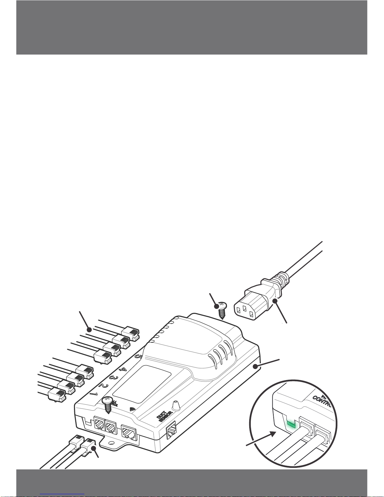
6. Connecting the Zone Dampers
ŸPlug in the Zone Damper cables to the Control Box.
Touch Screen
Mounting Plate
Mounting Screw
Coms Cable
MOUNTING THE CONTROL BOX
INSTALLATION MANUAL
PLATINUM II
45
MOUNTING THE TOUCH SCREEN
Plug Coms Cable into socket on the back of
the Touch Screen, then simply push onto
the Mounting Plate so it clips into place
240VAC
Power Cord
Control Box
Zone Damper Cables
Touch Screen Cable(s)
Mounting Screw
LED light
indicates
power
NOTE: Ensure wall behind opening in
Mounting Plate is completely clear
Ø25
ŸRecord the position and size of each Zone Damper on the record sheet in the
back of this manual
ŸThe Zone Damper cables should plug into the Control Box starting at position
number 1. The remaining cables are plugged into adjacent consecutive sockets.
7. Mounting the Touch Screen
ŸMount the Touch Screen close to the air conditioner control so they can be
programmed and monitored together.
ŸAvoid mounting in direct sunlight.
ŸThe Mounting Plate is used as a template for marking the wall before
mounting. A minimum 25mm diameter hole is required in the wall to
accommodate the socket on the back of the Touch Screen.
ŸThe Mounting Plate can be attached to a wall using or a
standard wall switch bracket. supplied fixings
5. Mounting the Control Box
ŸMount the Control Box in the roof space in a location central to all of the Zone
Dampers, ideally near a ceiling access panel.
ŸMount in a well ventilated area.
ŸThe Control Box should be screwed to the roof structure at a level to provide
easy access for the connection of wires.
DO NOT cover the Control Box with insulation
DO NOT mount below water heaters.
DO NOT mount near or below water pipes.
DO NOT mount near power cables or other sources of electrical noise.
ŸThe last step is to plug in the power cord to a standard power outlet. The
power outlet must be fitted by a licenced electrician.
DO NOT power up the Control Box until all connections are made.
6. Connecting the Zone Dampers
ŸPlug in the Zone Damper cables to the Control Box.
Touch Screen
Mounting Plate
Mounting Screw
Coms Cable
MOUNTING THE CONTROL BOX
INSTALLATION MANUAL
PLATINUM II
45
MOUNTING THE TOUCH SCREEN
Plug Coms Cable into socket on the back of
the Touch Screen, then simply push onto
the Mounting Plate so it clips into place
240VAC
Power Cord
Control Box
Zone Damper Cables
Touch Screen Cable(s)
Mounting Screw
LED light
indicates
power
NOTE: Ensure wall behind opening in
Mounting Plate is completely clear
Ø25
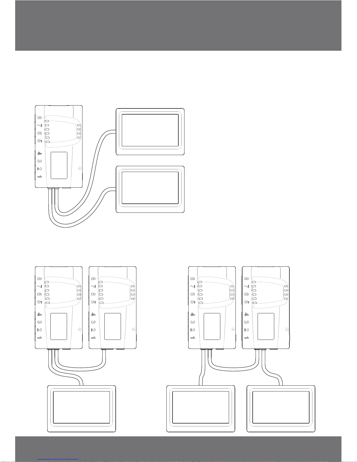
8. Configuring for Multiple Systems
Two Touch Screens can be linked to one Control Box - this is particularly useful
for 2-storey building applications. Simply plug the additional Coms cable and
Touch Screen into the Control Box.
Two Control Boxes can also be linked to create a maximum 16 zone system, using
one or two Touch Screens.
9. System Set Up
When the Touch Screen is first
powered up, the system will
check the installed
components during the
initialization process. (This will
also occur following a power
interruption.)
Once the initialization process
is complete, the System Set Up
screen is displayed.
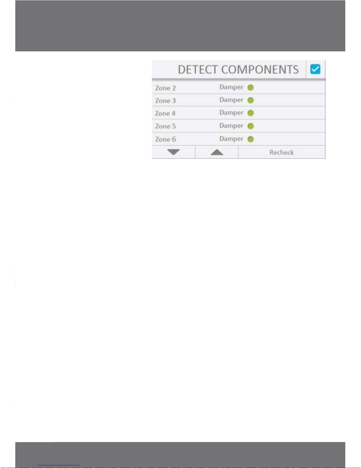
10. Detect Components
MULTIPLE SYSTEMS
INSTALLATION MANUAL
PLATINUM II
67
SYSTEM SET UP

8. Configuring for Multiple Systems
Two Touch Screens can be linked to one Control Box - this is particularly useful
for 2-storey building applications. Simply plug the additional Coms cable and
Touch Screen into the Control Box.
Two Control Boxes can also be linked to create a maximum 16 zone system, using
one or two Touch Screens.
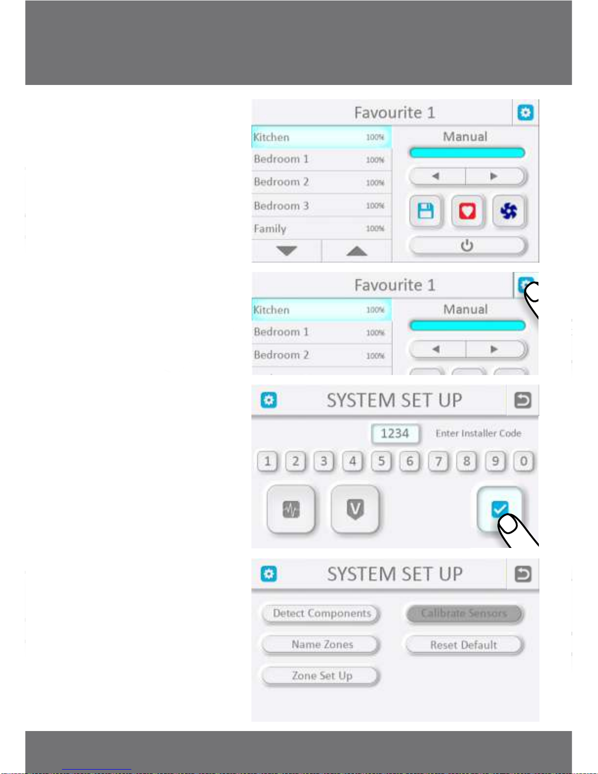
9. System Set Up
When the Touch Screen is first
powered up, the system will
check the installed
components during the
initialization process. (This will
also occur following a power
interruption.)
Once the initialization process
is complete, the System Set Up
screen is displayed.
10. Detect Components
MULTIPLE SYSTEMS
INSTALLATION MANUAL
PLATINUM II
67
SYSTEM SET UP

If the Zone Dampers have been
installed correctly, all Zone
Damper detections should be
indicated with a green light. If
there is a problem with a Zone
Damper or it cannot be
detected, it will be indicated
with a red light.
A simple 'Recheck' may resolve
the issue. If this does not
resolve the issue, it may be
necessary to investigate Zone
Damper components, faulty
cables or plug
connections.
NOTE: The system will
continue the set up process
even if components are left
undetected, however a 'Fault'
icon will appear for the
relevant Zone on the Base
Screen after the set up process
is complete.
Press the icon to exit
screen and continue.
'Esc'
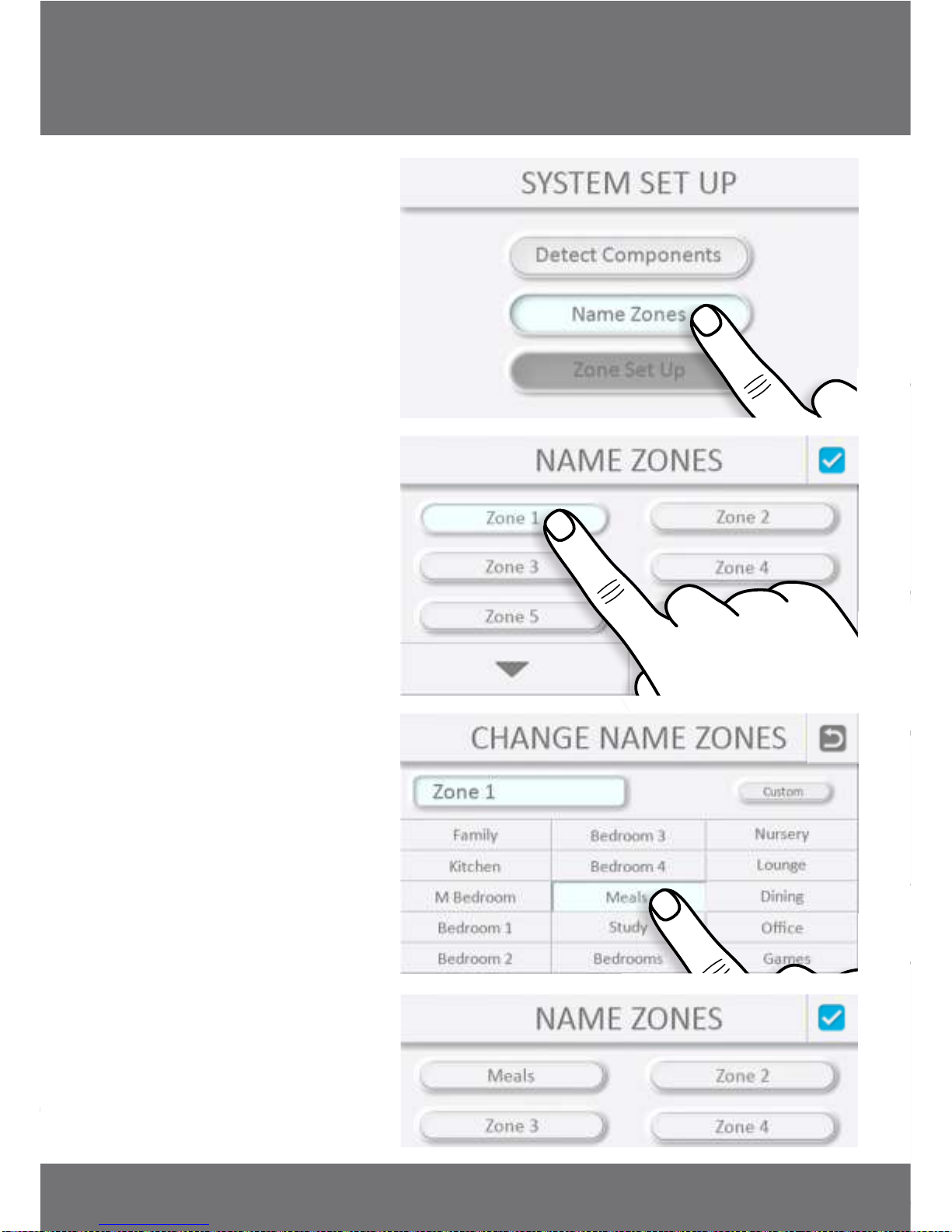
11. Name Zones
SYSTEM SET UP
INSTALLATION MANUAL
PLATINUM II
89
SYSTEM SET UP
If the Zone Dampers have been
installed correctly, all Zone
Damper detections should be
indicated with a green light. If
there is a problem with a Zone
Damper or it cannot be
detected, it will be indicated
with a red light.
A simple 'Recheck' may resolve
the issue. If this does not
resolve the issue, it may be
necessary to investigate Zone
Damper components, faulty
cables or plug
connections.
NOTE: The system will
continue the set up process
even if components are left
undetected, however a 'Fault'
icon will appear for the
relevant Zone on the Base
Screen after the set up process
is complete.
Press the icon to exit
screen and continue.
'Esc'
11. Name Zones
SYSTEM SET UP
INSTALLATION MANUAL
PLATINUM II
89
SYSTEM SET UP
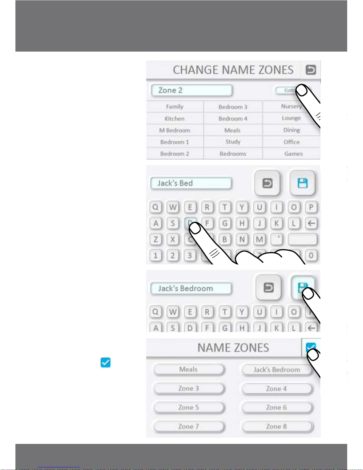
Alternatively for a custom
name:
When all Zones have been
named, press the icon to
exit screen and continue.
'Esc'
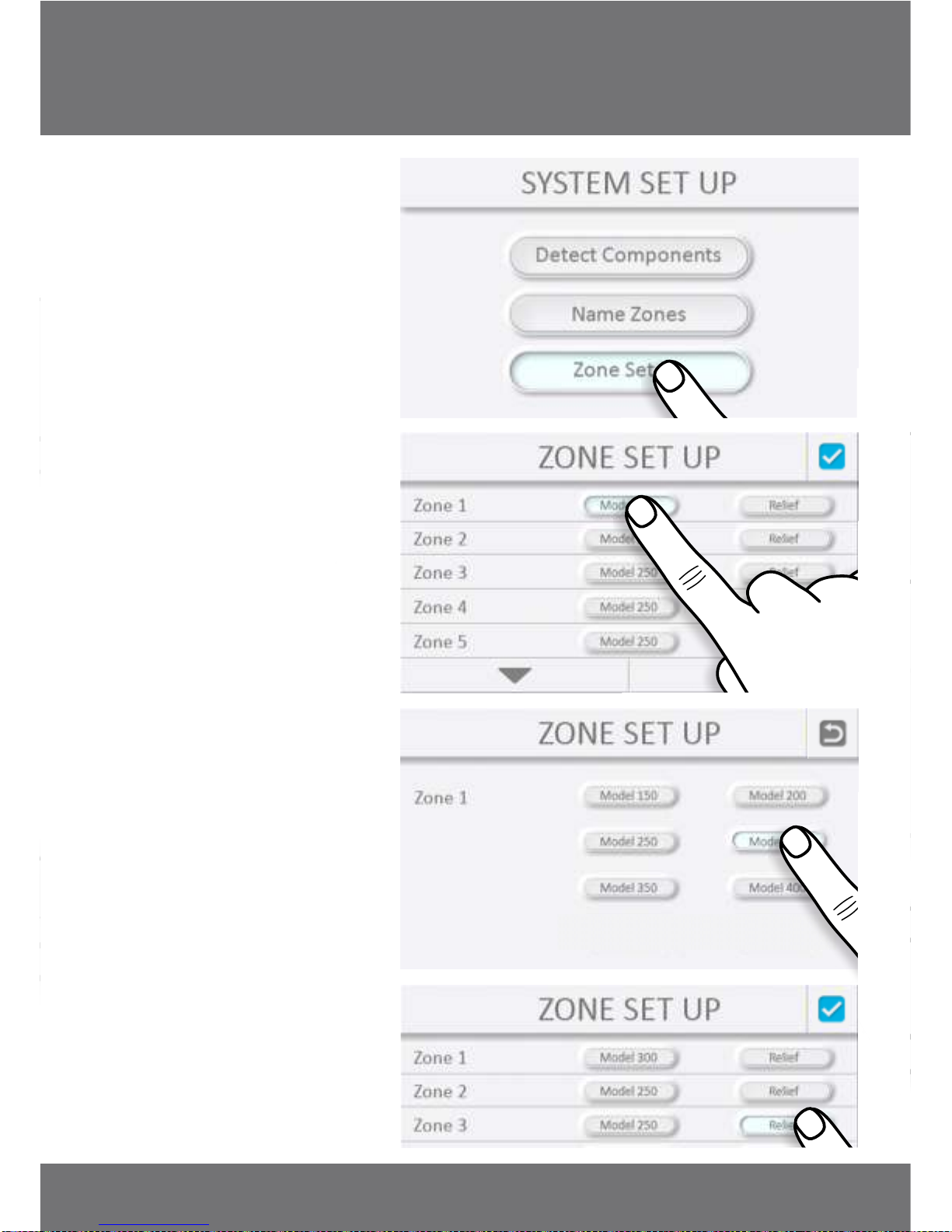
12. Zone Set Up
It is important to set the
diameter of each Zone Damper
to ensure the Relief Zones
function correctly.
To set Relief Zones, press the
relevant icon(s) that well serve
as Relief Zones.
INSTALLATION MANUAL
PLATINUM II
10 11
SYSTEM SET UP SYSTEM SET UP
Alternatively for a custom
name:
When all Zones have been
named, press the icon to
exit screen and continue.
'Esc'
12. Zone Set Up
It is important to set the
diameter of each Zone Damper
to ensure the Relief Zones
function correctly.
To set Relief Zones, press the
relevant icon(s) that well serve
as Relief Zones.
INSTALLATION MANUAL
PLATINUM II
10 11
SYSTEM SET UP SYSTEM SET UP
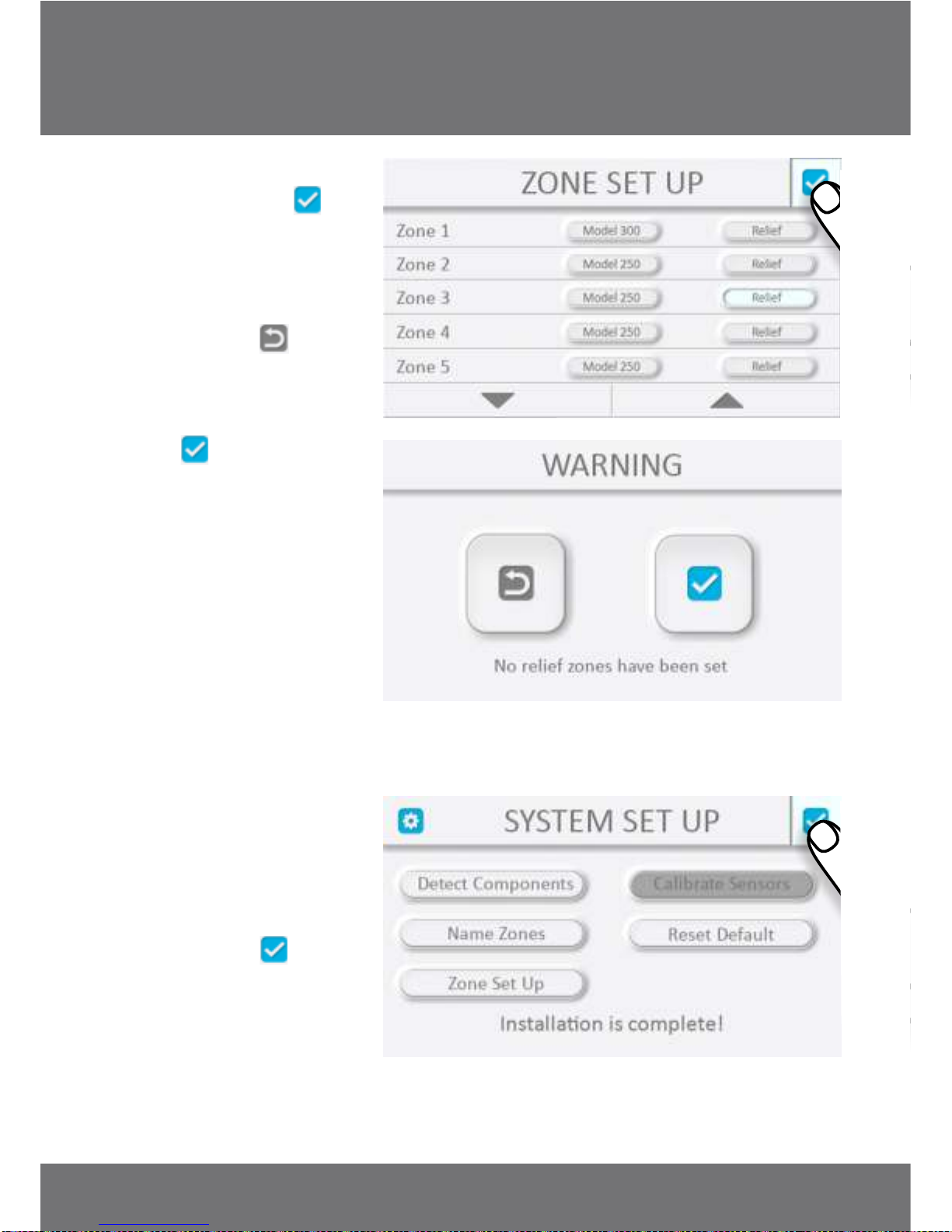
Once all Zones have been
configured press the icon
to exit screen and continue.
If no Relief Zones have been
set a warning screen will
display. Pressing will
return the display to the
previous Zone Set Up screen so
Relief Zones can be set.
Pressing confirms
acceptance no Relief Zones are
set.
NOTE: If no Relief Zones have
been set there must be a Zone
where no Damper is fitted to
allow for the minimum airflow
requirement and prevent any
damage to the air conditioning
system.
At this point there will be
optional System Set Up
functions that can be used –
these are detailed later.
Otherwise installation is now
complete – press to
continue.
'Esc'
'Esc'
'OK'
‘OK’
The Base Screen will now be
displayed ready for use.
Refer to Owners Manual for
changing Zone Settings and
adding Favourites.
13. Accessing System Set
Up
After initial installation, access
to System Set Up functionality
can be obtained by pressing
the icon in the top right corner
and will require a 4-digit
installer code.
INSTALLATION MANUAL
PLATINUM II
12 13
SYSTEM SET UP SYSTEM SET UP
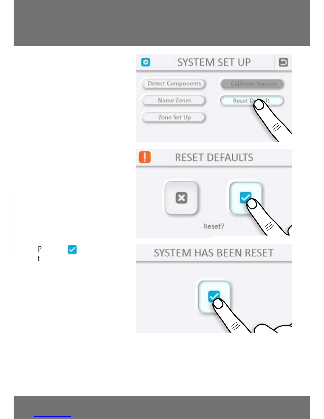
14. Reset Defaults
This will remove all
user/installer saved
information and return the
system to its original factory
settings.
Pressing will reinitialize
the system then return to the
System Setup screen as shown
during an initial set up.
'OK'
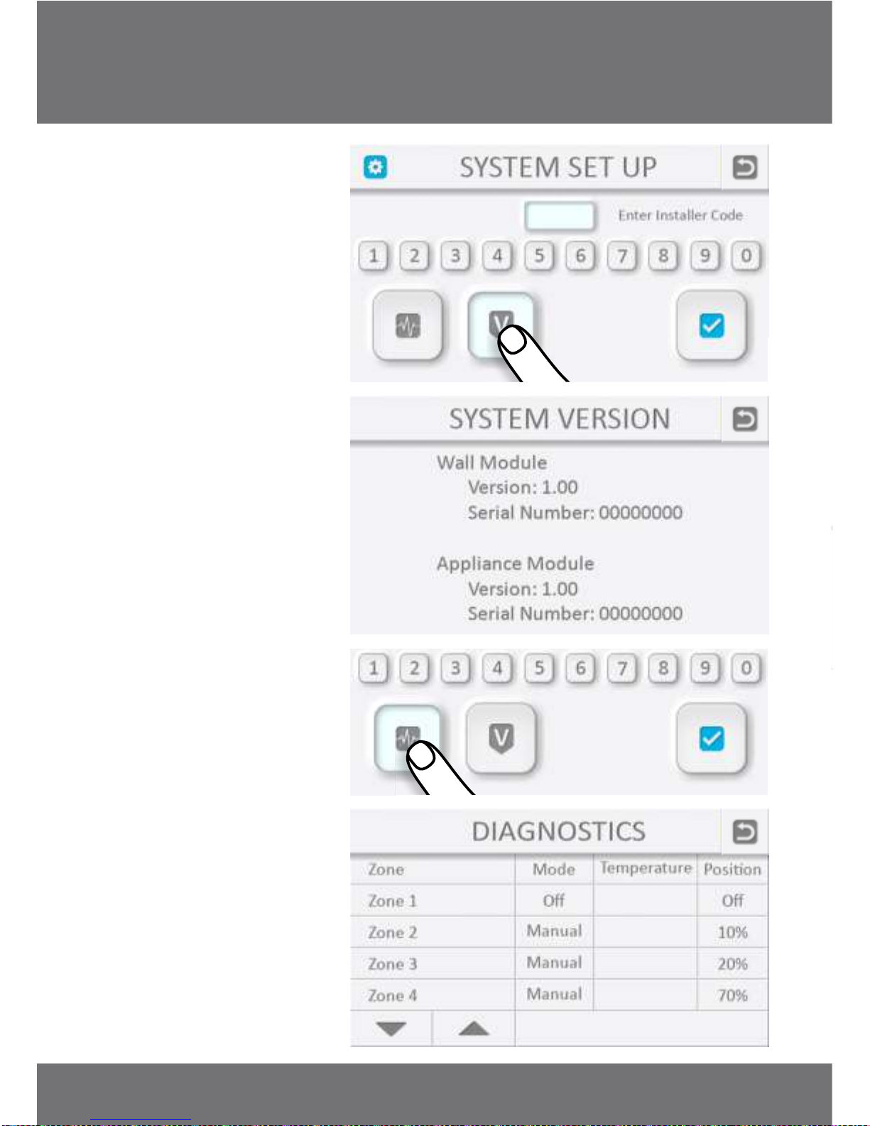
Access to System Version and
Diagnostic information are also
available from this screen. This
information may be useful in
the event of a service call.
SYSTEM SET UP SYSTEM SET UP
INSTALLATION MANUAL
PLATINUM II
14 15
14. Reset Defaults
This will remove all
user/installer saved
information and return the
system to its original factory
settings.
Pressing will reinitialize
the system then return to the
System Setup screen as shown
during an initial set up.
'OK'
Access to System Version and
Diagnostic information are also
available from this screen. This
information may be useful in
the event of a service call.
SYSTEM SET UP SYSTEM SET UP
INSTALLATION MANUAL
PLATINUM II
14 15
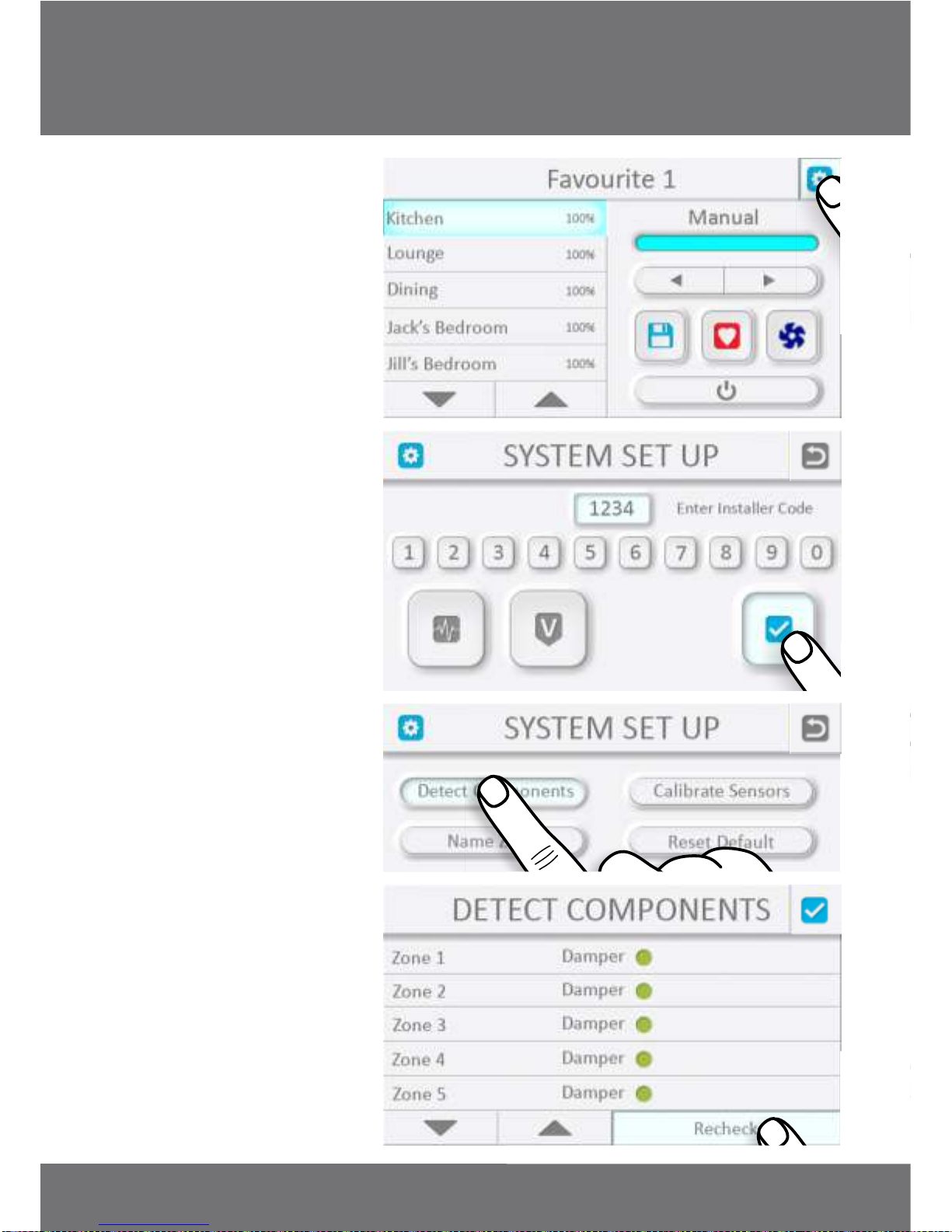
15. Adding a Zone
To add a Zone to the system,
once the new Zone Damper
has been installed, access the
System Set Up screen and
press Detect Components
button.
Press ‘Recheck’ to prompt the
system to search for
components.
If the component is detected
successfully, a new Zone
should appear with the
Damper indicated by a green
light.
Follow the previous procedure
for naming the Zone and
configuring the size.
INSTALLATION MANUAL
PLATINUM II
16 17
SYSTEM SET UP SYSTEM SET UP

17. Troubleshooting
All service to the Platinum II system must be carried out by an approved Air Diffusion
Agencies service technician, and must not be done by unqualified personnel. Repairs
carried out by unqualified personnel will void warranty.
16. Warranty
Subject to the conditions below, this product is guaranteed against any defects in
materials or workmanship under conditions of normal use for a period of 12 months
from date of purchase.
The benefits conferred by this warranty are in addition to other warranties and remedies
that are implied under the Trade Practices Act and similar State and Territory laws.
Subject to statutory rights the goods will not be eligible for service under this warranty if:
a) Proof of purchase cannot be provided.
b) The defect was caused by an accident, misuse, abuse, improper installation or
operation, lack of reasonable care, vermin infestation, unauthorised modifications,
loss of parts, tampering or attempted repair by a person not authorised by Air
Diffusion Agencies.
c) The product has been damaged by lightning or mains power surge.
d) The product has been used for other than its intended use.
Subject to your statutory rights:
a) Any claim under this warranty is limited to the repair or replacement of the
product and does not include installation cost, travelling cost or freight charges.
b) All claims must be returned to Air Diffusion Agencies or its agents at the claimant's
expense.
c) If the goods are found to be in sound working order by the authorised service
centre, you may be charged a fee for the service and for any other direct costs
associated with having the product delivered for service.
d) This warranty is not transferrable and is only available to the original purchaser.
Problem
Cause
Solution
Touch Screen has
no display
Coms cable not plugged in.
Power cable not plugged into
Control Box.
Power point not switched on at
Control Box.
No power at power outlet.
Circuit breaker tripped.
Check plug connection in back of
Touch Screen and at Control Box.
Check power plug connection at
Control Box.
Switch on the power point.
Check fuses, circuit breakers, call
electrician.
Re-set.
If problem persists call service
technician.
Touch Screen
displays
”Fault in damper”
Damper unplugged.
Faulty Damper.
Faulty Damper motor.
Faulty motor cable.
Check connections at the
Control Box and at the Damper
motor.
Replace Damper.
Replace Damper motor.
Replace motor cable.
Touch Screen
displays
“Communication
Failure”
Missed communication from
Control Box.
Turn off power supply at fuse
box or power point for 10
seconds.
Replace Coms cable.
If problem persists call service
technician.
Touch Screen is
working but one
Zone is not
regulating the
airflow
Broken damper blade.
Blade is obstructed.
Duct not properly connected.
Replace damper.
Remove obstruction.
Check duct connection.
WARRANTY TROUBLESHOOTING
INSTALLATION MANUAL
PLATINUM II
18 19
Air Diffusion Agencies strive to implement continuous product improvement,
therefore specifications are subject to change without notice.
Other manuals for PLATINUM II
2
Table of contents
Other A/DA Control System manuals


