Page
1
T: +44 (0) 20 8398 8011
Expo Technologies US
T: +1 (440) 247 5314
Expo Technologies China
T: +86 532
8906 9858
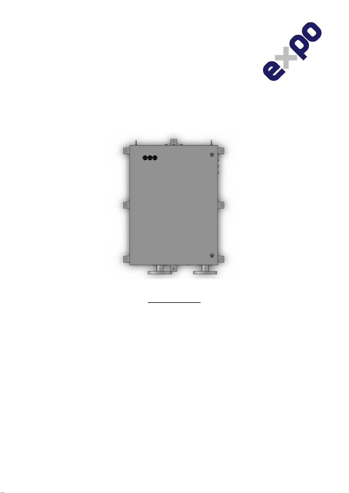
1. D801 MiniPurge
- General System Specification
Pressurized Motor Housing
Pressurized Motor Enclosure : A range of Electrical Motor housings
Classification : Zone 1 Group IIC
Volume (Litres) : Various, system settings determined by motor manufacturer.
Total Purge Flow Rate : To be supplied by customer and must include flow to compensate for leakage.
Estimated Purge Time : To be determined by 10 x volume.
Contents of Enclosure : Electrical motor.
Access covers : Special Tool required or Key Operated, door Interlock System not required.
Enclosure Pressure : Normal: 10 mbarg. (Alternative set-points are available) This is also the set
point of the Automatic Leakage Compensation Pressure Sensor (CLAPS
Sensor)
Enclosure Test Pressure : Motor Test Pressure = Relief Valve opening pressure x 1.5
MiniPurge
Control Unit Data
Model Number : 7XLC/ss/ET/OV/PA/PC Special Design Number: D801SYS
Option codes : ET = Electronic Purge Timer
: OV = Outlet Valve is pneumatically operated
: PA = Integral Ex e Power & Alarm terminal box
: PC = Pressurized Enclosure (Motor) Pressure Control Automatic
Leakage Compensation Valve (CLAPS system)
Action on Pressure Failure : Alarm and Trip (Isolate power / motor) User adjustable “Alarm Only”
System Type : ThinMani MiniPurgeSystem
Type of Operation : Automatic Leakage Compensation using the "Closed Loop Automatic
Pressurization System" (CLAPS)
Purge Flow Capacity : Up to 0.25m3/s (14,000 Nl/min) @ 420kPag (4.2 barg) inlet pressure. See
individual system specification sheet
Leakage Compensation
Capacity : Up to 0.085m3/s (5100 Nl/min) @ 420kPag (4.2 barg) inlet pressure
Enclosure Type : Stainless Steel 316
Mounting method : Wall mounting lugs & spacers. Fixing holes as per drawing D801-GA.
Temperature Limits : -20ºC to +55ºC ambient temperature.
Supply Pressure : Clean Dry Oil Free Air or Inert Gas. Pressure 420 – 800kPag (4.2 - 8 barg).
50 micron automatic drain supply Inlet filter & 1.6MPag (16 barg) regulator fitted.
Logic Regulator & Gauge : Fitted. Set to 230kPag (2.3 barg).
CLAPS Regulator & Gauge : Set to system requirements
Process Connections : Purge Supply: ANSI 150 B16.5 flange (size as per customer specification).
Outlet to Motor: ANSI 150 B16.5 flange (size as per customer specification).
Minimum Supply Line 50mm (2”) I.D Pipe
Reference points & signals: 1/8” NPT female
Visual Indicators : Alarm/Pressurized (Red / Green)
: Intermediate Low Pressure (Red / Green)
: System Purging (Black / 4 x Yellow LEDs to indicate elapsed time)
Motor Interlock Switch : DPNO electrical switch, contact ratings AC-15 250 Vac 4 Amps,
Ex d IIC T6
Low Pressure Switch : SPNO electrical switch, contact ratings AC-15 250Vac 4 Amps,
Ex d IIC T6
Intermediate Switch : SPNO electrical switch, contact ratings AC-15 250 Vac 4 Amps,
Ex d IIC T6
Signal Junction box : Stainless Steel, Ex e IIC T5 Gb (Tamb -20ºC to 55ºC) IP66 / Ex e IIC T4 Gb
(Tamb -20ºC to 60ºC) IP66. Mounted inside D801 system c/w terminals, front
access cover & access for glands on bottom of D801 system.