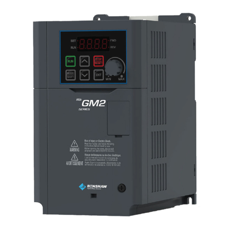
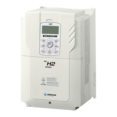
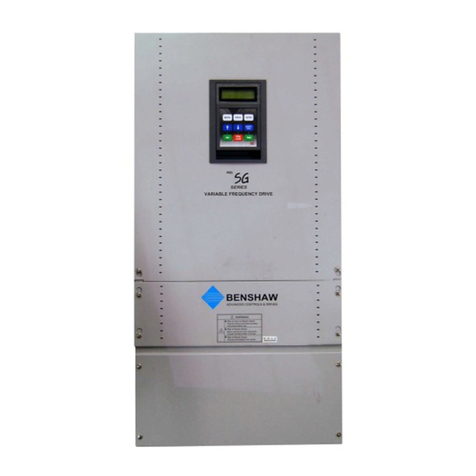
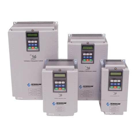
BENSHAW Rsi S Series User manual

890049-00-00
© 2016 Benshaw Corporation
Benshaw retains the right to change specifications and illustrations in text without prior notification.
The contents of this document may not be copied without the explicit permission of Benshaw.
Rsi S Series
Low Voltage
Variable Frequency Drive
Instruction Manual
Rsi S Series
Low Voltage
Variable Frequency Drive
Instruction Manual


iii
Safety Information
Safety Information
Read and follow all safety instructions in this manual precisely to avoid unsafe operating conditions,
property damage, personal injury, or death.
Safety symbols in this manual
Indicates an imminently hazardous situation which, if not avoided,
will
result in severe inj
ury or death
.
Indicates a potentially
hazardous situation which, if not avoided, could result in injury or death.
Indicates a potentially hazardous situation that, if not avoided, could result in
minor injury or
property
damage.
Safety information
•
Do not open the cover of the equipment while it is on or operating. Likewise, do not operate the
inverter while the cover is open
. xposure of high voltage terminals or charging area to the
external environment may result in an electric shock. Do not remove any covers or touch the
internal circuit boards (PCBs) or electrical contacts on the product when the power is on or
during operation. Doing so may result in serious injury, death, or serious property damage.
•
Do not open the cover of the equipment even when the power supply to the inverter has
been turned off unless it is necessary for maintenance or regular inspection. Opening the
cover may result in an electric shock even when the power supply is off
.
•
The equipment may hold charge long after the power supply has been turned off. Use a multi-
meter to make sure that there is no voltage before working on the inverter, motor or motor cable.
•
This equipment must be grounded for safe and proper operation.
•
Do not supply power to a faulty inverter. If you find that the inverter is faulty, disconnect the
power supply and have the inverter professionally repaired.
•
The inverter becomes hot during operation. Avoid touching the inverter until it has cooled to
avoid burns
.
•
Do not allow foreign objects, such as screws, metal chips, debris, water, o
r oil to get inside the

Quick Reference Table
iv
inverter.
Allowing foreign objects inside the inverter m
ay cause the inverter to malfunction or
result in a fire
.
•
Do not operate the inverter with wet hands. Doing so may result in electric shock.
•
Check the information about the protection level for the circuits and devices.
The following connection terminals and devices are the lectrical Protection level 0 per I C -
61140. This means that the circuit protection level depends on the basic insulation. If there is no
basic insulation this may cause electric shock. When installing or wiring the connection terminals
and devices, take the same protective action as with the power wire.
- Multi-function Input: P1-P5, CM
- Analog Frequency Input: VR, V1, I2, TI
- Safety Function: SA, SB, SC
- Analog Output: AO, TO
- Contact: Q1, G, 24, A1, B1, C1, S+, S-, SG
- Fan
•
The protection level of this equipment (inverter) is the lectrical Protection level I.
•
Do not modify the interior workings of the inverter.
Doing so
will void the warranty.
•
The inverter is designed for 3-phase motor operation. Do not use the inverter to operate a single
phase motor.
•
Do not place heavy objects on top of electric cables. Doing so may damage the cable and
result in an electric shock.
Note
–
Short Ci
rcuit Current Rating, SCCR
Maximum allowed prospective short-circuit current at the input power connection is defined in I C
60439-1 as 100 kA. Depending on the selected MCCB, the “S” Series inverter is suitable for use in
circuits capable of delivering a maximum of 100 kA RMS symmetrical amperes when protected by a
100 kaic rated breaker or fuses.

v
Safety Information
Quick Reference Table
The following table contains situations frequently encountered while working with inverters. Refer
to the situations in the table to quickly and easily locate answers to your questions.
Situation Reference
I want to run a slightly higher rated motor than the inverter’s rated capacity.
p.348
I want to configure the inverter to start operating as soon as the power source i
s
applied. p. 81
I want to configure the motor’s parameters.
p.143
I want to set up sensorless vector control.
p.146
Something seems to be wrong with the inverter or the motor.
p.336
What is auto tuning? p.143
What are the recommended wiring lengths? p. 24
The motor is too noisy. p. 176
I want to apply PID control on my system. p. 135
What are the factory default settingss for P1
–
P5 multi-function terminals? p. 27
I want to view all of the parameters I have modified. p. 186
I want to review recent fault and warning histories. p. 302
I want to change the inverter’s operating frequency using a potentiometer. p. 52
I want to install a frequency meter using an analog terminal. p. 29
I want to display the supply current to motor. p. 55
I want to operate the inverter using a multi-step speed configuration. p. 75
The motor runs too hot. p. 213
The inverter is too hot. p. 5
I want to change the items that are monitored on the keypad. p. 207


Table of Contents
vii
Contents
1
Preparing the Installation ...................................................................................... 1
Product Identification .......................................................................................... 1
Part Names ........................................................................................................... 2
Installation Considerations .................................................................................. 4
Selecting and Preparing a Site for Installation ................................................... 5
Cable Selection ..................................................................................................... 9
2
Installing the Inverter .......................................................................................... 11
Mounting the Inverter ........................................................................................ 13
Cable Wiring ....................................................................................................... 17
Post-Installation Checklist ................................................................................. 35
Test Run .............................................................................................................. 37
3
Learning to Perform Basic Operations ............................................................. 39
About the Keypad .............................................................................................. 39
Learning to Use the Keypad .............................................................................. 43
Application xamples ........................................................................................ 47
Monitoring the Operation ................................................................................. 55
4
Learning Basic Features ....................................................................................... 59
Setting Frequency Reference ............................................................................ 62
Frequency Hold by Analog Input ....................................................................... 74
Changing the Displayed Units (Hz↔Rpm) ....................................................... 74
Setting Multi-step Frequency............................................................................ 75
Command Source Configuration ...................................................................... 77
Local/Remote Mode Switching ......................................................................... 79
Forward or Reverse Run Prevention ................................................................. 81
Power-on Run ..................................................................................................... 81
Reset and Restart ............................................................................................... 82
Setting Acceleration and Deceleration Times .................................................. 84
Acc/Dec Pattern Configuration ......................................................................... 88

Table of Contents
viii
Stopping the Acc/Dec Operation ...................................................................... 91
V/F(Voltage/Frequency) Control ....................................................................... 91
Torque Boost ......................................................................................................94
Output Voltage Setting ...................................................................................... 95
Start Mode Setting ........................................................................................... 96
Stop Mode Setting ............................................................................................. 97
Frequency Limit ............................................................................................... 100
2
nd
Operation Mode Setting ............................................................................ 102
Multi-function Input Terminal Control ............................................................ 103
P2P Setting ....................................................................................................... 105
Multi-keypad Setting ....................................................................................... 107
User Sequence Setting .................................................................................... 108
Fire Mode Operation ........................................................................................ 117
5
Learning dvanced Features ............................................................................ 119
Operating with Auxiliary References .............................................................. 120
Jog operation.................................................................................................... 125
Up-down Operation ......................................................................................... 128
3-Wire Operation.............................................................................................. 129
Safe Operation Mode ...................................................................................... 130
Dwell Operation ............................................................................................... 132
Slip Compensation Operation ......................................................................... 133
PID Control ....................................................................................................... 135
Auto Tuning ...................................................................................................... 143
Sensorless Vector Control for Induction Motors ............................................ 146
Sensorless Vector Control for PM (Permanent-Magnet) Synchronous Motors
154
Kinetic nergy Buffering (K B) Operation ..................................................... 165
Torque Control ................................................................................................. 168
nergy Saving Operation ................................................................................. 171
Speed Search Operation .................................................................................. 172
Auto Restart Settings ....................................................................................... 176

Table of Contents
ix
Operational Noise Settings (carrier frequency settings) ............................... 178
2nd Motor Operation ....................................................................................... 179
Supply Power Transition .................................................................................. 181
Cooling Fan Control ......................................................................................... 182
Input Power Frequency and Voltage Settings ................................................ 182
Read, Write, and Save Parameters ................................................................. 183
Parameter Initialization ................................................................................... 183
Parameter View Lock ....................................................................................... 184
Parameter Lock ................................................................................................ 185
Changed Parameter Display ........................................................................... 186
User Group ........................................................................................................ 186
asy Start On .................................................................................................... 188
Config(CNF) Mode ........................................................................................... 189
Timer Settings .................................................................................................. 190
Brake Control .................................................................................................... 191
Multi-Function Output On/Off Control ........................................................... 192
Press Regeneration Prevention ....................................................................... 193
Analog Output .................................................................................................. 195
Digital Output ................................................................................................... 200
Keypad Language Settings ............................................................................. 207
Operation State Monitor ................................................................................. 207
Operation Time Monitor .................................................................................. 210
6
Learning Protection Features ........................................................................... 213
Motor Protection ............................................................................................. 213
Inverter and Sequence Protection .................................................................. 220
Under load Fault Trip and Warning ................................................................. 223
Fault/Warning List ............................................................................................ 229
7
RS-485 Communication Features .................................................................... 231
Communication Standards ............................................................................. 231
Communication System Configuration .......................................................... 232

Table of Contents
x
Communication Protocol ................................................................................ 239
Compatible Common Area Parameter ........................................................... 241
xpansion Common Area Parameter ............................................................. 245
8
Table of Functions .............................................................................................. 255
Operation Group .............................................................................................. 255
Drive group (PAR→dr) ..................................................................................... 257
Basic Function group (PAR→bA) ....................................................................262
xpanded Function group (PAR→Ad) ........................................................... 268
Control Function group (PAR→Cn)................................................................. 273
Input Terminal Block Function group (PAR→In) ........................................... 280
Output Terminal Block Function group (PAR→OU) ...................................... 285
Communication Function group (PAR→CM) ............................................... 290
Application Function group (PAR→AP) ......................................................... 295
Protection Function group (PAR→Pr) ........................................................... 298
2nd Motor Function group (PAR→M2) .......................................................... 303
User Sequence group (US) .............................................................................. 305
User Sequence Function group(UF) ................................................................ 308
Groups for LCD Keypad Only .......................................................................... 329
9
Troubleshooting .................................................................................................. 333
Trips and Warnings ........................................................................................... 333
Troubleshooting Faults .................................................................................... 336
Troubleshooting Other Faults ......................................................................... 339
10
Maintenance ......................................................................................................... 345
Regular Inspection Lists ................................................................................... 345
Storage and Disposal ....................................................................................... 348
11
Technical Specification ....................................................................................... 351
Drive Ratings .................................................................................................... 351
Product Specification Details .......................................................................... 355
xternal Dimensions (IP 20 Type) .................................................................... 358

Table of Contents
xi
Fuse and Reactor Specifications ..................................................................... 363
Terminal Screw Specification .......................................................................... 364
Braking Resistor Specification ......................................................................... 365
Continuous Rated Current Derating ............................................................... 366
Heat mmission ............................................................................................... 368
12
pplying Drives to Single-Phase Input pplication .................................... 370
Introduction ...................................................................................................... 370
Power(HP), Input Current and Output Current............................................... 371
Input Frequency and Voltage Tolerance ......................................................... 371
Product Warranty ....................................................................................................... 372
UL mark ........................................................................................................................ 373
Manual Revision History ........................................................................................... 374

Preparing the Installation
0

Preparing the Installation
1
1Preparing the Installation
This chapter provides details on product identification, part names, correct installation and cable
specifications. To install the inverter correctly and safely, carefully read and follow the instructions.
Pro uct I entification
Product name and specifications are detailed on the nameplate (label). The illustration below
shows the nameplate. Check the nameplate before installing the product and make sure that the
product meets your requirements. For more detailed product specifications, refer to 11.1 Drive
Ratings.
N
ote
Check the product name
, open the packaging
,
and
then
confirm
that the product is
free from
defect
s
.
Contact your supplier if you have any issues or questions about your product.
Output
Specifications
RSI – 003 – SS – 4 – C
RSI – Benshaw Redi Start Inverter
003 – HP
001 – 1 HP
002 – 2 HP
003 – 3 HP
005 – 5 HP
007 – 7.5 HP
010 – 10 HP
SS – Benshaw “S” Series
4 – Voltage Class: 2 – 240V
4 – 480V
C – Open Chassis
(Nema/UL Open
type, IP
-
00
)
RSI-003-SS-4C
Input: 380 – 480V 3 Phase 50/60Hz.
HD: 5.9A ND: .5A
Output: 0-Input V 3 Phase 0.01 – 400 Hz.
HD: 5.5A ND: 6.9A
4.2 kVA
Ser. No.:
Inspected By:
Mo el Number
Power
Source

Preparing the Installation
2
Part Names
The illustration below displays part names. Details may vary between product groups.
Three Phase 230V / 460V
0.5 HP~5 HP (0.4~3.7kW )
Cooling fan
Cooling fan cover
Top cover
Inverter body
Keypad
Control terminal block
Front cover (L)
Front cover (R)
(Option)

Preparing the Installation
3
Three Phase 230V / 460V
7.5 HP~ 10 HP (5.5
–
––
–
7.5kW)
Cooling fan cover
Top cover
Inverter body
Control terminal cover
Front cover
Cable guide
Control terminal
block
Keypad
Cooling fan

Preparing the Installation
4
Installation Consi erations
The environment can significantly impact the lifespan and reliability of the product. The table below
details the ideal operation and installation conditions for the inverter.
Items
Description
Ambient Temperature* Heavy Duty: 14–104
°
F (-10–40
℃
) Normal Duty: 14–122
°
F (-10–
50
℃
)
Ambient Humidity
90% relative humidity (no condensation
)
Storage Temperature - 4–149
°
F (-20–65
℃
)
nvironmental Factors
An environment free
from
corrosive or
flammable gas
es
, oil
residue or dust
Altitude/Vibration
L
ower than
3,280 ft
(1,000 m)
above
sea level/
less than
1
G
(9.8m/sec2)
Air Pressur
e
20.7
–
31.3 inHg
(10
–
15 PSI,
70
–
106kPa
)
* The ambient temperature is the temperature measured at a point 2” (5 cm) from the surface of
the inverter.
Do not allow the ambient temperature to exceed the allow
able
range
while operating
the inverter.
See side by s
ide installation
on pages 7 and 8.
2”
2”

Preparing the Installation
5
Selecting an Preparing a Site for Installation
When selecting an installation location consider the following points:
•
The inverter must be installed on a wall that can support the inverter’s weight.
•
The location must be free from vibration. Vibration can adversely affect the long term
operation of the inverter.
•
The inverter can become very hot during operation. Install the inverter on a surface that is fire-
resistant or flame-retardant and with sufficient clearance around the inverter to allow air to
circulate. The illustrations below detail the required installation clearances.
See side by side installation on pages 7 and 8.
2” minimum 2” minimum
2” minimum
4” minimum
4” minimum

Preparing the Installation
6
•
nsure sufficient air circulation is provided around the inverter when it is installed. If the
inverter is to be installed inside a panel, enclosure, or cabinet rack, carefully consider the
position of the inverter’s cooling fan and the ventilation louver. The cooling fan must be
positioned to efficiently transfer the heat generated by the operation of the inverter.
See side by side installation on pages 7 and 8.

Preparing the Installation
7
•
If you are installing multiple inverters in one location, arrange them side-by-side and remove
the top covers. The top covers MUST be removed for side-by-side installations. Use a flat
head screwdriver to remove the top covers.
0.1”
0.1”

Preparing the Installation
8
•
If you are installing multiple inverters, of different ratings, provide sufficient clearance to meet
the clearance specifications of the larger inverter.
2” minimum
2” minimum
4” minimum
4” minimum
Table of contents
Other BENSHAW DC Drive manuals

BENSHAW
BENSHAW RSi GX Series User manual

BENSHAW
BENSHAW RSi H2P Series User manual

BENSHAW
BENSHAW RSi H2 Series User manual

BENSHAW
BENSHAW SG Series User manual

BENSHAW
BENSHAW M2L 3000 User manual

BENSHAW
BENSHAW RSi S4 Series User manual

BENSHAW
BENSHAW RSi GM2 Series User manual

BENSHAW
BENSHAW RSi H2 Series User manual

BENSHAW
BENSHAW PowerPro Micro Series User manual

BENSHAW
BENSHAW RSi SG Series User manual