WOBIT SDC107 User manual

P.P.H. WObit E.K.J. Ober s.c.
62-045 Pniewy, Dęborzyce 16
tel. 61 22 27 422, fax. 61 22 27 439
www.wobit.com.pl
User manual
SDC107
DC motor driver up to 6A
With speed, current and direction of rotation control

SDC107 –DC motor driver user manual www.wobit.com.pl
2
Table of contents
1. Safety and assembly rules........................................................................................................................ 3
1.1 Safety rules ...................................................................................................................................................3
1.2 Assembly recommendation..........................................................................................................................3
2. Device description ................................................................................................................................... 4
2.1 Intended use.................................................................................................................................................4
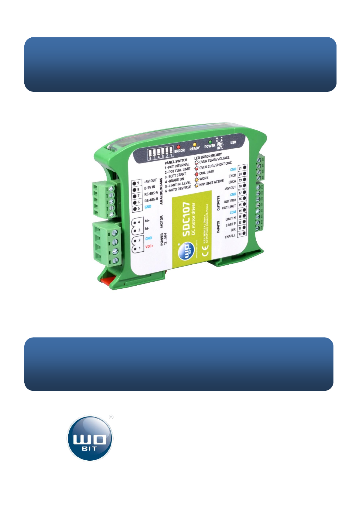
2.2 Description of connectors and indicating lamps ..........................................................................................4
2.3 Power supply ................................................................................................................................................5
2.4 Driver’s outputs ............................................................................................................................................5
2.5 Connection example.....................................................................................................................................6
2.6 Error signaling and reset...............................................................................................................................6
3. Driver configuration................................................................................................................................. 6
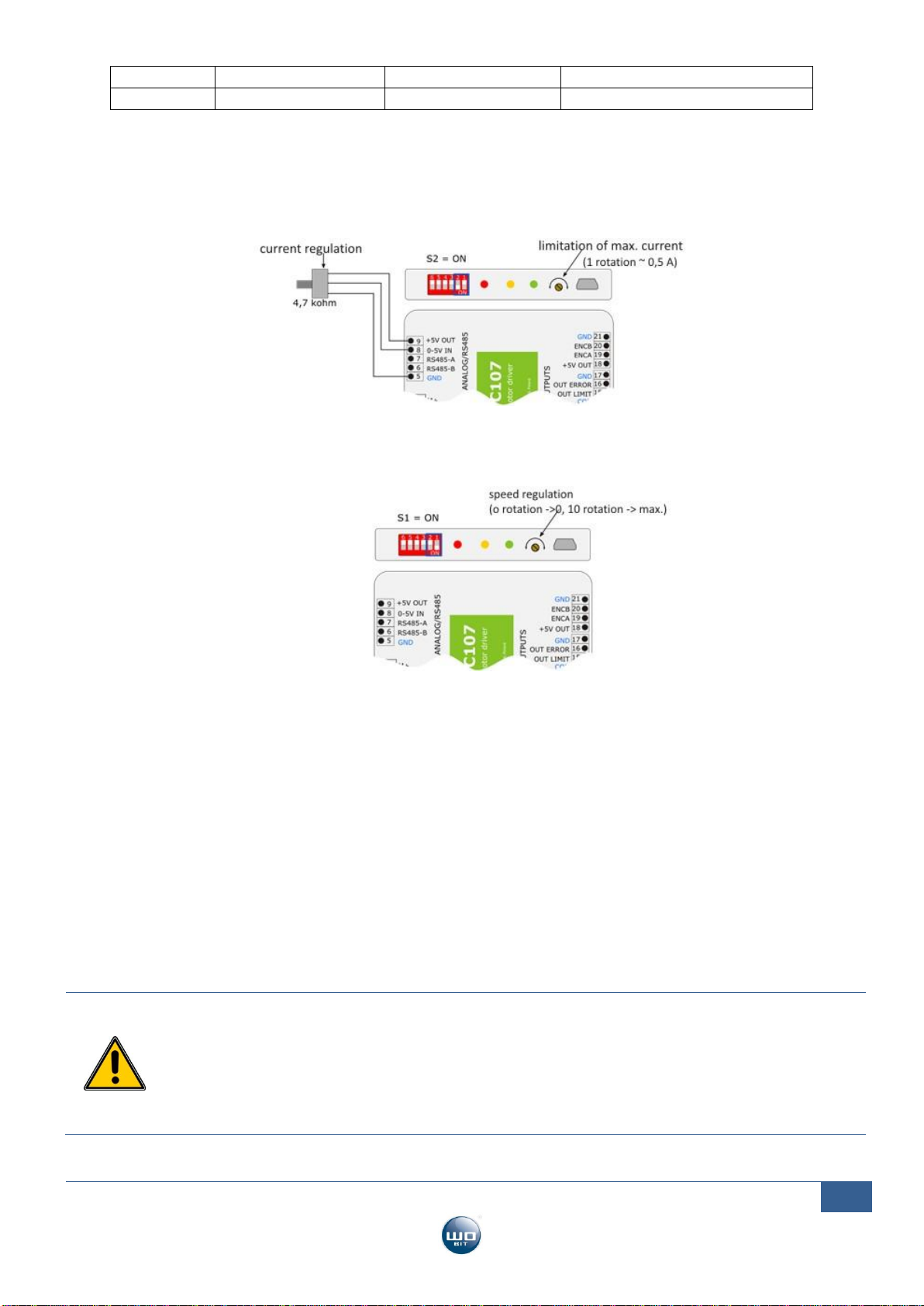
3.1 Speed/current regulation (S1/S2).................................................................................................................6
3.2 SOFT-START function (SOFT-START - S3) ......................................................................................................7
3.3 Dynamic brake function (BRAKE-STOP –S4) ................................................................................................7
3.4 Position limit inputs (LIMIT-LEVEL –S5) ......................................................................................................8
3.5 Auto-reverse function (Auto-reverse - S6) ...................................................................................................9
3.7 Driver software update.................................................................................................................................9
4Problems and solutions.......................................................................................................................... 10
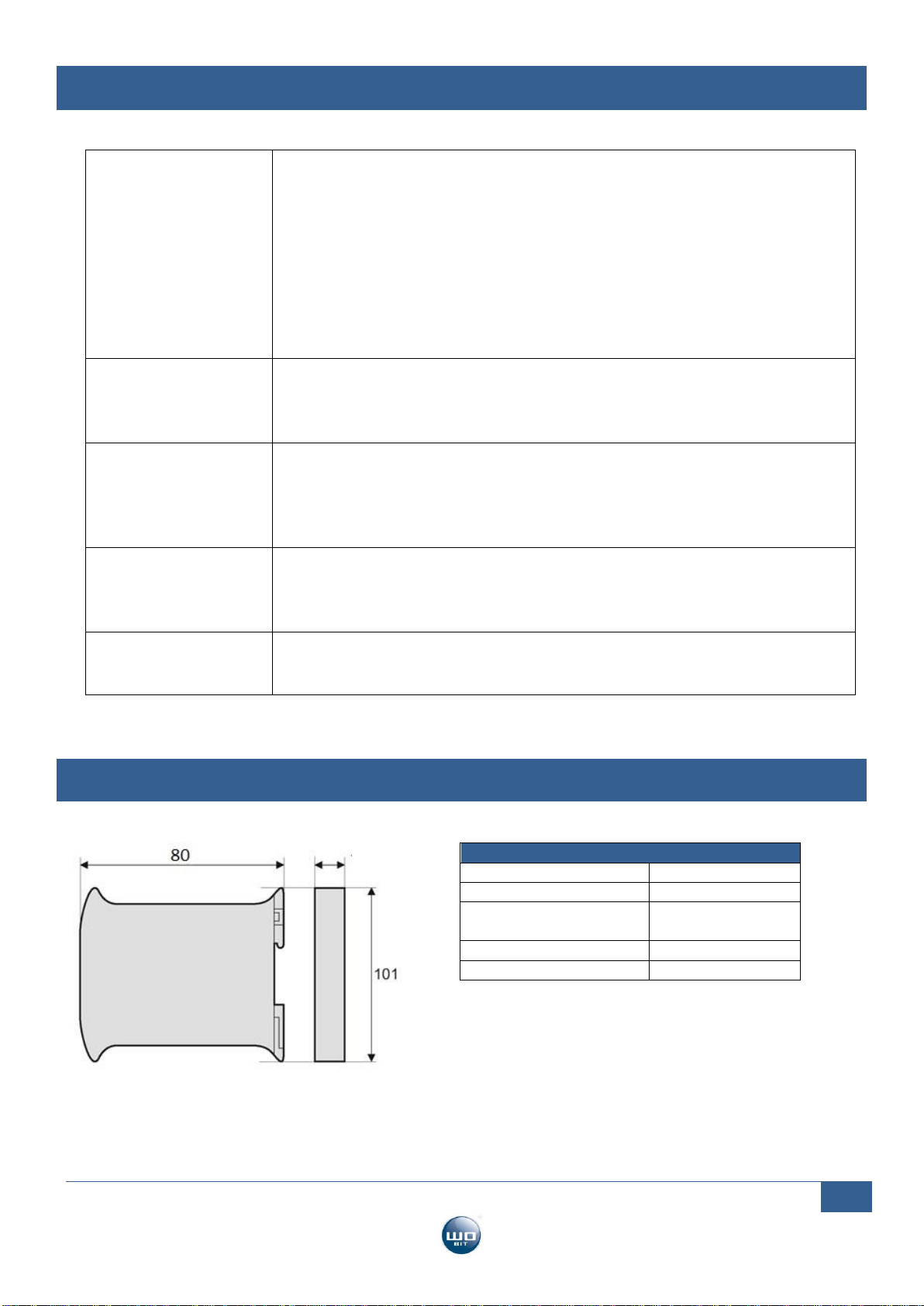
5Technical parameters............................................................................................................................. 10
Thank you for selecting our product!
This instruction will help you at correct service and accurate exploitation of described device.
Information included in this instruction were prepared with high attention by our specialists and is description of the product. Based on the
information should not be inferred a certain features or suitability for a particular application. This information does not release the user
from the obligation of own judgment and verification. P.P.H. WObit E.K.J. Ober s.c. reserves the right to make changes without prior notice.
Please read instructions below carefully and adhere to its recommendation
Please pay special attention to the following characters:
CAUTION!
Not adhere to instruction can cause damage or impede the use of hardware or software.

SDC107 –DC motor driver user manual www.wobit.com.pl
3
1. Safety and assembly rules
1.1 Safety rules
Prior to first start-up of the device please refer to this manual and keep it for further use.
Provide appropriate working conditions in compliance with the device specification ( e.g.: power supply
voltage, temperature, maximum current consumption).
Protect inside of the device from any liquids or elements –it can cause electric shock and damage of the
device.
Basic features which knowledge and use will provide safe use consonant with its designation will be
demonstrate on the device or in this manual.
The device with its parts is manufactured in way to provide its safe mounting and connection.
The device is designed and manufactured as to conform to the principles of protection against the threats
mentioned above provided that the device is used in a manner consistent with its purpose and that it is
properly maintained.
The device can cause interference of sensitive radio and television devices in nearby.
1.2 Assembly recommendation
It is recommended to follow measures described below to prevent any possible interruptions of the device
operation:
Minimize influence of external interference.
To minimize noises please use screening of the connecting cable with a motor. It is recommended to use a
ferrite bead assumed on the motor wire in close to the driver.
Please avoid leading signal cables in close to electrical and power wire of the motor; signal cables should
be possibly short.
While using servomotors powered from the same grid it should be equipped with proper power filters to
eliminate noises which can influence on driver operation. Using filters might be necessary also to eliminate
noises from the grid.

SDC107 –DC motor driver user manual www.wobit.com.pl
4
2. Device description
2.1 Intended use
SDC107 is a driver designed for DC motors with power up to about 150 W.
The driver allows, to control the motor speed and direction of rotation, and the active reduction of the maximum
current drawn by the motor (6 A).
The motor speed can be set via an external signal 0-5 V or via the built-in potentiometer.
Motor operation control (work permit, change of direction of rotation, end inputs) is carried out using optoisolated
ENABLE / DIR / LIMIT N / LIMIT P inputs.
The current limit function (regulated by an external 0-5V signal or built-in potentiometer) allows limiting the
maximum current consumed by the motor and prevent it from overheating or damage.
Features:
Continuous current up to 6 A
Voltage supply 12..36 V
Maximum current limit to prevent motor overloading
Motor speed / current regulation by an external 0-5 V signal or built-in potentiometer
Quick configuration using 6 switches on the front panel of the driver
5 V output for supplying an external potentiometer
Optoisolated inputs for the activation (ENABLE), the direction (DIR) signals and the limit (LIM N, LIMP)
2 outputs (PNP) signaling error and achieving max. current
LED indicator for power, status and error
Overcurrent and short circuit protection of power amplifiers
Thermal protection
Compact housing adapted for mounting on a DIN rail
2.2 Description of connectors and indicating lamps
Picture. 1 Description of connectors and panel.
No.
Description
Power supply
1
VDC+
Power supply 12 - 36 VDC
2
GND
Ground for power supply
3,4
M+,M-
Terminals for motor
Input 0-5V
5
GND
Ground for signals
6,7
RS485
RS485 Modbus interface (optionally)
8
0-5V
Analog signal input for speed / current regulation
9
+5V OUT
+ 5V output for powering an external potentiometer
Input
10
ENABLE
11
DIR
Input for direction select
12
LIMIT P
Input for limit switch P (for direction DIR=1)
13
LIMIT N
Input for limit switch N (for direction DIR=0)
14
COM
Ground for inputs
Outputs
15
OUT LIMIT
Output indicating a current limit
16
OUT ERROR
Error output
17
GND
Ground (common with power supply)

SDC107 –DC motor driver user manual www.wobit.com.pl
5
Signalization diodes description
POWER
Signalization of driver power supply
ERR /
CUR.LIM
Error signaling / current limitation:
flashing quickly - error (short circuit or overload)
blinking slowly - error (supply voltage / temperature exceeded)
on - the current limit set or driver max. current has been reached
READY
Motor operation signaling:
on - motor running (ENABLE = ON)
flashing - end limit input active (ENABLE = ON and active LIMIT Nor P*)
*active limit = high state at LIMIT input for switch LIMIT-LEVEL = OFF, or low state for switch
LIMIT-LEVEL = ON
Switches description
S1
POT-INT
Activation of speed control from the internal potentiometer
S2
POT-MODE
Current limit mode
S3
SOFT-START
Soft start function
S4
BRAKE-STOP
Braking function in the absence of ENABLE signal and limit signals
S5
LIMIT-LEVEL
Change of polarization of limit sensor inputs (S5 ON - limit switch active in
low state)
S6
AUTO-REVERSE
Automatic change of direction of rotation of the motor when reaching the
limit sensor.
2.3 Power supply
Driver power supply
To power the driver, it is recommended to use a power supply with an output voltage equal to the rated voltage of
the motor used (in the range of + 12 ... + 36 V) and current capacity appropriate to the motor power. In the case of
larger motors, the power supply should allow receiving reverse energy from the driver, which is why it is not
recommended to use stabilized power supplies, or it should be equipped with additional capacitors at the output
with a capacity of min. 4700 uF.
Output +5V OUT
Driver facilitate +5 V voltage which can be used for supplying of external potentiometer connected 0-5 V IN input.
Maximal current consumption for all +5 V outputs can’t exceed 100 mA.
CAUTION!
Clenching +5 V OUT output with ground (GND) or with power supply (VDC+) can cause damage of the driver.
2.4 Driver’s outputs
The driver has two PNP OC type outputs with max. 40 mA load. An active output causes the appearance of a VDC
supply voltage.
OUT OUT ERROR output - active in the event of a driver error
OUT LIMIT output - active when the motor reaches the set current limit. It can be used e.g. to signal
mechanical blocking of the motor, etc.
CAUTION!
The outputs are not suitable for supplying actuators (electromagnets, contactors, etc.). They are intended as
diagnostic information for a superior control system (e.g. PLC).

SDC107 –DC motor driver user manual www.wobit.com.pl
6
2.5 Connection example
Picture. 2 Basic signal connection.
2.6 Error signaling and reset
The driver can signal following errors:
Overload or short circuit (ERROR LED flashes quickly)
Power supply / temperature exceeded (ERROR LED flashes slowly)
In the event of an error, the motor is turned off, the ERROR LED flashes and the OUT ERR output passes high.
To reset the error and continue the driver operation, remove and provide the ENABLE signal again.
3. Driver configuration
The device is configured using the switches on the front panel.
S1
POT-INT
Activation of speed control from the internal potentiometer
S2
POT-MODE
Current limit mode
S3
SOFT-START
Soft start function
S4
BRAKE-STOP
Braking function in the absence of ENABLE signal and limit signals
S5
LIMIT-LEVEL
Change of polarization of limit sensor inputs (S5 ON - limit switch active in
low state)
S6
AUTO-REVERSE
Automatic change of direction of rotation of the motor when reaching the
limit sensor.
3.1 Speed/current regulation (S1/S2)
The maximum speed and current of the motor are regulated using an external 0-5 V voltage supplied to the 0-5 V
IN input and a built-in 10-turn potentiometer.
Depends on S1 and S2 switches settings following combinations are possible:
S1 (POT-IN)
S2( POT-CUR-MODE)
Function of 0-5V input
Potentiometer function
OFF
OFF
Speed control
--- *
ON
OFF
--- *
Speed control

SDC107 –DC motor driver user manual www.wobit.com.pl
7
OFF
ON
Speed control
Current limitation
ON
ON
Current limitation
Speed control
In cases of using the built-in 10-turn potentiometer to set the desired current:
turn the potentiometer maximally to the left (make 10 turns or until you feel resistance)
turn the potentiometer clockwise X times 0.5 A (e.g. for 2 A current turn 4 turns).
A) Example: Speed regulation by an external potentiometer and current limitation using built-in
Picture. 3 Speed regulation by external potentiometer with current limitation.
B) Example: Speed control with built-in potentiometer without current limitation max. (~ 6 A)
Picture. 4 Speed control with built-in potentiometer.
3.2 SOFT-START function (SOFT-START - S3)
The S3 switch enables activation of the SOFT-START function, which causes a soft start of the motor (the delay in
reaching the maximum speed is about 2 seconds).
Activation of the function may be necessary when controlling motors with more power or driving mechanisms with
greater inertia. Otherwise, the driver may indicate overload during the start or reversing at a higher speed.
3.3 Dynamic brake function (BRAKE-STOP – S4)
Switching S4 to ON enables the dynamic braking function. Then, removing the ENABLE signal or giving a signal to
the limit input (LIMIT N or P) causes the motor to stop abruptly. During such braking, the energy from the motor is
returned by the driver to the power source.
CAUTION!
During dynamic braking, the energy of the accelerated motor is returned by the driver in the form
of voltage to the power source (the motor then works as a generator). Therefore, it is necessary to
provide power supply to the driver to collect reverse energy - e.g. equip the power supply with large
electrolytic capacitors. Therefore, the use of switched-mode power supplies is also not
recommended.

SDC107 –DC motor driver user manual www.wobit.com.pl
8
3.4 Position limit inputs (LIMIT-LEVEL – S5)
The driver has two inputs (LIMIT-L and LIMIT-P) allowing the motor to stop after activation of the input depending
on the current motor direction (DIR input).
Direction
DIR input
Input
LIMIT-L
Input
LIMIT-R
Operation status
OFF
Active
…
Stopped
OFF
Inactive
…
Operating
ON
…
Active
Stopped
ON
…
Inactive
Operating
The S5 switch determines the type of limit sensors used. When S5 = OFF it is for NO (Normal Open) sensors, when
S5 = ON it is NC (Normal Close) sensors.
For 3-wire applications (e.g. inductive), use sensors with PNP output. When using sensors with NPN output, the
LIMIT N / P input should be pulled up to + VDC with a 2.2k ohm resistor, taking into account the reverse logic of
the sensors.
A) Example of connecting the driver to the motor driving the screw with limited movement in two
directions with NO type sensors
Picture. 5 Connection sensors NO type.
B) Example of connecting the driver to the motor driving the screw with limited movement in two
directions with NC type sensors
Picture. 6 Connection sensors NC type.

SDC107 –DC motor driver user manual www.wobit.com.pl
9
C) Using the LIMIT N / P inputs as an input to stop motor operation
Picture. 7 Using LIMIT N/P inputs as "STOP" input.
3.5 Auto-reverse function (Auto-reverse - S6)
Turning on the Auto-reverse function (switch S6 = ON) automatically changes the direction of rotation of the motor
when the limit switch is activated.
Auto-Reverse function operation:
Starting the motor operation requires signal input to ENABLE.
The motor moves in the direction depending on the signal at the DIR input.
After reaching the extreme position and activating the LIMIT N or P sensor, the motor stops for about 3
seconds.
After the time elapses, the motor moves in the opposite direction until the second LIMIT sensor is
activated and the motor stops for 3 seconds. The sequence is repeated.
3.7 Driver software update
Putting all switches in the ON position and turning on the driver power supply causes its activation in the software
update mode (via USB). Configuration S1..S6 = ON is therefore not allowed during normal operation of the driver.

SDC107 –DC motor driver user manual www.wobit.com.pl
10
4Problems and solutions
The motor does not
revolve
1) Check if the green POWER LED is on. If not - no power supply to the driver or
damaged driver.
2) Check if a signal is given to the ENABLE input.
3) Check if the LIMIT LED is flashing. If so, it means that the limit input is active
(chapter 3.4)
4) Check if the red ERR LED is flashing. If so, it means the driver is
in error mode. To clear the error, remove and re-enter the ENABLE signal.
5) Check the configuration of the S1 / S2 switches (chapter 3.1).
6) If external control is active, check that the control voltage has been applied
(0..5 V).
The driver signals an
error after changing the
direction of rotation or
switching on.
The motor starting current is too high. The driver signals when the max current is
reached or goes into error mode (the ERROR LED flashes). It is recommended to
enable the SOFT-START function (switch S3 = ON).
The driver signals an
error during braking.
For the active BRAKE-STOP S4 = ON mode, braking returns energy from the
motor to the power supply, which may increase the power supply voltage. If the
power supply is not able to receive such energy (too small electrolytic capacitors
at the power output), the driver supply voltage may exceed the max. value (40
V). Then the driver will go into error condition.
The driver signals an
error as soon as the
ENABLE signal is
activated.
Check for a short circuit between motor leads or between the M + or M- signal
and GND or VDC.
If the error repeats and cannot be cleared, the driver has been damaged.
The motor is spinning
slowly, the red LED is
on.
The motor current limit is active. Check the configuration of the S1 switches
and S2 and depending on the set mode, increase the current limit with the built-
in potentiometer or an external 0-5V signal.
5Technical parameters
Mechanical parameters
Housing dimensions:
101 x 18 x 80 mm
Weight: approx.
100 g
Operating temperature
range:
5..50 °C
Protection degree:
IP20
Mounting
DIN rail
18

SDC107 –DC motor driver user manual www.wobit.com.pl
11
Electrical parameters
Power supply VDC+
12…36 VDC
Current consumption
Motor turned off: 50 mA
Output +5 V
5 V, max. current consumption 100 mA.
Max. Motor constant current
6 A
Analog input 0-5 V IN
0-5 V, input resistance 4,4k ohm.
Control inputs ENABLE, DIR, LIMIT
N, LIMIT P
Optoinsulated, low level <2 V, high level >
5 V (max. 36 V)
Outputs OUT ERR, OUT LIMIT
Transistor PNP (source), max. 50 mA
PWM frequency of the power stage
20 kHz
Operating temperature range
0…+50 o C
Table of contents
Other WOBIT DC Drive manuals
Popular DC Drive manuals by other brands

Siemens
Siemens SIMOVERT FC operating instructions

Superior Electric
Superior Electric SLO-SYN SS2000MD4-M installation instructions

ABB
ABB DCS880 series Hardware manual

Danfoss
Danfoss VLT AQUA Drive FC 202 Programming guide

ECG
ECG M335 user manual

Bosch
Bosch Rexroth Sytronix SvP 7020 PFC operating instructions