Bentel Security FC490ST User manual

ITALIANO
SPECIFICHE TECNICHE
MECCANICHE:
Dimensioni:
HLP:48 x 200 x 112 mm
Peso
FC490ST Strumento program-
mazione dispositivi indirizzabili:0,36 Kg
FC490ST Strumento program-
mazione dispositivi indirizzabili +
batterie: 0,5 Kg
Materiali:
Superiore:
Inferiore:
FR ABS Nero e blu
FR ABS Nero e blu
ELETTRICHE:
L'art.FC490ST può funzionare con l'illuminazione LCD OFF o ON.
Batterie: 4 x ricaricabili AA al Nickel Metal
Hydride
Tempo di funzionamento (solo
Batterie): Sopra le 15 ore (dipende dalla carica
e dalle modalità d'uso delle batterie)
L'adattatore ac è richiesto quando i dispositivi indirizzabili sono ad
alta corrente, incluso l'FC430SAM/SAB.
CARATTERISTICHE AMBIENTALI
Temperatura di funzionamento da 0°C a +45°C
Temperatura di stoccaggio: da 0°C a +50°C
Umidità relativa: 90% (senza condensa)
Smaltimento batteria: Non ci sono speciali considerazio-
ni applicabili . ( Da verificare con
le autorità locali)
EMC
Lo strumento di programmazione FC490ST è conforme ai requisiti
EU EMC Direttiva 89/336/.
ENGLISH
TECHNICAL SPECIFICATION
MECHANICAL
Dimensions
HWD:48 x 200 x 112 mm
Weight
FC490ST Loop Service
Tool:0.36 Kg
FC490ST Loop Service
Tool + batteries: 0.5 Kg
Materials:
Top:
Bottom:
FR ABS Dark Blue
FR ABS Dark Blue
ELECTRICAL
The FC490ST can be operated with LCD backlight OFF or ON.
Batteries: 4 x rechargeable AA size Nickel Metal
Hydride
Operating Time (Batteries
only) Up to 15 hours (dependent on battery
charge and usage)
The ac adaptor is required when testing high current addressable
devices, including the FC430SAM/SAB.
ENVIRONMENTAL
Operating Temperature: 0°C to +45°C
Storage Temperature: 0°C to +50°C
Relative Humidity: 90% (non-condensing)
Battery Disposal: No special considerations are appli-
cable in the UK at time of writing.
(Check with local authorities).
EMC
The FC490ST Loop Service Tool meets the requirements of the
EU EMC Directive 89/336/.
Strumento programmazione dispositivi indirizzabili FC490ST FIG. 1FC490ST Loop Service Tool
FC490ST
®
ISO 14001
9191.BNT2
ISO 14001
IT-52588
ISO 9001
9105.BNT1
ISO 9001
IT-52587
STRUMENTO PROGRAMMAZIONE DISPOSITIVI INDIRIZZABILI
LOOP SERVICE TOOL
ISTPTBL3FC490ST 1.0 070108

2FC490ST
INTRODUCTION
The FC490ST Loop Service Tool is used to program the loop ad-
dress into FC addressable devices. (A quick Functional Refer-
ence table is detailed on page 11). The FC490ST displays
information and performs tests on devices.It has a 32 character
backlit LCD alphanumeric display, arranged in 2 rows of 16 char-
acters and four ‘softkeys’, F1, F2, F3 and F4 (The display format
is shown in Fig. 3). Power for the FC490ST is derived from 4 AA
size nickel metal hydride rechargeable batteries. It may be run
from an unregulated +12V dc input ie, car cigarette lighter con-
nection or 110/230V ac mains adaptor, both of which will re-
charge the batteries as well. The FC490ST consists of the
following:
ØLoop Service Tool
ØService Tool to ancillary connector lead
Ø110 or 230V ac adaptor plus lead
Ø4 x rechargeable AA size Nickel Metal Hydride batteries
The FC490ST is designed to be used as a desktop unit, clipped to
a trouser belt or be carried with a shoulder strap. The FC490ST
has four external connections:
DC IN +12V From car cigarette lighter or
110/230V ac mains adaptor
AUX Ancillary connection port
PC
PC connection port for use
with MX CONSYS (not yet
available)
µP Not used
Detectors are programmed by placing the detector onto the
FC490ST and turning clockwise until fully engaged.
Ancillaries are programmed via the AUX port on the FC490ST.
The ancillary programming cable consists of an RJ11 connector at
one end and a custom moulded connector at the other end.
OPERATION
!IMPORTANT:
•FULLY CHARGE THE BATTERIES FOR 10 HOURS
BEFORE USING FOR THE FIRST TIME.
•RECHARGE THE BATTERIES AS SOON AS THE LOW
BATTERY INDICATOR APPEARS.
•DO NOT OPEN BATTERY LID WHILE THE UNIT IS
SWITCHED ON.
STARTING UP
INSTALLING BATTERIES
To install/change the batteries, proceed as follows:
1) Unscrew the two screws on the base of the FC490ST, using a
cross-point screwdriver, holding the battery compartment
cover whilst removing it.
2) Insert the batteries ensuring correct polarity as shown inside
the battery compartment.
INTRODUZIONE
Lo strumento di programmazione FC490ST è progettato per la pro-
grammazione dei dispositivi indirizzabili della serie FC. ( Una tabella
con le specifiche di funzionamento è visibile a pagina 11). Sul display
dello strumento di programmazione FC490ST compaiono le informa-
zioni delle specifiche di test e delle apparecchiature. Il display è compo-
sto da un pannello LCD retroilluminato alfanumerico da 32 caratteri
organizzato in 2 file da 16 caratteri e da quattro ‘tasti funzione’,F1,F2,F3
e F4 (Il formato del display è visibile in Fig.3). L'alimentazione dello stru-
mento di programmazione FC490ST è fornita da 4 batterie AA al nickel
metal hydride ricaricabili. Può anche funzionare con tensione non stabi-
lizzata di +12 Vdc, fornibile tramite l'accendisigari dell'autovettura o tra-
mite un alimentatore 110/230 Vac, entrambi possono ricaricare, se
inserite, le batterie. L'articolo FC490ST è composto da:
ØStrumento per la programmazione dei dispositivi indirizzabili.
ØCavo per moduli da utilizzare con lo strumento per la programmazione.
ØAlimentatore 110 o 230 Vac con cavo.
Ø4 batterie ricaricabili AA al Nickel Metal Hydride
L'art. FC490ST è progettato per essere usato appoggiato sopra un ta-
volo, agganciato alla borsa da lavoro oppure trasportato a spalla con
una cinghia. L'art. FC490ST possiede quattro connessioni esterne:
DC IN +12V Presa per accendisigari auto
o alimentatore 110/230 Vac
AUX Porta per cavo moduli
PC
Porta di connessione PC o uso
con FireClass 500 Console
(non ancora disponibile)
µP Non usato
Per programmare i rilevatori applicare il rilevatore sopra l'art.
FC490ST e girare in senso orario fino al completo aggancio.
I moduli vanno programmati tramite il connettore AUX dell'art. FC490ST.
Il cavetto di programmazione moduli è composto su una estremità da
un connettore RJ11e sull'altra estremità da un connettore realizzato
secondo specifiche.
OPERAZIONI
!IMPORTANTE:
•METTERE SOTTO CARICA LE BATTERIE PER 10 ORE
PRIMA DEL LORO PRIMO UTILIZZO.
•RICARICARE LE BATTERIE APPENA COMPARE
L'INDICATORE DI CARICA BASSA.
•NON APRIRE IL COPERCHIO DELLE BATTERIE MENTRE
L'APPARECCHIATURA E ACCESA.
AVVIAMENTO
INSTALLAZIONE BATTERIE
Per inserire e sostituire le batterie, procedere come segue:
1)Svitare le due viti sulla base dell'art. FC490ST usando un cac-
ciavite a croce, prima di rimuovere il coperchio tenere il com-
partimento di alloggiamento delle batterie.
2)Inserire le batterie rispettando la corretta polarità, come indi-
cato all'interno dell'alloggiamento batteria.

FC490ST 3
3)Rimettere il coperchio dell'alloggiamento batteria e le viti.
!ATTENZIONE: ASSICURARSI CHE LE BATTERIE
RICARICABILI NICKEL METAL HYDRIDE, PRIMA
DELL'USO, SIANO COMPLETAMENTE CARICHE.
CARICAMENTO ED UTILIZZO
L'art. FC490ST possiede un circuito interno di carica alimentato
dall'alimentatore esterno. Le batterie possono avere una carica
breve intorno alle 4-5 ore, ma raggiungono la carica completa in
10 ore. L'art. FC490ST può essere alimentato direttamente dalla
linea principale usando l'alimentatore ac. Se le batterie sono in-
stallate,l'alimentazione esterna permette contemporaneamente la
ricarica. Per l'indicatore batteria bassa, vedere pagina 9.
PASSWORD DI PROTEZIONE
Lo strumento di programmazione per dispositivi indirizzabili FC490ST
può essere commutato in ON/OFF premendo qualunque tasto per un
tempo superiore ai 3 secondi. Il seguente schermo di esempio mostra il
numero di revisione del software ed è visualizzato per 2 secondi quan-
do lo strumento di programmazione viene acceso:
MX SERVICE TOOL
Rev 1.00.1806E
Da notare che sul display è impostata la lingua inglese 'E' ( una let-
tera diversa è usata per altre lingue ). Di seguito sul display dello
strumento compare il messaggio sotto evidenziato:
Password:
+Note: Le seguenti informazioni sulla password di protezione sono
FONDAMENTALI per le operazioni con lo strumento di program-
mazione.
Lo strumento di programmazione richiede una password di 6 ca-
ratteri per accedere. La password di accesso utilizza solo le cifre
da 1 a 4 e può essere inserita premendo i tasti corrispondenti da
F1 a F4,esempio; tasto F1 per inserire 1, tasto F2 per inserire 2,
ecc. La password è 121234.
!ATTENZIONE: L'INSERIMENTO DELLA PASSWORD
D'ACCESSO NON CORRETTA, AL QUARTO TENTATIVO,
PROVOCHERƒ LO SPEGNIMENTO DELLO STRUMENTO DI
PROGRAMMAZIONE PERMETTENDO SOLO UNA
SUCCESSIVA RIACCENSIONE DELL'UNITƒ.
Quando la password inserita è corretta, viene visualizzato il menù principale.
COLLEGAMENTO DEL DISPOSITIVO
Usare il riferimento sullo strumento di programmazione (sopra il
tasto F1) per allineare il rilevatore. Ruotare il rilevatore in senso
orario per agganciarlo . I moduli vanno collegati alla porta ‘AUX’
usando il cavo di connessione apposito .
3) Replace the battery compartment cover and screw down.
!CAUTION: ENSURE ONLY NICKEL METAL HYDRIDE
RECHARGEABLE BATTERIES ARE USED AND FULLY
CHARGED BEFORE USE.
CHARGING AND MAINS USE
The FC490ST has its own built-in charging circuit powered by the
mains adaptor. The batteries are boost-charged for 4-5 hours and
reach full charge within 10 hours. The FC490ST can be powered
from the mains supply using the ac adaptor. If batteries are in-
stalled, this allows them to be charged at the same time. For low
battery indicator, see page 9.
PASSWORD PROTECTION
The FC490ST Loop Service Tool is switched ON/OFF by pressing
any button for more than 3 seconds. The following example
screen showing the software revision number, is displayed for 2
seconds when the Service Tool is switched on:
MX SERVICE TOOL
Rev 1.00.1806E
Note that the ‘E’ displayed stands for English version (appropriate
letters are used for other languages). The ServiceTool then dis-
plays the screen below:
Password:
+Note: The following information on Password Protection is
CRUCIAL to the operation of the ServiceTool.
The Service Tool requires a 6-digit password to be entered. The
password uses only the digits 1 to 4, and may be entered by press-
ing the corresponding buttons F1 to F4; eg, button F1 to enter 1,
button F2 to enter 2, etc. The password is 121234.
!WARNING: FAILURE TO ENTER THE CORRECT
PASSWORD AT THE FOURTH ATTEMPT WILL RESULT IN
THE SERVICE TOOL SWITCHING OFF AND ALLOWING
ONLY ONE ATTEMPT ON SUBSEQUENT POWERING UP
OF THE UNIT.
On successful entry of the password, the main menu is displayed.
CONNECTING TO A DEVICE
Use the marking on the service tool (above F1 button) to align the
detector. Rotate the detector clockwise to engage. Ancillaries are
connected to the ‘AUX’ socket using the ancillary connection lead.
4FC490ST
+Note:
1) It is good practice to connect either a detector or ancillary at
any one time. However, the Service Tool is equipped with a
port interlock feature. When the ancillary lead is connected to
the ‘Aux’ socket,communication with the detector will be dis-
abled. When the ancillary lead is removed, the detector will be
able to communicate.
2) The FC490ST may be connected to an ancillary device that is
also connected to and powered from the addressable
loop.However, a ‘No Response’ fault for that device may be
generated at the Control Panel under these conditions.
!WARNING: SPECIAL CARE MUST BE TAKEN WHEN
CONNECTING TO A DEVICE ON THE ADDRESSABLE
LOOP TO PREVENT UNWANTED ACTION IN OTHER
EQUIPMENT EG, EXTINGUISHING SYSTEMS.
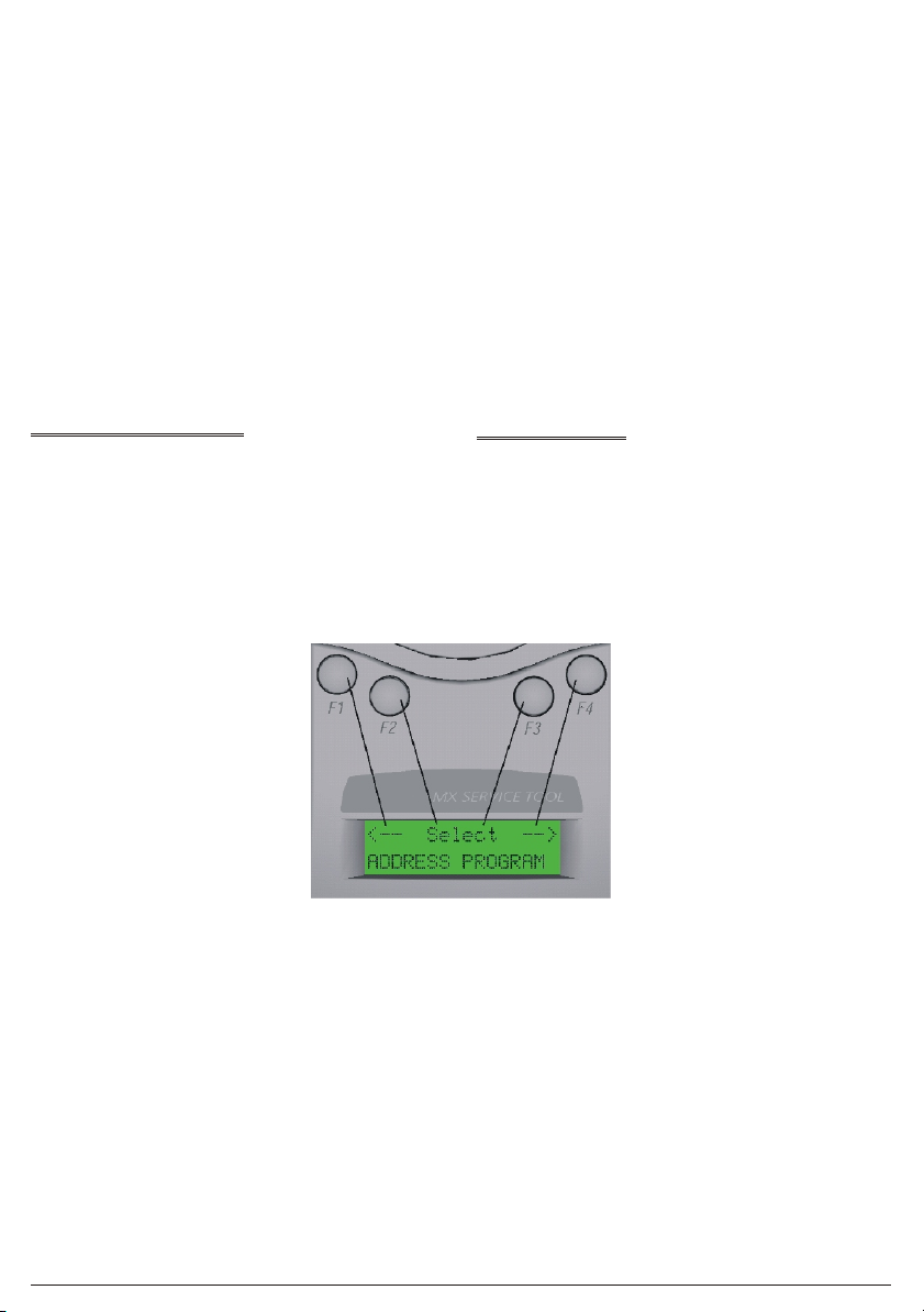
BUTTON OPERATION
The screen displays the start of the main menu as shown in Fig. 2.
The main menu can always be identified by the word ‘Select’ bet-
ween two arrows on the top line of the display. The bottom line
of the main menu displays the option. The top line position of text
is always shown in relation to the F1-F4 buttons above.In the Main
Menu:
ØF1 scrolls left through the main menu options
ØF2 or F3 select the menu option displayed
ØF4 scrolls right through the main menu options
When an option is selected from the main menu, the display uses
the format shown in Fig. 3:
The bottom line displays information to the user. The top line dis-
plays the available options.
+Note:The position of the options on the top line is relative to the
buttons.
Fig. 3 shows:
+Note:
1)‹buona norma collegare solo un rilevatore oppure solo un modu-
lo. Comunque si proceda, lo strumento di programmazione è
equipaggiato da un dispositivo di blocco. Quando il cavo moduli è
collegato alla porta ‘AUX’, la comunicazione con il rilevatore è di-
sabilitata. Quando il cavo moduli è scollegato, la comunicazione
con il rilevatore è abilitata.
2)L'art. FC490ST può essere collegato ad un modulo esterno
connesso e alimentato dal loop indirizzabile.Tuttavia, in queste
situazioni, la Centrale di Controllo può segnalare un ‘No Re-
sponse’ difetto per quel dispositivo.
!ATTENZIONE: SPECIALI PRECAUZIONI DEVONO ESSERE
PRESE QUANDO SI COLLEGA LO STRUMENTO AL LOOP
INDIRIZZABILE PER IMPEDIRE AZIONI INDESIDERATE IN
ALTRE APPARECCHIATURE PER ESEMPIO, LA
DISABILITAZIONE DEI SISTEMI DI ESTINZIONE.
FUNZIONAMENTO DEL TASTO
Lo schermo del display all'avvio del menù principale è visibile in Fig.2.
Il menù principale può essere sempre identificato dalla parola
‘Select’ inserita tra due frecce sulla linea superiore del display.
La linea inferiore del menù principale del display visualizza l'op-
zione. La posizione della linea superiore di testo è indicata sem-
pre rispetto ai tasti F1-F4 qui sopra. Nel menù principale:
ØF1 per scorrere a sinistra le opzioni del menù principale
ØF2 o F3 per selezionare l'opzione sul menù visualizzato
ØF4 per scorrere a destra le opzioni del menù principale
Quando un'opzione è selezionata dal menù principale, il display si
presenta come visibile in Fig. 3:
La linea inferiore del display riporta le informazioni utente. La li-
nea superiore del display le opzioni disponibili.
+Annotazioni: La posizione delle opzioni sulla linea superiore è
in relazione ai tasti.
Vedere Fig. 3:
Display prima videata del menù principale FIG.2First Display Screen of the main menu

FC490ST 5
F1 Selecting ‘Back’
F2 Selecting ‘Write’
F3 Selecting ‘Dn’ (for down)
F4 Selecting ‘Up’
In some cases there may be fewer options available.
Fig. 4 shows:
F1 Selecting ‘Menu’
F2 Selecting ‘Write’
F3 No action
F4 Clear used memory map
In Fig. 5 pressing F1 selects the ‘Menu’, F2-F4 are redundant
here.
FUNCTIONALITY
ADDRESS PROGRAM
<-- Select -->
ADDRESS PROGRAM
F1 Seleziona ‘Back’
F2 Seleziona ‘Write’
F3 Seleziona ‘Dn’(per giù)
F4 Seleziona ‘Up’
In alcuni casi ci possono essere poche opzioni disponibili.
Vedere Fig.4:
F1 Seleziona ‘Menu’
F2 Seleziona ‘Write’
F3 Nessuna azione
F4 Cancella programma usato in
memoria
In Fig.5 premere F1 per selezionare il ‘Menu’, F2-F4 qui sono non
attivi.
FUNZIONAMENTO
PROGRAMMAZIONE INDIRIZZO
<-- Select -->
ADDRESS PROGRAM
Esempio di scrittura indirizzo FIG.3Example of Writing an address
Esempio di lettura dell'indirizzo FIG.4Example of Reading an address

6FC490ST
The main menu starts with ADDRESS PROGRAM. Press buttons
F2 or F3 to choose ‘Select’ and the address of the device is dis-
played ( eg, address 4 ).
Menu Write CIU
ADDRESS:4
ØUse ‘Write’ to program the device with a new address
Ø‘Menu’ to return to the main menu
Ø‘ClU’ to clear the memory map of used addresses
+Note:Whenever ‘Menu’ appears on the display, this always re-
turns to the main menu.
The Service Tool stores a memory map of the addresses that
have been programmed. To erase this, select the ‘ADDRESS
PROGRAM’ menu and choose Clear Used ‘ClU’.
If ‘Write’ is selected, the following screen is displayed:
Back Write Dn Up
ADD:4
ØUse ‘Up’ to increase the address number
Ø‘Dn’ to decrease it
Ø‘Write’ to program the address displayed
Ø‘Back’ to return to the previous screen
If ‘Write’ is selected then the following message will appear for 2
seconds:
Back Write Dn Up
PROGRAMMED OK
This is followed by:
Back Write Dn Up
ADD:5
Having programmed an address, the Service Tool moves to the
next unused sequential address.
If the user selects an address that has already been used, the Ser-
vice Tool indicates:
Il menù principale si avvia con ADDRESS PROGRAM. Premere i
tasti F2 o F3 per selezionare ‘Select’ e viene visualizzato l'indiriz-
zo del dispositivo ( per esempio, indirizzo 4 ).
Menu Write CIU
ADDRESS:4
ØUsare ‘Write’ per programmare l'apparecchiatura con un nuovo indirizzo
Ø‘Menu’ per tornare al menù principale
Ø‘CIU’ per cancellare l'elenco in memoria degli indirizzi usati
+Note: Una volta che compare ‘Menu’ sul display, è possibile,
da qui ,solo tornare al menù principale.
Lo strumento di programmazione mantiene all'interno della me-
moria un elenco degli indirizzi che sono stati programmati .Per
cancellarli selezionare ‘ADDRESS PROGRAM’ dal menù e
scegliere Cancella Usato ‘CIU’.
Se si seleziona ‘Write’, viene visualizzato il seguente schermo:
Back Write Dn Up
ADD:4
ØUsare ‘Up’ per aumentare il numero di indirizzo
Ø‘Dn’ per diminuire il numero di indirizzo
Ø‘Write’ per programmare l'indirizzo visualizzato
Ø‘Back’ per tornare alla schermata precedente
Se si seleziona ‘Write’ viene visualizzato il seguente messaggio
per 2 secondi:
Back Write Dn Up
PROGRAMMED OK
Di seguito :
Back Write Dn Up
ADD:5
Programmato un indirizzo , lo strumento per la programmazione
passa sequenzialmente all'indirizzo successivo.
Se l'utente usa un indirizzo precedentemente già utilizzato, lo stru-
mento per la programmazione indica:
Esempio di Singola opzione FIG.5Example of Single Option

FC490ST 7
Back Write Dn Up
ADD:6 USED
The user has the choice to continue with a used address, or to
move to the next sequential address, using the up (Up) and down
(Dn) button.
If the user then decides to use a previously used address, the fol-
lowing screen is displayed:
Back Write
ADD.USED:6
Press ‘Write’ and the Loop Service Tool displays
‘PROGRAMMED OK’ briefly, it then displays the next available
unused sequential address.
ANALOGUE VALUES
ANALOGUE VALUES displays the analogue values of the attached device.
Menu
VAL:27 87 XX
The above example shows a device with 2 channels, eg, an Opti-
cal/Heat detector, where channel 1 is the optical value and chan-
nel 2 is the heat value. Press ‘Menu’ to return to the main menu.
+Note:
1) Only displayed if channel 3 is used on a device.
2) These are the values that the device would transmit to the con-
trol panel. The values do NOT include any calibration or cor-
rection factors.
MEASURE TEMP
This feature measures temperature in degrees Celsius and de-
grees Fahrenheit, but is only available on detectors which have a
temperature sensing element, ie, Heat only and Optical & Heat de-
tectors. A typical display is shown in b):
a)
<-- Select -->
MEASURE TEMP
b)
Menu
T: 23 C 75 F
MEASURE CO LEVEL
For CO detectors only- Not applicable to the Fireclass range of
products.
Back Write Dn Up
ADD:6 USED
L'utente può scegliere di continuare con l'indirizzo già usato , op-
pure passare sequenzialmente all'indirizzo successivo, usando i
tasti su (Up) e giù (Dn).
Se l'utente decide di usare un indirizzo precedentemente utilizzato
viene visualizzato il seguente schermo:
Back Write
ADD.USED:6
Premere ‘Write’ sul display dello strumento di programmazione e
compare ‘PROGRAMMED OK’ , immediatamente dopo viene vi-
sualizzato l'indirizzo sequenziale successivo disponibile.
VALORI ANALOGICI
ANALOGUE VALUES indica i valori del dispositivo inserito.
Menu
VAL:27 87 XX
L'esempio sopra mostra un dispositivo con 2 canali, esempio, un rilevato-
re Ottico/Temperatura, dove il canale 1 è il valore ottico ed il canale 2 è il
valore Temperatura. Premere ‘Menu’ per tornare al menù principale.
+Note:
1)Visualizzato,solo se il canale 3 è usato su un dispositivo.
2)Questi sono i valori che il dispositivo trasmette al pannello di
controllo. I valori non comprendono alcuni fattori di correzione
o di calibratura.
MISURAZIONE TEMPERATURA
Questa caratteristica misura la temperatura in gradi Centigradi ed in
gradi Fahrenheit, ma è soltanto disponibile sui rilevatori che sono dotati
di un sensore di temperatura,rilevatori solo di temperatura o ottico/tem-
peratura. Un tipico esempio è visibile in b):
a)
<-- Select -->
MEASURE TEMP
b)
Menu
T: 23 C 75 F
LIVELLO DI MISURA MONOSSIDO DI CARBONIO
Solo per i rilevatori di monossido di carbonio CO - Non è applicabi-
le ai prodotti della serie Fire Class.
CANALE 1 CANALE 2 VEDERE NOTA 1
CHANNEL 1 CHANNEL 2 SEE NOTE 1

8FC490ST
TEST ALL
This option combines a test on the detector R1 and L2 terminals
and tests the detector’s sensor circuitry for units which have this
facility.
ØThe Test R1 terminal tests the remote indicator output.
ØThe Test L2 terminal tests the functional base interface output.
ØThe Selftest tests the sensor input circuitry.Completion of the
Selftest may require a maximum of 30 seconds.
Following the completion of all three tests, a test report is dis-
played on the LCD.Each test can result in a PASS, FAIL or NOT
AVALABLE report message.
To start a new test, select the TEST ALL menu to begin.
WAIT is displayed until all tests are completed.
When the tests are complete, the test results are reported on three
alternating displays:
Menu TEST R1:
PASS
Menu TEST L2:
PASS
Menu SELFTEST:
PASS
Self Test is available only on the following type of detector:
ØFC400PH Optical + Heat (Optical sensing element only).
+Note: Self test is NOT available for the heat sensing channels
of these detectors.
DIRTINESS
Available for Optical detectors only. Indicates the contamination
level of the optical chamber.Compares the current optical ana-
logue value as a percentage where 0% would indicate that the an-
alogue value has not changed since manufacture, 100% would
indicate that the analogue value has risen to its maximum allow-
able value (the point at which it would generate a fault). At 80% or
above, the detector should be replaced to avoid the possibility of a
fault occurring in the near future.
+Note: Dirtiness can be displayed as a negative number if the
analogue value has fallen since manufacture.
Menu
DIRTINESS%:+6
DEVICE TYPE ID
Device Type ID displays the unique value associated with each
addressable device Model No., eg, for Model No. FC400PH -Type
Value 10 is displayed.
Menu
Device Type: 10
Type Value may be cross-referenced to Model No. by referring to
Table 2 on Page 11.
TEST COMPLETO
Questa opzione effettua un test sui terminali R1 ed L2 del rilevato-
re, testando i circuiti del sensore del rilevatore per le unità che
hanno questa funzione.
ØIl test sul terminale R1 esamina l'uscita per l'indicatore remoto.
ØIl test sul terminale L2 esamina l'uscita dell'interfaccia base funzionale.
ØIl test automatico verifica i circuiti d'ingresso del sensore.Un test
automatico completo può richiedere un massimo di 30 secondi.
Successivamente, al completamento di tutti e tre i test, un rapporto di
verifica viene visualizzato sullo schermo LCD. Ognuno dei test può pro-
vocare un messaggio di risposta PASS, FAIL o NOT AVALABLE.
Per avviare un nuovo test, selezionare TEST ALL sul menù.
Fino al completamento dei test il display visualizza WAIT.
Quando i test sono completati i risultati vengono visualizzati su tre
alterne schermate:
Menu TEST R1:
PASS
Menu TEST L2:
PASS
Menu SELFTEST:
PASS
Il test automatico è disponibile solo sul seguente tipo di rilevatore:
ØFC400PH Ottico + Temperatura (Soltanto sensore ottico).
+Note: Il test automatico NON è disponibile per i canali che per-
cepiscono la temperatura su questi rilevatori.
LIVELLO DI SPORCO
Disponibile solo per i rilevatori ottici. Indica il livello di contamina-
zione della camera ottica.Confronta l'equivalente del valore ottico
corrente con una percentuale, dove 0% indica che il valore di rife-
rimento non è cambiato dalla fabbricazione , mentre 100% indica
che il valore di riferimento è aumentato rispetto al valore massimo
permesso ( a questo punto si può verificare un difetto di funziona-
mento ). Sopra l'80% il rilevatore dovrebbe essere sostituito per
evitare un'eventuale difetto di funzionamento.
+Nota: Il livello di sporco può essere visualizzato come numero ne-
gativo se il valore di riferimento scende oltre quello di fabbricazione.
Menu
DIRTINESS%:+6
IDENTIFICAZIONE DISPOSITIVO
L'identificazione del dispositivo mostra un valore unico associato
ad ogni dispositivo indirizzabile, ad esempio per l'art. FC400PH il
tipo di valore visualizzato è 10.
Menu
Device Type: 10
Il valore può essere riferito all'articolo, come visibile sulla tabella 2
a pagina 11.

FC490ST 9
DIGITAL INPUTS
This menu option displays the status of the digital inputs in binary
and as a decimal number between 0 to 255 for all addressable de-
vices.The binary number is aligned with least significant bit on the
right as indicated with a small “L” character.
Menu
1110011L227
DIGITAL OUTPUTS
The user may set the Digital Output of the addressable device by
using the following function buttons:
Menu Tog --> Set
00000000L0
The flashing cursor denotes the digit to be set.
--> moves the cursor one position to the right
‘Tog’ toggles between 0 and 1 for each digit
‘Set’ sends an instruction to the addressable device
‘Menu’ to return to the main menu options
!WARNING:WHEN USING THE SERVICE TOOL ON AN
ANCILLARY DEVICE CONNECTED TO THE
ADDRESSABLE LOOP, MAKE SAFE ANY ATTACHED
EQUIPMENT, eg, EXTINGUISHING, PLANT SHUTDOWN
etc. UNLESS IT IS BEING USED SPECIFICALLY FOR
TESTING THE ATTACHED EQUIPMENT.
An LED test may be performed on addressable devices using the
digital output function. Move the cursor to the eigth bit on the
far-right and toggle this bit “1”.The LED should illuminate red on all
models.
Menu Tog --> Set
00000001L1
After ‘Set’ is selected, a message will appear asking for confirma-
tion of the action to send the data to the device, as follows:
No Yes
CONFIRM ACTION
ADDITIONAL FUNCTIONS
DEVICE POLLING
In all operations that retrieve data from an attached device, the
FC490ST polls the attached device at a pre-determined inter-
val.This interval is 2 seconds for the ADDRESS PROGRAM func-
tion and 5 seconds for all other functions.
LOW BATTERY
This is indicated by a flashing symbol in the bottom right of the
LCD display.
The batteries must be charged using the mains adaptor with its
connecting lead plugged into the Service Tool dc input (DC IN
12V) socket.
INGRESSI DIGITALI
Questa opzione sul meù visualizza la condizione degli ingressi
digitali in numero binario ed in numero decimale tra 0 e 255 per tut-
ti i dispositivi indirizzabili. Il numero binario è in linea con l'ultimo bit
significativo a destra indicato con un piccolo carattere “L”.
Menu
1110011L227
USCITE DIGITALI
L'utente può impostare l'uscita digitale del dispositivo indirizzabile
usando i seguenti tasti funzione:
Menu Tog --> Set
00000000L0
Il cursore lampeggiante indica la cifra da impostare.
--> muove il cursore di una posizione a destra
‘Tog’ Cambia il valore da 0 a 1 e viceversa
‘Set’ trasmette un istruzione al dispositivo indirizzabile
‘Menu’ per tornare alle opzioni sul menù principale
!ATTENZIONE: QUANDO SI COLLEGA LO STRUMENTO DI
PROGRAMMAZIONE AL MODULO CONNESSO AL LOOP
INDIRIZZABILE ,METTERE IN SICUREZZA TUTTE LE ALTRE
APPARECCHIATURE COLLEGATE, esempio, ESTINZIONE,
IMPIANTO D'ARRESTO ecc. A MENO CHE IL TEST RIGUARDI
PROPRIO LE APPARECCHIATURE COLLEGATE.
Una prova con il LED può essere effettuata sui dispositivi indiriz-
zabili che usano la funzione uscita digitale. Spostare il cursore
sull'ottavo bit più lontano a destra ed inserire questo bit “1”. Il LED
rosso dovrebbe illuminarsi in tutti i rilevatori.
Menu Tog --> Set
00000001L1
Dopo aver selezionato ‘Set’, compare un messaggio per la confer-
ma dell'azione di trasmissione dati al dispositivo, come segue:
No Yes
CONFIRM ACTION
FUNZIONI SUPPLEMENTARI
SONDAGGIO DISPOSITIVO
In tutte le operazioni che richiedono dei dati al dispositivo collegato,
l'art. FC490ST comunica con il dispositivo collegato con un intervallo
predeterminato. Questo intervallo è di 2 secondi per la funzione
ADDRESS PROGRAM e di 5 secondi per tutte le altre funzioni.
BATTERIA BASSA
Questo è indicato da un simbolo lampeggiante in fondo a destra
sul display LCD.
Le batterie devono essere caricate usando l'alimentatore con il relativo
cavo inserito sull'ingresso dc (DC IN 12V) dello strumento di program-
mazione.

10 FC490ST
LCD BACKLIGHT
The display can be temporarily illuminated by pressing any two
buttons simultaneously at any time.
AUTO POWER OFF
AUTO POWER OFF is designed to save battery life. If there have-
been no button presses during the last 5 minutes, the Service Tool
automatically turns it self off.
CPU RESET
+Note:This function is not normally used.
If the buttons or display are not responding correctly, the Service
Tool may be reset. This is done by pushing a small jewellers type
screwdriver into the pinhole on the bottom of the Loop ServiceTool
to actuate a switch.
When a CPU reset is carried out, the Service Tool will start up as
described in ‘Password Protection’.
ACCESSORIES
ACCESSORY KIT
Consisting of:
wCarry case
wCar charger
wShoulder strap
SPARES
Spare ancillary lead:
Ancillary lead spare pins (bag of 10):
ILLUMINAZIONE LCD
Il display può essere temporaneamente illuminato premendo allo
stesso tempo due tasti qualsiasi.
AUTO SPEGNIMENTO
L'auto spegnimento è progettato per preservare la durata delle
batterie. Se non viene premuto un tasto negli ultimi 5 minuti, lo
strumento di programmazione si spegne automaticamente.
RESET CPU
+Nota: Questa funzione non è normalmente usata.
Se i tasti o il display non rispondono correttamente, lo strumento di pro-
grammazione può essere resettato. Questo può essere fatto spingendo
un piccolo cacciavite all'interno di un foro di spillo situato sulla parte infe-
riore dello strumento di programmazione, attivando così un interruttore.
Quando la CPU viene resettata , lo strumento per la programmazione vi-
sualizza all'avvio ‘Password Protection’.
ACCESSORI
KIT ACCESSORI
Consiste in:
wCustodia da trasporto
wAlimentatore per auto
wCinghia a tracolla
RICAMBI
Cavo di ricambio.
Perni di ricambio ( confezioni da 10 ).

FC490ST 11
MENU FUNCTIONS
ØTable 1: Functional Reference Table
MAIN MENU
DISPLAY ACTIONS
‘Address Program’
•Read/Writes the address of the
connected addressable device
•Reads the stored address map of
used addresses
‘Analogue Values’ •Displays the analogue values of the
addressable device
‘Measure Temp.’
•Measures temperature in degrees
C and F (only available on detectors
which have a temperature sensing
element)
‘Test’ All
Performs:
•a self test, if the detector has such a
facility
•remote LED output
•functional base interface output
‘Dirtiness’
•Indicates the contamination level of the
optical chamber expressed as a
percentage, where 100% is the fault level
Device Type ID’ •Displays the device type
identification value
‘Digital Inputs’ •Displays the status of the digital
inputs in addressable devices
‘Digital Outputs’ •Allows the user to set the digital
output of the addressable device
Low Battery
•Indicates Low Battery by using a
flashing symbol in the bottom right
of the LCD display
CPU Reset
•Switch is accessed through a small
hole at the rear of the unit near the
label
LCD Backlight
•The display can also be temporarily
illuminated by pressing any two
buttons simultaneously at any time
ØTable 2: Type Values
DESCRIPTION MODEL TYPE
VALUE
Optical Smoke/Heat
Detector FC400PH 10
Optical Smoke Detector FC400P 15
Heat Detector FC400H 20
Sounder module FC430SAM 80
Loop
Powered Beacon FC430SAB 82
Mini-Input Module FC410MIM 128
Indoor callpoint FC420CP 129
Outdoor callpoint FC421CP 130
Single I/O module FC410SIO 148
Multi I/O Module 3in/4 out FC410MIO 194
FUNZIONI DEL MENU
ØTabella 1 : Tabella di riferimento funzioni
DISPLAY MENU
PRINCIPALE AZIONI
‘Address Program’
•Legge/Scrive l'indirizzo del
dispositivo indirizzabile connesso
•Legge il programma dell'indirizzo
immagazzinato e degli indirizzi usati
‘Analogue Values’ •Visualizza i valori equivalenti del
dispositivo indirizzabile
‘Measure Temp.’
•Misura la temperatura in gradi
Centigradi o Fahrenheit (disponibile
solo nei rilevatori che hanno un
sensore di temperatura)
‘Test’ All
Esegue:
•un test automatico, se il rilevatore
supporta questa funzione
•uscita LED remoto
•uscita dell'interfaccia base
‘Dirtiness’
•Indica il livello di contaminazione della
camera ottica espresso in percentuale,
dove 100% è il livello di difetto
‘Device Type ID’ •Visualizza il valore d'identificazione
del tipo di dispositivo
‘Digital Inputs’ •Visualizza lo stato degli ingressi
digitali sui dispositivi indirizzabili
‘Digital Outputs’ •Permette che l'utente regoli l'uscita
digitale del dispositivo indirizzabile
Low Battery
•Indica batteria bassa, usando un
simbolo lampeggiante sulla destra
in basso del display LCD
CPU Reset
•L'interruttore è accessibile tramite un
piccolo foro sulla parte posteriore
dell'unità vicino all'etichetta
LCD Backlight
•Lo schermo può essere
temporaneamente illuminato premendo
contemporaneamente due tasti qualsiasi
ØTabella 2: Tipologia Valori
DESCRIZIONE ARTICOLO TIPO
VALORE
Rilevatore Ottico di Fumo/
Temperatura FC400PH 10
Rilevatore Ottico di Fumo FC400P 15
Rilevatore di Temperatura FC400H 20
Avvisatore Acustico FC430SAM 80
Avvisatore Acustico Indirizzabile
Alimentato dal Loop FC430SAB 82
Modulo d'Ingresso Mini FC410MIM 128
Pulsante da Interno FC420CP 129
Pulsante da Esterno FC421CP 130
Modulo 1 Ingresso / 1 Uscita FC410SIO 148
Modulo 3 Ingressi / 4 Uscite FC410MIO 194

INFORMAZIONI SUL RICICLAGGIO
BENTEL SECURITY consiglia ai clienti di smaltire i dispositivi
usati (centrali, rilevatori, sirene, accessori elettronici, ecc.) nel ri-
spetto dell'ambiente. Metodi potenziali comprendono il riutilizzo di
parti o di prodotti interi e il riciclaggio di prodotti, componenti e/o
materiali.
Per maggiori informazioni visitare
www.bentelsecurity.com/it/ambiente.htm
DIRETTIVA RIFIUTI DI APPARECCHIATURE ELETTRICHE
ED ELETTRONICHE (RAEE - WEEE)
Nell'Unione Europea, questa etichetta indica che que-
sto prodotto NON deve essere smaltito insieme ai ri-
fiuti domestici. Deve essere depositato in un impianto
adeguato che sia in grado di eseguire operazioni di re-
cupero e riciclaggio.
Per maggiori informazioni visitare
www.bentelsecurity.com/it/ambiente.htm
BENTEL SECURITY s.r.l. si riserva il diritto di modificare le speci-
fiche tecniche di questo prodotto senza preavviso.
RECYCLING INFORMATION
BENTEL SECURITY recommends that customers dispose of their
used equipments (panels, detectors, sirens, and other devices) in
an environmentally sound manner. Potential methods include re-
use of parts or whole products and recycling of products, compo-
nents, and/or materials.
For specific information see
www.bentelsecurity.com/en/environment.htm
WASTE ELECTRICAL AND ELECTRONIC EQUIPMENT
(WEEE) DIRECTIVE
In the European Union, this label indicates that this
product should NOT be disposed of with household
waste. It should be deposited at an appropriate facility
to enable recovery and recycling.
For specific information see
www.bentelsecurity.com/en/environment.htm
BENTEL SECURITY s.r.l. reserves the right to change the techni-
cal specifications of this product without prior notice.
Table of contents


