Torc HYFLOW 230-2 Setup guide

Hydraulic unit
HYFLOW 230-2
English translation of the original german
Maintenance and repair instructions
for qualified and authorized personnel at the TORC LLC branch
Version 7/2015
Always store these maintenance and repair instructions together with the hydraulic unit. Ensure that the
maintenance and repair instructions are available to the qualified and authorized personnel at the TORC LLC
branch. Read and observe the maintenance and repair instructions.
Failure to comply can result in injuries or even death. The operating instructions contain information for using
the unit.

Table of contents
Notes concerning this manual and the manufacturer............................................ 5
Referenced documents...................................................................................................5
Design features of this manual.......................................................................................6
Manufacturer's address ..................................................................................................6
Safety ....................................................................................................................... 7
Responsibilities of the operating company.....................................................................7
Persons at particular risk................................................................................................7
Ambient conditions .........................................................................................................7
Qualification of personnel...............................................................................................8
Carrying out electrical work..................................................................................8
Carrying out mechanical and hydraulic tasks.......................................................9
Ban of unauthorized conversions ...................................................................................9
Personal protective equipment.......................................................................................9
Basic safety information................................................................................................10
Preventing serious injury or death......................................................................10
Preventing explosion hazards ............................................................................10
Preventing electric shock ...................................................................................10
Preventing burns from fire..................................................................................10
Preventing burns from oil and hot surfaces........................................................10
Preventing poisoning..........................................................................................11
Preventing bone fractures and crushing.............................................................11
Preventing eye damage .....................................................................................11
Preventing skin irritation.....................................................................................12
Preventing material damage ..............................................................................12
Intended use.................................................................................................................12
Design characteristics of warning information..............................................................12
Design of information about property damage .............................................................13
Warning and information signs.....................................................................................13
Carrying and setting down.................................................................................... 14
Required tools........................................................................................................ 15
Maintenance schedule........................................................................................... 16
Carrying out maintenance tasks ........................................................................... 17
Changing the hydraulic oil ............................................................................................17
Replacing hydraulic hoses............................................................................................18
Replacing the pressure gage........................................................................................19

Malfunctions...........................................................................................................20
Checks and repairs on electrical components......................................................23
Preparing checks and repairs on electrical components..............................................23
Moving the unit into the repair position for the electric control...........................24
Carrying out checks and repairs on electrical components..........................................25
Checking the circuit board..................................................................................25
Replacing the circuit board.................................................................................26
Checking the energy supply...............................................................................27
Replacing the power cord...................................................................................29
Checking the remote control ..............................................................................31
Replacing the remote control .............................................................................35
Checking a motor temperature problem.............................................................36
Replacing the capacitor......................................................................................42
Checking the solenoid valve electrically.............................................................43
Replacing the solenoid valve..............................................................................47
Checks and repairs on hydraulic components .....................................................49
Preparing checks and repairs on hydraulic components..............................................49
Removing the carrying handle............................................................................50
Moving the unit into the repair position for the upper structures ........................51
Moving the unit into the repair position for the lower structures.........................52
Carrying out checks and repairs on hydraulic components..........................................55
Checking the torque valve hydraulically.............................................................55
Checking the solenoid valve hydraulically..........................................................58
Checking the pump flange..................................................................................61
Checking and cleaning the screen filter .............................................................64
Checking the maximum pressure valve .............................................................65
Replacing the maximum pressure valve ............................................................67
Checking and replacing the pump element........................................................69
Checking the low-pressure cut off valve.............................................................72
Replacing the low-pressure cut off valve............................................................74
Checking the back pressure valve .....................................................................76
Replacing the back pressure valve ....................................................................79
Checking the pipe work......................................................................................80
Replacing the pipe work.....................................................................................83
Checks and repairs on mechanical components..................................................84
Preparing checks and repairs on mechanical components..........................................84
Carrying out checks and repairs on mechanical components......................................84

Checking the torque valve mechanically............................................................84
Replacing the torque valve.................................................................................86
Completing repair work......................................................................................... 87
Mounting the unit on the oil tank...................................................................................87
Cleaning unit.......................................................................................................... 90
Carry out a test run................................................................................................ 91
Disposal ................................................................................................................. 92
In Europe ......................................................................................................................92
In the USA ....................................................................................................................93
Notes concerning this manual and the manufacturer
5
Notes concerning this manual and the
manufacturer
The HYFLOW 230-2 hydraulic unit is referred to as the “unit” in the following.
Referenced documents
WARNING
Risk of injury through failure to observe the referenced
documents.
Read and observe all referenced documents before
carrying out any maintenance or repair work.
These can be found in the documentation folder of the unit.
More information, instructions and details about the unit components can be
found in the documentation from the respective manufacturers. These
documents are regarded as a part of these instructions. Store these
documents together with this manual. Hand over these documents when
selling the unit or passing it on in other ways.
Referenced documents are the following document types in particular:
operating instructions
assembly instructions
maintenance or repair instructions
wiring diagrams
terminal diagrams
hydraulic diagrams
safety data sheets
drawings
Observe and follow the information from the referenced documents.
These can be found in the documentation folder of the unit.

Notes concerning this manual and the manufacturer
6
Design features of this manual
Various elements of these maintenance and repair instructions have fixed
design characteristics. These allow you to easily distinguish the following
elements:
Normal text
Lists
Action steps
References to headers are set in quotation marks.
‘Labels’ of switches or other elements are set in inverted commas.
Table titles are set in bold.
Tips. Contains additional information.
Manufacturer's address
TORC LLC
218 Island Road
N.J. 07430 Mahwah
USA
Phone: 1 888-444-TORC (8672)
Web: www.torc.com

Safety
7
Safety
WARNING
Danger to life from disregarding the information in the safety
chapter.
Disregarding the information in the safety chapter can lead to
accidents with serious injuries.
Read and observe all information in the safety chapter
before carrying out any maintenance or repair work.
In addition to the information in these maintenance and repair instructions,
always observe any statutory and other regulations which apply at the place of
installation, e.g.:
accident prevention regulations
regulations for safe and professional working
regulations on explosion protection and fire protection which apply at the
place of installation
Responsibilities of the operating company
The operating company has to ensure that all accident prevention
regulations are observed.
The responsibility lies with the head of the TORC LLC branch.
The head of the TORC LLC branch has to ensure that the maintenance and
repair work is only carried out by qualified and authorized personnel.
Persons at particular risk
The following groups of persons must not be granted access to the unit as
they might sustain serious or lethal injuries:
children
persons with physical or mental limitations
persons under the influence of drugs and medication
persons under the influence of alcohol
unauthorized persons, e. g. pedestrians
Ambient conditions
Information about ambient conditions and technical data can be found in the
operating instructions for the unit.

Safety
8
Qualification of personnel
These maintenance and repair instructions are intended for the qualified and
authorized personnel from the TORC LLC branch.
Carrying out electrical work
The following knowledge and experience are required for the qualified
personnel:
trained for the task
aware that improper maintenance and repairs can cause accidents
able to assess hazards which may arise from voltage and current
able to assess hazards which may arise from noise and heat
able to apply information from wiring and terminal diagrams
able to install electrical connections
able to measure voltage, current and resistance
able to create a measuring path for measuring currents
able to identify defective electronic components due to visual changes
able to localize defective electronic components using a multimeter
able to replace defective electronic components in a professional manner
knows the recognized safety rules and applies them

Safety
9
Carrying out mechanical and hydraulic tasks
The following knowledge and experience are required for the qualified
personnel:
trained for the task
aware that improper maintenance and repairs can cause accidents
knows the recognized safety rules and applies them
able to release and fasten screw connections with the permitted torque
able to assess hazards and environmental impact caused by hydraulic oil
able to assess hazards which arise from noise and heat
able to identify leaks
able to carry out work with hot or pressurized media in a professional
manner
able to replace hydraulic components such as hydraulic hoses, seals,
valves, etc.
Ban of unauthorized conversions
Unauthorized conversions or changes on the unit may lead to serious or even
lethal injuries. This applies in particular to changing and altering safety
devices.
Never bypass or shunt any safety devices.
Personal protective equipment
Risk of crushing feet when lifting and carrying the unit! Wear safety shoes
with steel toes.
Risk of slipping and therefore bone fractures during hydraulic work! Wear
safety shoes with non-slip soles.
Risk of skin irritation from contact with hydraulic oil and hydraulic
components! Always wear oil-resistant nitrile gloves.
Risk of burns from contact with hot media and components! Wear protective
gloves against thermal hazards.
Risk of skin cuts and grazes on sharp-edged components! Wear protective
gloves against mechanical hazards.
Risk of eye injuries when checking for leaks on open oil tanks and when
changing the hydraulic oil! Wear chemical-resistant protective goggles.
Risk of ear damage when the unit is running! Wear ear protection while the
unit is running.
Risk of poisoning in poorly ventilated rooms! The unit may overheat. This
may lead to the formation of oil mist and oil vapor. Wear respiratory
protection in this case.

Safety
10
Basic safety information
Preventing serious injury or death
Using untested replacement parts poses a risk of serious or lethal injuries as
these parts may fail.
Only use the original spare parts specified in the spare parts list which is
available as a separate document.
Preventing explosion hazards
Operation, maintenance and repair of the unit in explosive atmospheres may
lead to serious injuries or death.
Only operate, maintain and repair the unit in areas with no explosive
atmosphere (measure safe levels first).
Preventing electric shock
Electric shock can cause serious or even lethal injuries!
Check the electric supply cable for damage.
Only use the unit if the cable is in perfect condition.
Disconnect the mains plug before carrying out electrical work on the unit or
before cleaning the unit.
Use tools which are insulated up to at least 370 V.
If you detect a broken cable with a continuity tester, replace the defective
cable.
Only clean the unit dry. Do not clean the unit with a high-pressure cleaner,
cold cleaners or water.
Preventing burns from fire
Short circuits can cause fires and result in serious burns.
Disconnect the mains plug before starting any maintenance and repair work.
Remove all highly flammable materials which are not required from your
work area.
Ensure that a fire extinguisher with powder and foam extinguishing agents is
available.
Preventing burns from oil and hot surfaces
Risk of burns from metal surfaces and hydraulic oil if the unit was previously in
operation.
Wear protective gloves against thermal hazards.

Safety
11
Preventing poisoning
The unit may overheat. This may lead to the formation of oil mist and oil vapor.
Ensure sufficient ventilation.
Wear respiratory protection in poorly ventilated rooms and if oil mist and oil
vapors are present.
Switch off of the unit if it overheats.
Leave the unit to cool down.
Use a contactless infrared thermometer to ensure that the unit has cooled
down to 25 °C (77 °F).
Check the unit for any damage.
If the unit is damaged, repair it before using it again.
Soak up any escaped liquid with a cloth immediately.
Dispose of the cloth in an environmentally friendly manner.
Preventing bone fractures and crushing
Bone fractures and crushing may occur. The unit can fall if it is set up, lifted or
carried in an unsafe manner. Risk of slipping and therefore bone fractures
during hydraulic work!
Always place the unit on a level, solid and strong surface.
Secure the unit and tools against falling.
Wear safety shoes with steel toes when lifting and carrying the unit.
Wear safety shoes with non-slip soles for hydraulic work.
Preventing eye damage
For pressure levels over 700 bar (10,000 psi) and operation of the unit outside
the tool and hose specification, hydraulic hoses may burst, causing hydraulic
oil to be ejected. Hydraulic oil may also escape during leak testing while the oil
tank is open.
Ensure that the permitted pressure levels are not exceeded.
Comply with the tool and hose specifications.
Consult the operating instructions for the tools and the hose specification.
Wear chemical-resistant protective goggles.

Safety
12
Preventing skin irritation
Contact with hydraulic oil during maintenance and repair work on hydraulic
components may lead to skin irritation.
Always create a permanent, tight connection between the unit and the
hydraulic tool.
Wear nitrile gloves when carrying out maintenance and repair work on
hydraulic components.
Ensure that the permitted pressure levels are not exceeded.
Comply with the tool and hose specifications.
Consult the operating instructions for the hydraulic tool.
Request the hose specifications from the manufacturer.
Preventing material damage
Avoid soiling the couplings by installing the protective caps and protective
plugs when the couplings are not in use.
Always set the hydraulic tool down safely.
Intended use
Information about intended use can be found in the operating instructions for
the unit.
Design characteristics of warning information
DANGER
Sections with the word DANGER warn of imminent
dangerous situations that lead to death or serious injury.
WARNING
Sections with the word WARNING warn of imminent
dangerous situations that may lead to death or serious injury.
CAUTION
Sections with the word CAUTION warn of dangerous
situations that may lead to minor or moderate injuries.
Safety
13
Explanation of symbols
Hazard from electric shock
Slipping hazard from leaked media
Burning hazard, scalding hazard
Design of information about property damage
ATTENTION!
These notes warn of situations that can lead to property
damage and limited functionality.
Warning and information signs
Ensure that all warning and information signs attached to the unit remain
well visible and legible at all times.
Replace any damaged or lost warning and information signs immediately.
Information about the warning and information signs attached to the unit can
be found in the operating instructions.

Carrying and setting down
14
Carrying and setting down
Only carry the unit by its carrying handle.
Place the unit on a dry, level, solid and strong surface.
Secure the unit and the associated tools against falling.

Required tools
15
Required tools
The following tools and equipment are required for maintenance and repair of
the unit:
one set of box and open-end wrenches
one set of hexagon socket wrenches
one set of crosshead screwdrivers
one set of slotted screwdrivers
one torque wrench (10–30 N m) with suitable attachments (e. g. open-end
keys, ratchet)
a vise
an infrared thermometer
a multimeter
a current clamp
a circuit continuity tester
a wooden wedge

Maintenance schedule
16
Maintenance schedule
Interval
Component
Action
Before each operation
Pressure gage
Check whether the
display of the pressure
gage reacts after
switching on the unit.
Have the defective
pressure gage replaced
by qualified personnel,
see page 19.
Hydraulic hoses
Check hydraulic hoses
for visible damage,
twisting and kinks.
Remove the twists.
Have defective or bent
hydraulic hoses
replaced by qualified
personnel, see
page 18.
Electric supply lines
Check electric supply
lines for visible
damage, twisting and
kinks.
Remove the twists.
Have defective or bent
electric supply lines
replaced by qualified
personnel, see
page 29.
Before each coupling
Couplings
Clean the couplings
with a dry cloth.
As required
Unit
Clean the unit with a
dry cloth.
Every 500 operating
hours
Oil tank
Change the hydraulic
oil, see page 17.
Every 7 years
Hydraulic hoses
Replace the hydraulic
hoses, see page 18.

Carrying out maintenance tasks
17
Carrying out maintenance tasks
Changing the hydraulic oil
WARNING
Slipping hazard from leaked oil.
Bruising and bone fractures possible.
Clean up any leaked oil with a cloth or suitable binding
agents.
Wear safety shoes with non-slip soles.
CAUTION
Health hazard from contact with hydraulic oil.
Wear nitrile gloves and chemical-resistant protective
goggles during work that may include contact with
hydraulic oil.
To change the hydraulic oil, proceed as follows:
Switch off the unit.
Disconnect the mains plug.
Leave the hydraulic oil to cool until it is tepid.
Place a container under the oil drain plug which can hold the oil volume in
the unit, 8 l (2.1 gal).
Open the oil drain plug.
The hydraulic oil will flow into the container.
Check the seal of the drain plug for damage.
Replace the damaged seal if required.
After completely draining the hydraulic oil from the oil tank, seal the oil drain
opening with the oil drain plug.
Tighten the oil drain plug with a torque of 20 N m.
Open the filler opening of the unit.
Fill in fresh hydraulic oil (manufacturer's recommendation: Castrol Hyspin
HVI 32) until the oil level fills half of the upper sight glass.
Close the filler opening with the corresponding cap.
Dispose of the drained hydraulic oil in line with the environmental
regulations at the place of installation.
Carrying out maintenance tasks
18
Replacing hydraulic hoses
WARNING
Slipping hazard from leaked oil.
Bruising and bone fractures possible.
Clean up any leaked oil with a cloth or suitable binding
agents.
Wear safety shoes with non-slip soles.
CAUTION
Health hazard from contact with hydraulic oil.
Wear nitrile gloves and chemical-resistant protective
goggles during work that may include contact with
hydraulic oil.
The hydraulic hoses have to be replaced with new hoses of the same type if
any visible damage is found, but after seven years at the latest.
To replace a hydraulic hose, proceed as follows:
Switch off the unit.
To depressurize the unit, press the Stop button on the remote control
several times until the display of the pressure gage shows 0 bar (0 psi).
Disconnect the mains plug.
Release the screw connection of the couplings.
Remove one end of the hydraulic hose from the coupling on the unit.
Remove the other end of the hydraulic hose from the coupling on the tool.
Place one end of the new hydraulic hose on the coupling of the tool.
Place the other end of the new hydraulic hose on the coupling of the unit.
Tighten the screw connection of the coupling.
Carrying out maintenance tasks
19
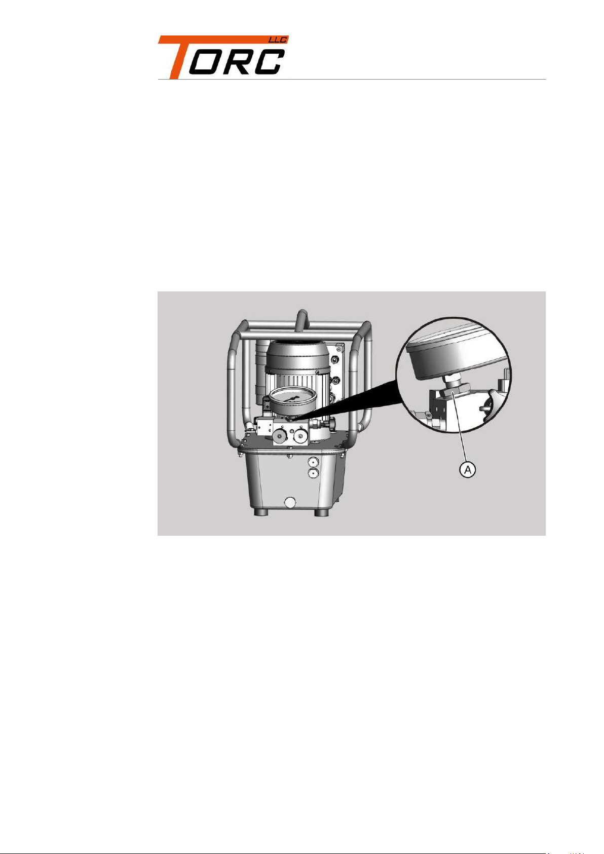
Replacing the pressure gage
To replace the pressure gage, proceed as follows:
Switch off the unit.
To depressurize the unit, press the stop button on the remote control
several times.
Disconnect the mains plug.
Release the screw connection (A) below the pressure gage.
Lift the pressure gage upwards to remove it.
Ensure that an intact O-ring is installed on the underside of the part to be
screwed in.
Place a new pressure gage of the same type on the screw fitting.
Fix the pressure gage with the screw fitting.

Malfunctions
20
Malfunctions
Malfunction
Possible cause
Corrective action
The pump is not
working.
Electrical components
are damaged.
Check the electrical
components, see page 25.
Replace damaged
electrical components or
have these replaced by the
manufacturer.
The power supply is
interrupted.
Check the power supply,
see page 27.
The remote control is
defective.
Check the remote control,
see page 31.
The motor only hums.
The stator is defective.
Check the motor windings,
see page 36.
Have the defective motor
windings repaired by the
manufacturer.
The capacitor is
defective.
Check the current of the
capacitor, see from
page 36.
Replace a defective
capacitor, see page 42.
No pressure or
pressure below 70 bar.
The solenoid valve is
defective.
Check the solenoid valve
electrically, see page 43.
Check the solenoid valve
hydraulically, see page 58.
Replace the defective
solenoid valve, see
page 47.
The torque valve is
defective.
Check the torque valve
hydraulically, see page 55
Replace the defective
torque valve, see page 86.
Leak on the pump
flange.
Check the pump flange,
see page 61.
Have the defective pump
flange repaired by the
manufacturer.
The screen filter is
blocked.
Check the screen filter, see
page 64.
Clean the blocked screen
filter, see page 64.
The maximum pressure
valve is leaking.
Check the maximum
pressure valve, see
page 65.
Replace the defective
maximum pressure valve,
see page 67.
Table of contents


