Ecotechnics SUN ECK TWIN 12 User manual

ECK TWIN 12 |SUN DUAL GAS 12
”Two-in-one” — the complete stations for R134a and HFO1234yf
User manual

INSTRUCTIONS MANUAL
-3-
INDEX
INDEX ................................................................................................................................. 3
INTRODUCTION ................................................................................................................. 6
CARE OF THE MANUAL .........................................................................................................6
CONDITIONS OF WARRANTY........................................................................................... 7
UNPACKING AND HANDLING INSTRUCTIONS.....................................................................7
GENERAL INFORMATION .................................................................................................8
END-OF-LIFE......................................................................................................................9
BATTERY DISPOSAL..............................................................................................................9
SAFETY RULES................................................................................................................ 10
REFRIGERANT AND LUBRICANT - PERSONAL PROTECTIVE EQUIPMENT AND
PRECAUTIONS .....................................................................................................................11
HOSES CONNECTION .........................................................................................................11
PRECAUTIONS FOR HANDLING AND USE OF R134a FLUIDS ..........................................12
RULES FOR WORKING WITH R1234yf FLUIDS...................................................................12
PRINCIPLES OF OPERATION 14
SETUP............................................................................................................................... 15
R134a refrigerant scale:.........................................................................................................15
R1234y refrigerant scale: .......................................................................................................15
THE MACHINE.................................................................................................................. 17
BODY SHELL COMPONENTS ..............................................................................................17
BASIC COMPONENTS..........................................................................................................18
CONTROL PANEL FUNCTION KEYS ...................................................................................20
ALARMS ................................................................................................................................24
ERROR CODES ....................................................................................................................25
Analyzer error codes* 25
Vacuum error codes 25
PRELIMINARY OPERATIONS...............................................................................................26
AUTOMATIC PROCEDURE.............................................................................................. 29
Edit VACUUM data ................................................................................................................30
Edit OIL data..........................................................................................................................30
Edit UV data...........................................................................................................................30
Edit GAS CHARGE data ........................................................................................................30
Edit GAS CHARGE mode ......................................................................................................32
START AUTOMATIC PROCEDURE......................................................................................32
MANUAL PROCEDURE.................................................................................................... 36
RECOVERY AND RECYCLING.............................................................................................36
VACUUM ...............................................................................................................................39

INSTRUCTIONS MANUAL
-4-
OIL+UV INJECTION .............................................................................................................42
EDIT OIL DATA 42
EDIT UV DATA 42
EDIT GAS CHARGE DATA 42
EDIT GAS CHARGE MODE 44
START PROCEDURE 44
CHARGE................................................................................................................................47
EDIT GAS CHARGE MODE 47
START PROCEDURE 48
SETUP...............................................................................................................................50
VACUUM SETTING ...............................................................................................................51
OPTIONS...............................................................................................................................51
OIL SETTING.........................................................................................................................52
DATABASE SETTING............................................................................................................52
SETUP HEADER PRINT........................................................................................................53
SET DATE / TIME..................................................................................................................54
LANGUAGE...........................................................................................................................54
MEASURE UNITS..................................................................................................................55
QUICKSETUP........................................................................................................................56
WI-FI ......................................................................................................................................57
PAIRING 57
AC-SERVICE24 58
ADD MACHINE 59
SERVICE ARCHIVE 59
REAL TIME 59
STATE MACHINE 59
ACCOUNT 59
LANGUAGE 60
PC / SMARTPHONE / TABLET 60
SMARTPHONE APP DOWNLOAD 60
MAINTENANCE.................................................................................................................61
TANK FILLING.......................................................................................................................62
AIR PURGE MANUAL............................................................................................................63
GAS ANALYSIS.....................................................................................................................64
GAS ANALYZER VERIFICATION 65
EMPTY HOSES .....................................................................................................................66
TEST N2 / N2+H2 ..................................................................................................................67
NITROGEN TEST (N2) 67
MIXTURE TEST (N2+H2) 69
CHANGE DRYER FILTER .....................................................................................................72
A/C PRESSURES CHECK.....................................................................................................76
STATIC DIAGNOSIS .............................................................................................................79
MAINTENANCE REPORT .....................................................................................................80
SERVICES ARCHIVE ............................................................................................................81
DATABASE ACTIVATION......................................................................................................84

INSTRUCTIONS MANUAL
-5-
DATABASE............................................................................................................................85
COUNTERS...........................................................................................................................86
CALIBRATION.......................................................................................................................87
R134a TANK CELL 88
R1234yf TANK CELL 89
R134a OIL 1 CELL 90
R134a OIL 2 (UV) CELL(if installed, depending on machine model) 90
R1234yf OIL 1 CELL 90
R1234yf OIL 2 (UV) CELL(if installed, depending on machine model) 90
USED OIL CELL 91
R134A A/C PRESSURE 92
R1234YF A/C PRESSURE 93
R134A TANK PRESSURE 94
R1234YF TANK PRESSURE 95
TEMPERATURE 96
RESTORE CALIBRATION 96
CHANGE OIL CONTAINER ...................................................................................................97
VACUUM PUMP OIL CHANGE .............................................................................................99
M.1) OIL TOP-UP 99
M.2) OIL CHANGE 101
CHOOSE TYPE OF GAS.....................................................................................................103
FILLING THE OIL 1 CONTAINER (R134a/R1234yf)............................................................105
FILLING THE OIL 2 (UV) CONTAINER (R134a/R1234yf)....................................................106
REPLACE THE OIL 1 CARTRIDGE (R134a/R1234yf).........................................................107
REPLACE THE OIL 2 (UV) CARTRIDGE (R134a/R1234yf).................................................108
EMPTYING THE USED OIL CONTAINER...........................................................................109
REPLACING THE PRINTER PAPER...................................................................................110
INFO.......................................................................................................................... 111

INSTRUCTIONS MANUAL
-6-
INTRODUCTION
This machine is a pressure unit as can be seen in the CE declaration of conformity and Data
plate. The equipment supplied conforms to the Essential Safety Requirements according to
Annex I of Directive 2014/68/UE (PED). Any work involving repairs, modifications, and/or
changing pressurized components or parts make safe use of the equipment very risky. Any
tasks done must be authorized by the Manufacturer.
This manual contains important information pertinent to operator safety.
Read this manual through before beginning operation of the machine.
The manufacturer reserves the right to modify this manual and the machine
itself with no prior notice. We therefore recommend checking any updates. This manual must
accompany the machine in case of sale or other transfer.
Any repair, modification, or changing of components not formally agreed with and authorized
by the manufacturer poses a risk of the conformity to Directive 2014/68/UE being nullified and
makes this pressure equipment a significant risk. If not authorized in writing the Manufacturer
considers the tasks indicated above to be tampering with the machine, which nullifies the initial
declaration of conformity issued, and so they do not accept any direct responsibility.
Braze welding of parts that contribute to the pressure strength of the equipment and the parts
directed attached to it was done by adequately qualified personnel, using adequate operating
methods. Approval of the operating methods and personnel was entrusted to a competent
outside party for category III pressure equipment, and any work on this equipment that involves
the need to carry out braze welding must comply with the requirements laid down in annex 1 of
Directive 2014/68/UE, or the Manufacturer must be contacted for the relevant information.
The pressure equipment has been inspected and tested, complete with the safety
accessories identified by the manufacturer as being of a direct discharge type with
calibrated air pressure. Testing and inspection of the accessories is not necessary prior
to starting up.
The pressure equipment must be subjected to routine inspections and checks when
operating, according to the relevant regulations and legal norms.
For the unit in question, it is hereby declared that a competent Authorized Body carried out
their part of the final check according to annex I of point 3.2.3 of Directive 2014/68/UE as well
as checking safety accessories and control devices in conformity to comma d) of art 5 of
Ministerial Decree 329 of 01/12/2004.
List of the critical components in terms of PED safety DIR 2014/68/UE
Condenser, dehydrator filters, distributor, refrigerant storage bottle, airtight compressor, safety
pressure switch, pressure transducers, and safety valves.
The operator has to check/substitute the PED critical components before their respective end
of life (according to national law)
CARE OF THE MANUAL
This manual must be kept for the entire life of the machine and protected against humidity and
excessive heat. Take care not to damage this manual in any way during consultation.

INSTRUCTIONS MANUAL
-7-
CONDITIONS OF WARRANTY
Refer to CONDITIONS OF WARRANTY booklet supplied with the machine.
UNPACKING AND HANDLING INSTRUCTIONS
NOTE: keep the original packaging and re-use it for subsequent transportation
NOTE: use the handle (ref.20, Fig.8) to move the machine.
INSTRUCTIONS MANUAL
-8-
GENERAL INFORMATION
Machine identification information is printed on the data plate on the rear of the machine (see
Fig.1). Overall machine dimensions:
Height: 1070 mm Width: 620 mm
Depth: 670 mm Weight: 110 kg
Operating temperature 10/50°C Storage temperature -25/+50°C
Like any equipment with moving parts, the machine inevitably produces noise. The
construction system, paneling, and special provisions adopted by the Manufacturer are such
that during work the average noise level of the machine is not in excess of 70 dB (A).
Model Voltage (V) Power (W) Frequency (Hz) Fuse (A)
100 Volt Machine 100 1100 50/60 16
110 Volt Machine 110 1100 50/60 16
230 Volt machine 230 1100 50/60 8
CAUTION: avoid the use of external extensions and verify that all electrical systems and
devices connected comply with the regulations in force and in good state of preservation
FIG. 1
DATA PLATE
INSTRUCTIONS MANUAL
-9-
END-OF-LIFE
The symbol on the right indicates that in accordance with Directive 2012/19/UE the
machine may not be disposed of as ordinary municipal waste but must be
delivered to a specialized center for separation and disposal of WEEE (Waste
Electrical and Electronic Equipment) or be returned to the dealer in case of
purchase of a new machine. Current legislation provides severe sanctions in the case of
disposal of WEEE into the environment. If improperly used or disposed of into the environment,
electrical and electronic equipment can release substances dangerous for the environment and
for human health.
BATTERY DISPOSAL
The machine uses an electronics card containing a Lithium battery (ref:1, Fig.2). When
discharged, it must be removed by expert personnel trained in machine demolition.
FIG. 2
1
B
A
C

INSTRUCTIONS MANUAL
-10-
SAFETY RULES
This machine is a piece of equipment designed to recover R1234yf and R134a from air
conditioning systems (A/C) for vehicles. The machine must be used by qualified personnel and
can only be used correctly after having read this manual that also contains the basic safety
rules listed below:
-Wear gloves and safety glasses.
-Do not expose to direct sunlight and rain.
-Before doing any task check the vehicle’s operating and maintenance handbook to
determine the type of refrigeration fluid used in the A/C system.
-No smoking in the vicinity of the machine and while working.
-The environmental conditions of use of the equipment are as follows:
-• temperature from + 10 ° C to + 50 ° C;
-• pressure from 80 kPa (0.8 bar) to 110 kPa (1.1 bar);
-• air with normal oxygen content, generally 21% v/v.
-Machine storage: when not in use, the machine must be deposited in a dedicated
place with the following characteristics:
-1. Forced ventilation with at least one air change of the entire volume of the
environment every 24 hours.
-2. There must not be any sources of ignition, such as sources of heat, open flames,
sparks of mechanical origin (eg: due to grinding), electrical material (in particular,
the area where the machine is to be stored must not have power outlets electrical
installation less than 900 mm from the floor), stray electric currents and cathodic
corrosion (check that the electrical distribution system complies with the mandatory
legislative provisions); static electricity (check the earthing of the plant's electrical
distribution system), lightning.
-3. Storage temperature -25/50 ° C
-Use the machine away from heat sources, naked flames and/or sparks.
-Always make sure that when you switch off the engine the vehicle’s ignition key is turned to
the Fully Off position.
-Always connect the machine’s piping using the RED rapid coupling to the high pressure
branch of the A/C system.
-Always connect the machine’s piping using the BLUE rapid coupling to the low pressure
branch of the A/C system.
-Keep the connection pipes away from moving or rotating items or elements (cooling fan,
alternator, etc.).
-Keep the connection pipes away from hot items or elements (engine exhaust pipes, radiator,
etc.).
-Always fill the A/C system with the quantity of fluid recommended by the manufacturer.
Never exceed this quantity.
-Always check the oil levels prior to each operation.
-Always keep the oil at the correct quantity.
-Before connecting the machine to the electrical system, check that the power supply voltage
and frequency are the same as the values indicated on the CE plate.
The bottle must be filled to 80% of its maximum capacity to leave a plenum chamber for
the gas to absorb any increases in pressure.
-Never touch the taps on the inner bottle.
-Throw the oil taken out of the A/C system and the vacuum pump into the relevant containers
for spent oils.

INSTRUCTIONS MANUAL
-11-
-Change the filters at the intervals laid down, using only filters recommended by the
manufacturer.
-Only use the oils recommended by the manufacturer.
-Never confuse the vacuum pump oil with the oil for the air-conditioning systems.
Failure to comply with any of these safety rules leads to any form of guarantee for the machine
being rendered null and void.
Machine is provided with class III safety valve, in case of malfunctioning it can create an
external sack of flammable gas; keep the machine in well ventilated area.
WARNING: R134a and/or R1234yf vapor/gas refrigerant are heavier than air and may thicken
on the floor or inside the cavity/pits and cause choking by reducing oxygen available for
breathing.
At high temperatures the refrigerant decomposes releasing toxic and caustic substances,
hazardous for the operator and the environment. Avoid inhalation of the refrigerants and A/C
system oils .
Exposure can irritate the eyes and airways.
WARNING! The machine must be connected to a socket with effective ground
WARNING: This is a class “A” product. In a domestic environment this product may
cause radio interference. In such cases, the user may be required to take adequate
measures.
REFRIGERANT AND LUBRICANT - PERSONAL
PROTECTIVE EQUIPMENT AND PRECAUTIONS
Handled with caution refrigerants and pressure vessels, since otherwise there could be health
risks .
The operator must wear safety glasses, gloves and suitable clothing to work , contact with
refrigerant may cause blindness (eyes), and other physical damage (frostbite) to the operator.
Avoid contact with the skin, the low boiling temperature (about -26°C for R134a and about -
30°C for R1234yf ) can cause cold burns.
Do not change the setting of the relevant devices for safety, do not remove the seals of the
safety valves and control systems . Do not use external tanks or other storage containers that
are not approved, or without safety valves.
During the functioning, the air vents and
ventilation equipment must not be blocked or
covered
HOSES CONNECTION
Hoses may contain refrigerant under pressure. Before substitute the quick coupler verify the
corresponding pressure in the service hoses (gauge).
The machine is equipped with the following safety devices:
SAFETY PRESSURE: stops the compressor in case of excessive
pressure
SAFETY VALVE: opens when the pressure inside the system reaches a
level of pressure above the estimated limits.
MAIN SWITCH: allows the machine’s turnoff by sectioning of the power
line. Prescribing however disconnection from the mains plug of the power
cord before servicing
IT IS NOT ALLOWED ANY KIND OF TAMPERING OF THE SAFETY
DEVICES MENTIONED ABOVE

INSTRUCTIONS MANUAL
-12-
PRECAUTIONS FOR HANDLING AND USE OF R134a
FLUIDS
Refrigerant fluids expand to the gaseous state in standard environmental conditions. In order
that they may be shipped and used they must be compressed into suitable bottles. We
therefore recommend observing all the general precautions applicable to handling of
pressurized containers. In the case of R134a in particular, we suggest the following special
precautions. Avoid inhaling highly concentrated vapors even for short periods of time, since
such vapors can cause loss of consciousness or death. R134a is not flammable, but if the
vapor is exposed to open flames or incandescent surfaces it may undergo thermal
decomposition and form acid substances. The acrid and pungent odor of these products of
decomposition is sufficient to signal their presence. We therefore recommend avoiding use of
R134a near open flames and incandescent elements. There exists no evidence of risks
deriving from transdermal absorption of R134a Nevertheless, due to the low boiling point of the
liquid, it is advisable to wear protective garments such as to ensure that no jets of liquid or gas
can come into contact with the skin. The use of goggles to avoid contact with the eyes is
especially recommended, since the refrigerant liquid or gas can cause freezing of the ocular
fluids. Moreover, we strongly advise users to avoid dispersing the R134a refrigerant fluid
utilized in the machine since it is a substance that contributes to raising the temperature of the
planet, with a global warming potential(GWP) of 1300.
RULES FOR WORKING WITH R1234yf FLUIDS
Under ambient conditions refrigerant fluids are gases. In order to be able to transport and use
them they must be compressed in specific bottles. The precautions for pressure vessels must
therefore be applied.
In particular, for R1234yf be careful of the following situations:
-Inhalation of vapours at very high concentrations, even for short periods of time, must be
avoided as it can cause unconsciousness and sudden death.
-R1234yf is flammable and if the vapour is exposed to naked flames or red hot surfaces it
can undergo thermal decomposition with the formation of acid products. The acrid, pungent
odour of these products of decomposition is sufficient to warn of their presence. Avoid
finding yourself in the conditions just mentioned.
-There is no proof of risks resulting from the absorption of R1234yf through the skin,
however, due to its low boiling point it is advisable to wear protective clothing that can
prevent any liquid sprayed or vapour reaching the skin and especially the eyes, where they
could cause the eye fluids to congeal.
-We also recommend no dispersing the R1234yf refrigerant fluid used in the machine,
because it is a substance that contributes to heating the planet, with a global warming
potential (GWP) of 4.
ANY USE THAT DIFFERS FROM THAT JUST DESCRIBED IS NOT ALLOWED BY THE
MANUFACTURER.
Uses not allowed
This machine may not be used for tasks not envisaged or to handle products other than
those envisaged, or for uses other than those specified in paragraphs "Conditions of use
envisaged".
The following are forbidden:
1. Using the machine with a constructive configuration that differs from that envisaged by
the manufacturer.
2. Using the machine in places at risk of explosion and/or fire
INSTRUCTIONS MANUAL
-13-
3. Adding other systems and/or equipment not considered by the manufacturer in their
working design.
4. Using the machine without the perimeter protection and/or the fixed and mobile guards
tampered wit or removed.
5. Connecting the machine to energy sources other than those envisaged by the
manufacturer.
6. Using the commercial devices for a purpose other than that envisaged by the
manufacturer.
Actions not allowed on the part of the operator
The operator tasked with operating, supervising, and maintaining the machine must not:
1. Use the machine if they have not been trained and informed beforehand as called for
by the law on safety in the workplace
2. Fail to act as described in the operating instructions.
3. Allow unauthorized people to approach and/or use the machine.
4. Tamper with the moving and fixed guards that provide perimeter protection, thereby
also exposing other operators and people to risks of a residual nature.
5. Remove or alter the safety signs (such as pictograms, warning signs, and others) on
the machine.
6. Use the machine without having first read and understood the behavioral, operating
and maintenance information contained in the operating instructions.
7. Leave the maneuvering keys on the electromechanical controls (selectors), pneumatic
controls, and doors of the housings for electrical and electronic materials (electrical
panels and derivation boxes).
8. Carry out the following operations as they pose residual risks:
Adjust the mechanical, pneumatic, or electrical parts on the machine while it is
working.
Remove the mechanical, pneumatic, or electrical parts on the machine while it is
working.
Remove the protective devices for mechanical, pneumatic, or electrical parts on the
machine while it is working.
Allow the machine to run when the electrical panels are open.
These uses, that cannot be avoided by way of construction, must not be allowed.
9. If service station fall down, or is hit, or in case of big leakage, or sounds of flowing gas:
an internal damage could happen, also if externally the machine seems good, and it
is still working;
the machine must be taken outdoor or in a very ventilated place.
No fire, no smoke, no workers, no cars nearby this service station.
The service station must be fully tested by a trained technician before to be used
again.
WARNING
The employer (or safety manager) is obliged to see to it that the machine is not
used in an improper manner, putting the health of the operator and people
exposed first.
The operator is obliged to inform their employer (or the system safety manager)
if there is a danger of improper use of the machine since, as an instructed
person, the operator is responsible for the use that is to be made of the
machine.

INSTRUCTIONS MANUAL
-14-
PRINCIPLES OF OPERATION
In a single series of operations, the machine permits recovering and recycling refrigerant fluids
(R134a or R1234yf) with no risk of releasing the fluids into the environment, and also permits
purging the A/C system of humidity and deposits contained in the oil.
The machine is in fact equipped with a built-in evaporator/separator that removes oil and other
impurities from the refrigerant fluid recovered from the A/C system and collects them in a
container for that purpose.
The fluid is then filtered and returned perfectly recycled to the bottle installed on the machine.
The machine also permits running certain operational and seal tests on the A/C system.

INSTRUCTIONS MANUAL
-15-
SETUP
The machine is supplied fully assembled and tested.
Referring to Figure 3 remove the protections under the refrigerant scales as follows:
R134a refrigerant scale:
- In order to remove the protections under the refrigerant scale the locking knob (ref.1b,
Fig.3) has to be unscrewed
- Connect the machine to the electrical supply and switch it on
- Check if the value of refrigerant scale is correct.
NOTE: in the event that the equipment has to be transported, the refrigerant bottle scale
should be locked in place as follows:
- Switch the machine on.
- Screwed the knob (ref.1b, Fig.3) until the display signals ZERO availability.
R1234y refrigerant scale:
- In order to remove the protections under the refrigerant scale the locking knob (ref.1a,
Fig.3) has to be unscrewed
- Connect the machine to the electrical supply and switch it on
- Check if the value of refrigerant scale is correct.
NOTE: in the event that the equipment has to be transported, the refrigerant bottle scale
should be locked in place as follows:
- Switch the machine on.
- Screwed the knob (ref.1a, Fig.3) until the display signals ZERO availability.

INSTRUCTIONS MANUAL
-16-
1a
FIG. 3
1b
INSTRUCTIONS MANUAL
-17-
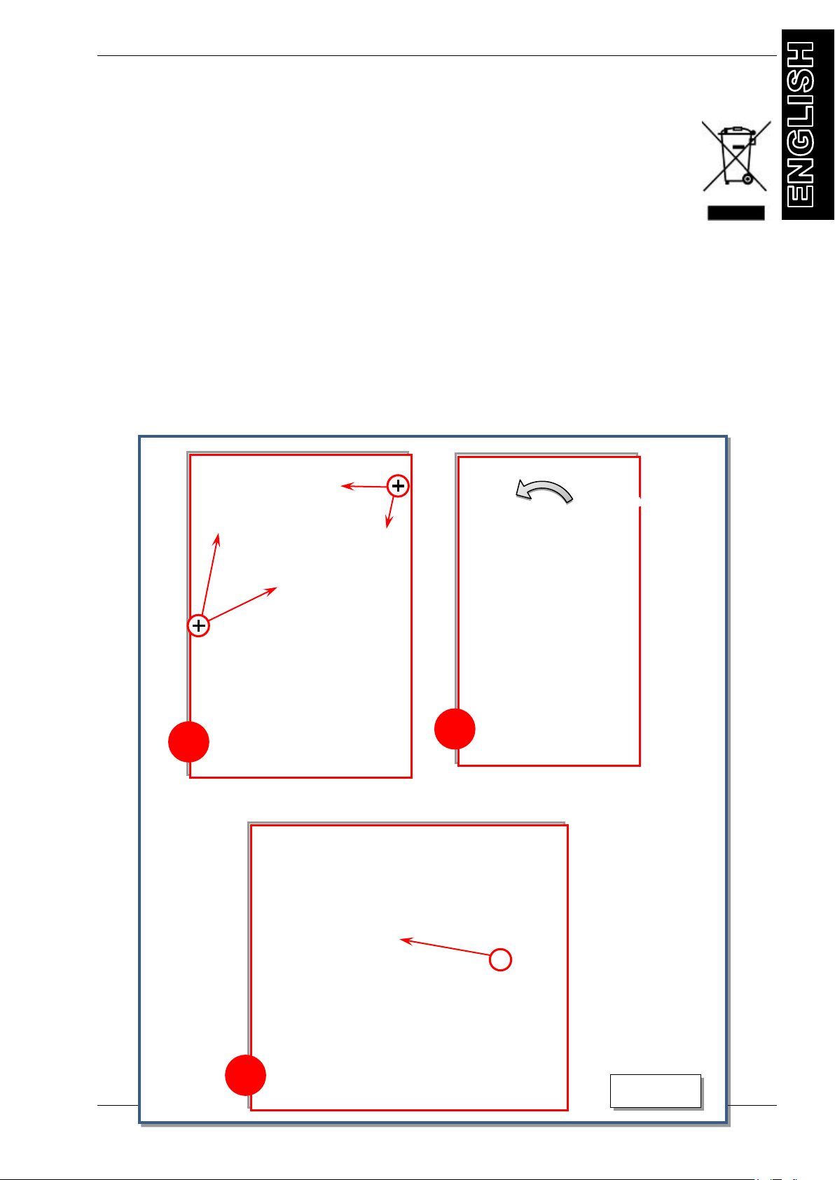
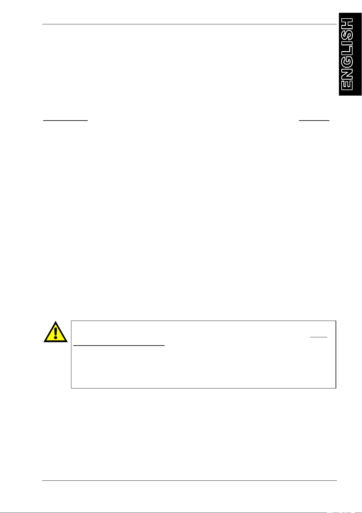
FIG. 4
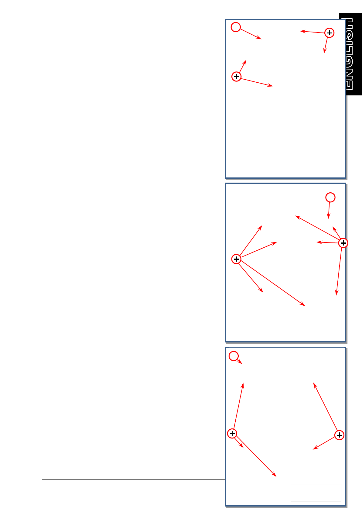
FIG. 5
FIG. 6
1
2
3
THE MACHINE
BODY SHELL COMPONENTS
1. Upper plastic carter , refer to Fig.4
Disassembly: Screw off 4 screws marked (+)
2. Front plastic carter , refer to Fig.5
Disassembly: Screw off 8 screws marked (+)
3. Rear plastic carter , refer to Fig.6
Disassembly: Screw off 5 screws marked (+)

INSTRUCTIONS MANUAL
-18-
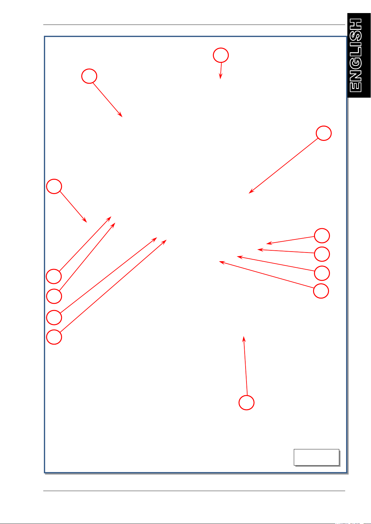
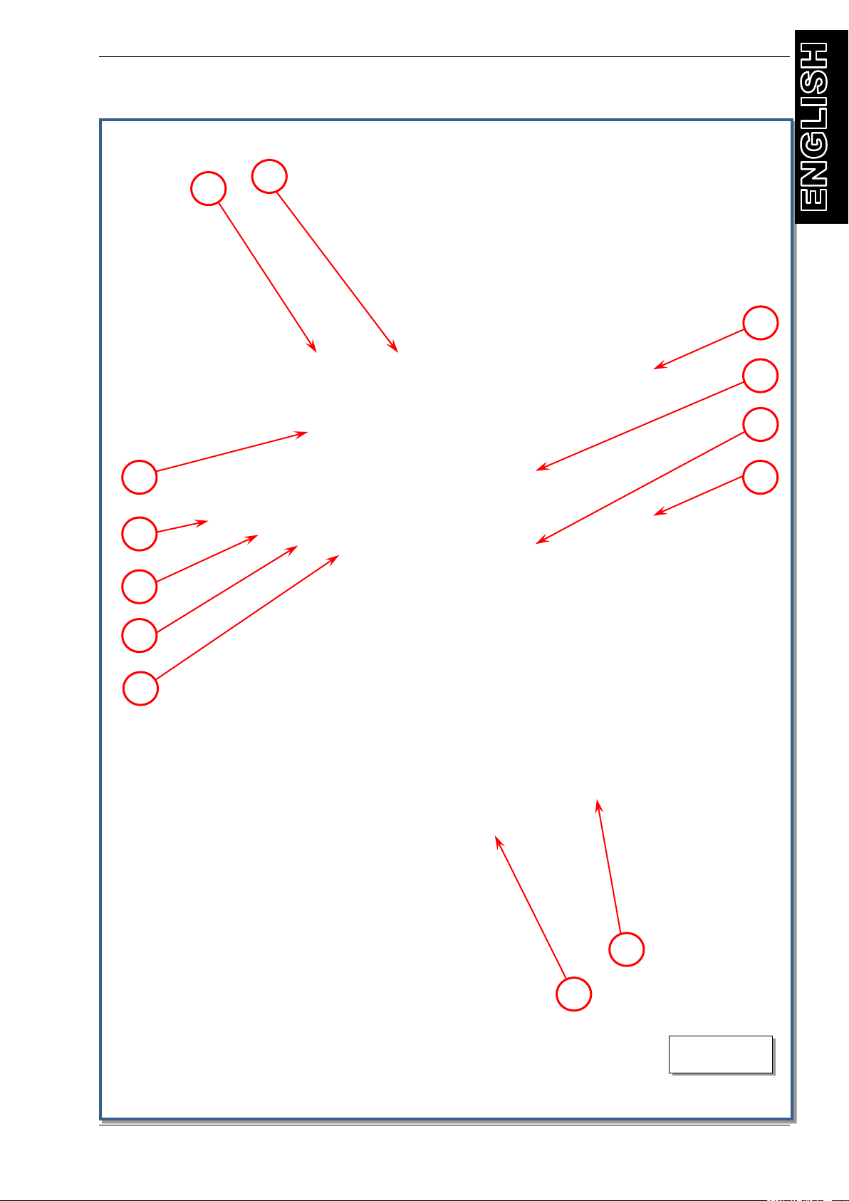
BASIC COMPONENTS
refer to Fig.7, 8, 9 and 10
1. control panel
2. tool tray
3. external R1234yf gas analyzer *
4. R1234yf UV container **
5. R1234yf new oil container **
6. R134a new oil container **
7. R134a UV container **
8. used oil container
9. R1234yf high pressure threaded connector
10.R1234yf low pressure threaded connector
11.R134a low pressure threaded connector
12.R134a high pressure threaded connector
13.front pocket stowing hoses
14.R134a high pressure manometer
15.R134a low pressure manometer
16.printer
17.R1234yf low pressure manometer
18.R1234yf high pressure manometer
19.touch screen display
20.handle
21.R1234yf high pressure quick fitting
22.R1234yf low pressure quick fitting
23.R134a low pressure quick fitting
24.R134a high pressure quick fitting
25.R1234yf compressor
26.R1234yf dryer filter
27.R134a dryer filter
28.Fuse (8A 230v;16A 100-110v)
29.socket for electrical supply plug
30.main switch
31.ventilation grid
32.USB connection
33.rear wheel
34.R134a refrigerant bottle
35.R1234yf refrigerant bottle
36.R1234yf bottle heater
37.R134a bottle heater
38.R134a compressor
39.vacuum pump
40.R1234yf UV collapsible cartridge **
41.R1234yf new oil collapsible cartridge **
42.R134a new oil collapsible cartridge **
43.R134a UV collapsible cartridge **
44.Quick coupler gas analyzer fitting *
45.rear pocket
46.nitrogen quick fitting
47.fan
48.front swirling wheel
* optional
** if installed, depending on machine model
INSTRUCTIONS MANUAL
-19-
FIG.7
1
2
13
12
11
10
9
3
4
5
6
7
8

INSTRUCTIONS MANUAL
-20-
FIG.8
30
14
15
16
17
18
19
20
21
22
23
24
25
26
27
28
29
INSTRUCTIONS MANUAL
-21-
FIG.9
40
39
38
37
36
35
34
32
31
44
43
42
41
This manual suits for next models
1
Table of contents
Other Ecotechnics Service Equipment manuals


