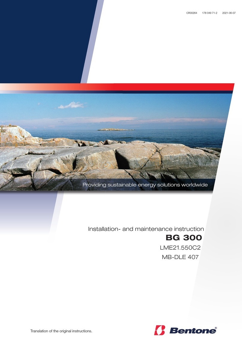
Bentone BG550 Series Technical specifications


Other manuals for BG550 Series
2
This manual suits for next models
2
Table of contents
Other Bentone Burner manuals
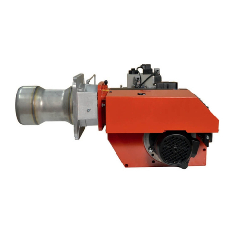
Bentone
Bentone BG 450-2 Technical specifications
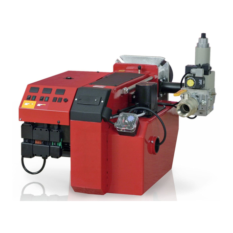
Bentone
Bentone BG550 Series Technical specifications
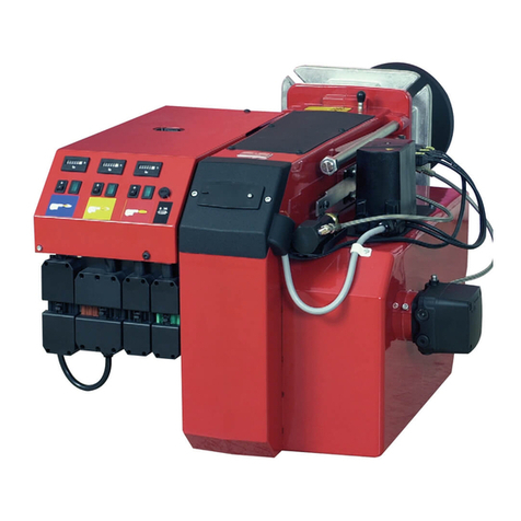
Bentone
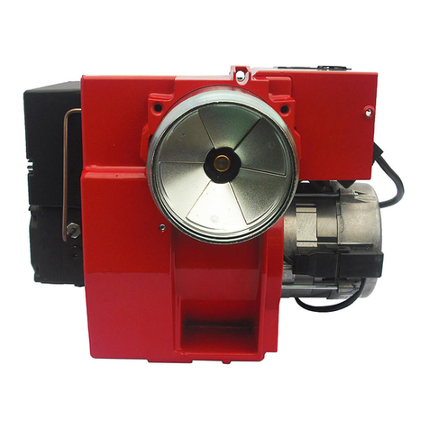
Bentone B 55-3R Technical specifications
Bentone
Bentone BG 450 LN Technical specifications

Bentone
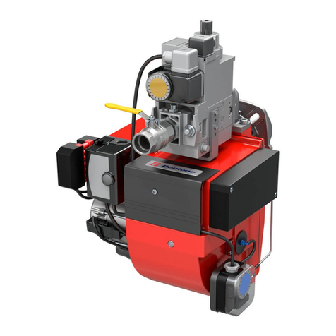
Bentone B55 Technical specifications
Bentone
Bentone BG550-2 Technical specifications

Bentone
Bentone B 30 A2.2H Technical specifications

Bentone
Bentone B 45 A Technical specifications
Bentone
Bentone STERLING 40 ST108PL Technical specifications

Bentone
Bentone B 45 A2.2 RME Technical specifications
Bentone
Bentone STG 146/2 Technical specifications

Bentone
Bentone B 2 Series Technical specifications
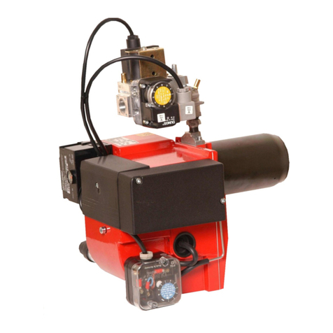
Bentone
Bentone STG 120/2 Technical specifications

Bentone
Bentone STG 146i/2 Technical specifications
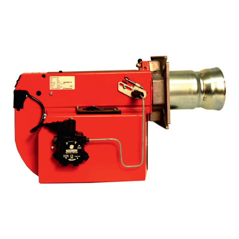
Bentone
Bentone B 40 A Technical specifications

Bentone
Bentone BG 550-2 LME22 Technical specifications

Bentone
Bentone B 45i A2.2H J/K Technical specifications
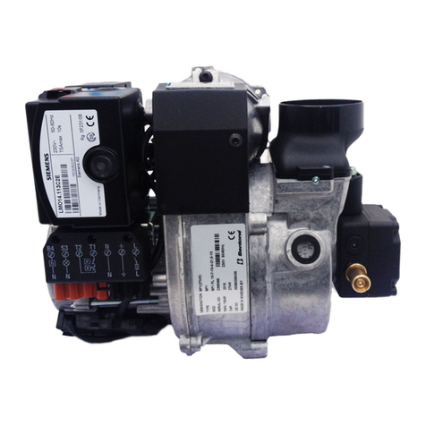
Bentone
Bentone BF1 Series Technical specifications

Bentone
Bentone BENTOFLEX ST 120 KA Technical specifications
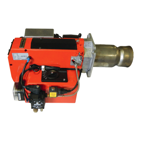
Bentone
Bentone B 30 A2.2 Technical specifications
Popular Burner manuals by other brands
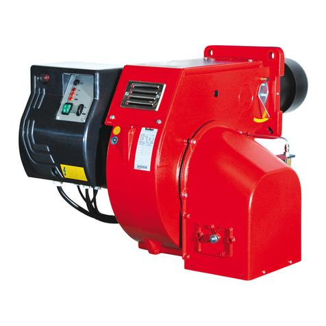
Ecoflam
Ecoflam MAIOR P 60 AB manual

Narita
Narita NHP-802 instruction manual

Town & Country Fireplaces
Town & Country Fireplaces TC36.NG04C instructions

Riello
Riello RL 70 Installation, use and maintenance instructions

Riello
Riello 370T1 Series Installation, use and maintenance instructions
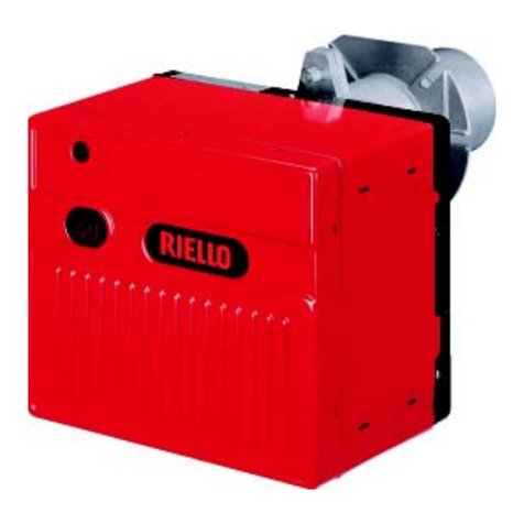
Riello
Riello 40 FS8 Installation, use and maintenance instructions

Riello
Riello RDB1 12/18 WH Installation, use and maintenance instructions

Riello
Riello 809 T80 Installation, use and maintenance instructions
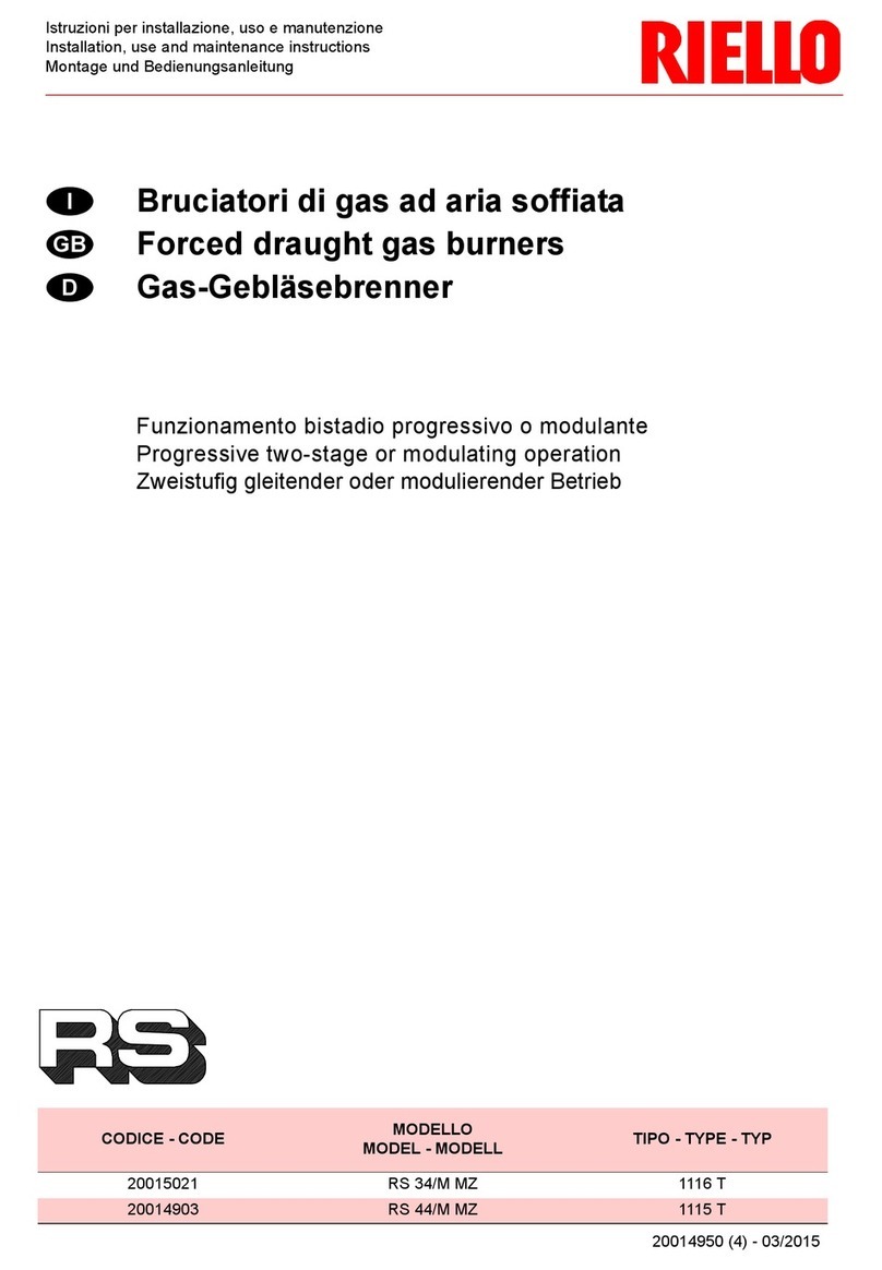
Riello
Riello RS 44/M MZ Installation, use and maintenance instructions
Viking
Viking F20921B Use & installation guide
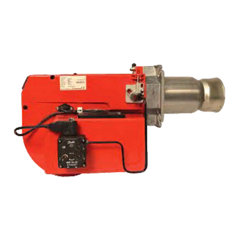
Enertech
Enertech Bentone B 30 2A Installation and maintenance instruction

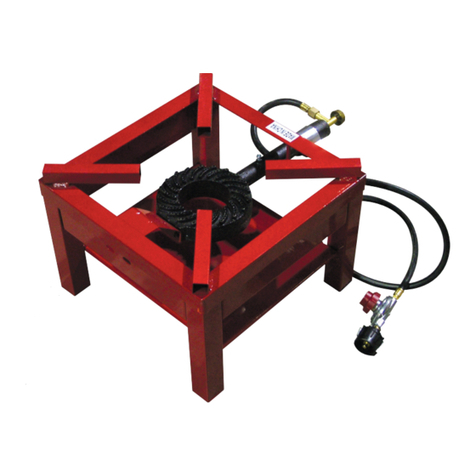
Carolina Cooker
Carolina Cooker M56913 owner's guide
Omcan
Omcan CE-CN-006 instruction manual
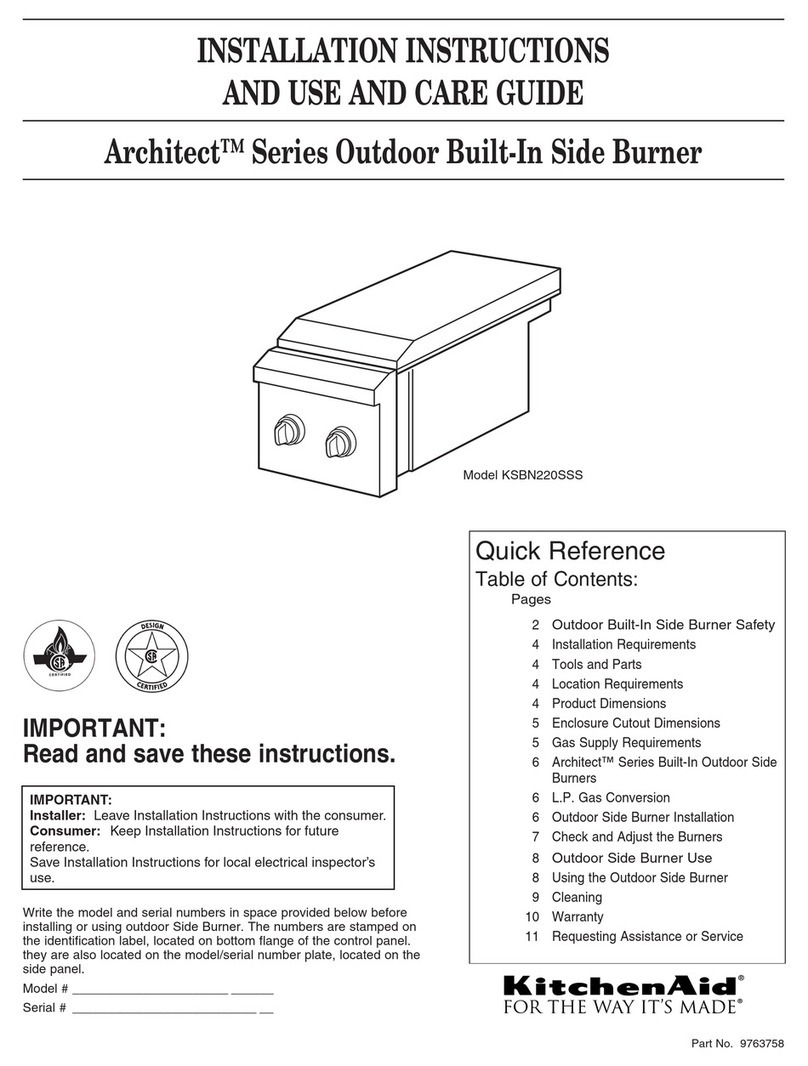
KitchenAid
KitchenAid KSBN220SSS Installation instructions and use and care guide
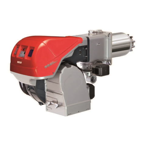
Riello
Riello RS 55/E BLU Installation, use and maintenance instructions
Jetmaster
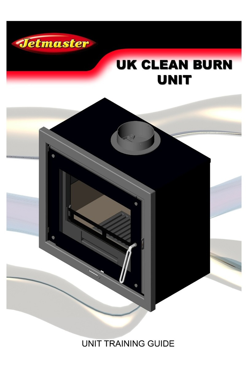
Jetmaster INSET STOVE MKIII 60i user guide

Heta
Heta SCAN-LINE GREEN 250 Operating and installation instructions

Eclipse
Eclipse ThermJet TJSR0020 installation guide
