Benzlers BD Series Maintenance and service guide

IMC-1.00GB01/11
Series BD - Screw Jacks
Installation & Maintenance

Product Safety Information
General - The following information is important in ensuring safety. It must be brought to the attention of personnel involved in the selection
of power transmission equipment, those responsible for the design of the machinery in which it is to be incorporated and those involved in its
installation, use and maintenance.
Our equipment will operate safely provided it is selected, installed, used and maintained properly. As with any power transmission equipment
proper precautions must be taken as indicated in the following paragraphs, to ensure safety.
Potential Hazards - these are not necessarily listed in any order of severity as the degree of danger varies in individual circumstances. It is
important therefore that the list is studied in its entirety:-
1) Fire/Explosion
(a) Oil mists and vapour are generated within gear units. It is therefore dangerous to use naked lights in the proximity of gearbox openings,
GXHWRWKHULVNRI¿UHRUH[SORVLRQ
E,QWKHHYHQWRI¿UHRUVHULRXVRYHUKHDWLQJRYHUR&FHUWDLQPDWHULDOVUXEEHUSODVWLFVHWFPD\GHFRPSRVHDQGSURGXFHIXPHV
&DUHVKRXOGEHWDNHQWRDYRLGH[SRVXUHWRWKHIXPHVDQGWKHUHPDLQVRIEXUQHGRURYHUKHDWHGSODVWLFUXEEHUPDWHULDOVVKRXOGEH
handled with rubber gloves.
2) Guards - Rotating shafts and couplings must be guarded to eliminate the possibility of physical contact or entanglement of clothing. It should
EHRIULJLGFRQVWUXFWLRQDQG¿UPO\VHFXUHG
1RLVH+LJKVSHHGJHDUER[HVDQGJHDUER[GULYHQPDFKLQHU\PD\SURGXFHQRLVHOHYHOVZKLFKDUHGDPDJLQJWRWKHKHDULQJZLWKSURORQJHG
exposure. Ear defenders should be provided for personnel in these circumstances. Reference should be made to the Department of
(PSOR\PHQW&RGHRI3UDFWLFHIRUUHGXFLQJH[SRVXUHRIHPSOR\HGSHUVRQVWRQRLVH
4) Lifting - Where provided (on larger units) only the lifting points or eyebolts must be used for lifting operations (see maintenance manual or
general arrangement drawing for lifting point positions). Failure to use the lifting points provided may result in personal injury and/or damage
to the product or surrounding equipment. Keep clear of raised equipment.
5) Lubricants and Lubrication
D3URORQJHGFRQWDFWZLWKOXEULFDQWVFDQEHGHWULPHQWDOWRWKHVNLQ7KHPDQXIDFWXUHU¶VLQVWUXFWLRQPXVWEHIROORZHGZKHQKDQGOLQJ
lubricants.
(b) The lubrication status of the equipment must be checked before commissioning. Read and carry out all instructions on the lubricant
SODWHDQGLQWKHLQVWDOODWLRQDQGPDLQWHQDQFHOLWHUDWXUH+HHGDOOZDUQLQJWDJV)DLOXUHWRGRVRFRXOGUHVXOWLQPHFKDQLFDOGDPDJHDQGLQ
extreme cases risk of injury to personnel.
6) Electrical Equipment - Observe hazard warnings on electrical equipment and isolate power before working on the gearbox or associated
equipment, in order to prevent the machinery being started.
7) Installation, Maintenance and Storage
(a) In the event that equipment is to be held in storage, for a period exceeding 6 months, prior to installation or commissioning, we must be
consulted regarding special preservation requirements. Unless otherwise agreed, equipment must be stored in a building protected from
extremes of temperature and humidity to prevent deterioration.
The rotating components (gears and shafts) must be turned a few revolutions once a month (to prevent bearings brinelling).
E([WHUQDOJHDUER[FRPSRQHQWVPD\EHVXSSOLHGZLWKSUHVHUYDWLYHPDWHULDOVDSSOLHGLQWKHIRUPRID³ZD[HG´WDSHRYHUZUDSRUZD[¿OP
preservative. Gloves should be worn when removing these materials. The former can be removed manually, the latter using white spirit as
a solvent.
3UHVHUYDWLYHVDSSOLHGWRWKHLQWHUQDOSDUWVRIWKHJHDUXQLWVGRQRWUHTXLUHUHPRYDOSULRUWRRSHUDWLRQ
F,QVWDOODWLRQPXVWEHSHUIRUPHGLQDFFRUGDQFHZLWKWKHPDQXIDFWXUHU¶VLQVWUXFWLRQVDQGEHXQGHUWDNHQE\VXLWDEO\TXDOL¿HGSHUVRQQHO
(d) Before working on a gearbox or associated equipment, ensure that the load has been removed from the system to eliminate the possibility
of any movement of the machinery and isolate power supply. Where necessary, provide mechanical means to ensure the machinery
cannot move or rotate. Ensure removal of such devices after work is complete.
(e) Ensure the proper maintenance of gearboxes in operation. Use only the correct tools and our approved spare parts for repair and
PDLQWHQDQFH&RQVXOWWKH0DLQWHQDQFH0DQXDOEHIRUHGLVPDQWOLQJRUSHUIRUPLQJPDLQWHQDQFHZRUN
+RW6XUIDFHVDQG/XEULFDQWV
D'XULQJRSHUDWLRQJHDUXQLWVPD\EHFRPHVXI¿FLHQWO\KRWWRFDXVHVNLQEXUQV&DUHPXVWEHWDNHQWRDYRLGDFFLGHQWDOFRQWDFW
E$IWHUH[WHQGHGUXQQLQJWKHOXEULFDQWLQJHDUXQLWVDQGOXEULFDWLRQV\VWHPVPD\UHDFKWHPSHUDWXUHVVXI¿FLHQWWRFDXVHEXUQV$OORZ
equipment to cool before servicing or performing adjustments.
9) Selection and Design
(a) Where gear units provide a backstop facility, ensure that back-up systems are provided if failure of the backstop device would endanger
personnel or result in damage.
(b) The driving and driven equipment must be correctly selected to ensure that the complete machinery installation will perform satisfactorily,
avoiding system critical speeds, system torsional vibration, etc.
(c) The equipment must not be operated in an environment or at speeds, powers, torques or with external loads beyond those for which it
was designed.
(d) As improvements in design are being made continually the contents of this catalogue are not to be regarded as binding in detail, and
drawings and capacities are subject to alterations without notice.
The above guidance is based on the current state of knowledge and our best assessment of the potential hazards in the operation of the gear units
.
$Q\IXUWKHULQIRUPDWLRQRUFODUL¿FDWLRQUHTXLUHGPD\EHREWDLQHGE\FRQWDFWLQJRXU$SSOLFDWLRQ(QJLQHHUV
IMPORTANT
PRODUCT SAFETY

1 IDENTIFICATION ...................................................................................1
1.1 Machine description .........................................................................................1
1.1.1 Description of purpose...........................................................................1
1.1.2 Reasonably foreseeable misuse and prohibited usages ......................1
1.1.3 System overview ....................................................................................2
1.1.4 Drawings/layouts ...................................................................................2
1.2 Manufacturer and technical data .....................................................................3
1.2.1 Identification...........................................................................................3
1.2.2 External Electrical Power — Supply data..............................................3
1.2.3 IP code, clear text...................................................................................4
1.2.4 Environmental conditions and limits.....................................................4
1.3 Product marking ...............................................................................................5
1.3.1 Product sign ...........................................................................................5
1.3.2 Option – extra sign according to ATEX directive....................................6
1.3.3 Understanding ATEX Directive - Markings............................................7
2 USE OF THIS MANUAL .......................................................................... 9
2.1 General information about this manual...........................................................9
2.2 Important information about this manual .......................................................9
2.3 Target group for this information .....................................................................9
2.3.1 Demands on personnel..........................................................................9
2.3.2 Procedure for revision and amendment................................................9
3 DESCRIPTION OF FUNCTION.............................................................. 10
3.1 Overall .............................................................................................................10
3.1.1 Control devices.....................................................................................11
3.2 Options ............................................................................................................12
3.2.1 Stop nut (SM)........................................................................................12
3.2.2 Stop nut (SM) + Limit Switch (LS)........................................................13
3.2.3 Locked against rotation – two options ................................................13
3.2.4 LR - Locked Against Rotation (Tube)...................................................14
3.2.5 LRK - Locked Against Rotation (Key) ..................................................15
3.2.6 Safety Nut (SHM)..................................................................................15
3.2.7 Antibacklash (ABL)...............................................................................16
4 SAFETY INFORMATION ....................................................................... 17
4.1 General machine safety................................................................................. 17
4.1.1 Emergency stop function .....................................................................17
4.1.2 Safety layout – emergency & safety stops zones................................17
4.1.3 Hazard text ...........................................................................................17
4.2 Operators locations.........................................................................................18
4.2.1 Noise.....................................................................................................18
4.2.2 Stability .................................................................................................18
4.2.3 Remaining risks ...................................................................................19
4.3 Personal protection, unintentional use..........................................................20
4.4 Safety instruction ............................................................................................20
4.4.1 Specific safety rules .............................................................................20
5 PREPARATIONS BEFORE USE ............................................................ 21
5.1 Safety precautions before use ........................................................................21
5.2 Transport and storage ....................................................................................21
5.2.1 Repackaging to prevent damage in transport.....................................21
5.2.2 Unpacking.............................................................................................21
5.2.3 Safely disposing of packaging material...............................................21
5.3 Preparatory work before installation and assembling..................................22
5.3.1 Prior to Installation ..............................................................................22
5.3.2 Fitting of components to the unit input shaft......................................22
5.3.3 Lifting....................................................................................................23
5.4 Installation ......................................................................................................24
5.4.1 Fitting the screw jack to the machine .................................................24
5.4.2 Units for use in a potentially explosive atmosphere...........................25
5.4.3 Motor Connections...............................................................................26

6 OPERATORS SETTINGS ETC ............................................................... 27
6.1 Instructions from sub suppliers – Quick reference.......................................27
7 OPERATING INSTRUCTIONS ............................................................... 27
7.1 Preparations before start ...............................................................................27
7.1.1 Start-up of safety systems...................................................................27
7.2 Operation.........................................................................................................28
7.2.1 Noise.....................................................................................................28
7.2.2 General safety ......................................................................................28
7.2.3 Initial start up in a potentially explosive atmosphere.........................28
7.2.4 Spillage of grease.................................................................................28
8 EMERGENCY, MISHAP AND SUSPENSION ......................................... 28
8.1 Change of direction of motion, relief of stored energy..................................28
8.2 Measures for the escape and rescue of trapped persons.............................28
8.3 Method to be followed in cases of accident or breakdown ...........................29
8.4 Storing and protecting ....................................................................................29
8.5 Taking product out of operation .....................................................................29
8.5.1 Advice on disposal / disposal of waste................................................29
9 MAINTENANCE AND CLEANING......................................................... 29
9.1 Protection Instructions ...................................................................................30
9.1.1 Prior to any maintenance operations..................................................30
9.2 Control of safety functions..............................................................................30
9.2.1 Control of markings .............................................................................30
9.3 Adjustment......................................................................................................30
9.3.1 Prevent self loosening object...............................................................30
9.4 Maintenance and cleaning by users...............................................................31
9.4.1 Lubrication – general...........................................................................31
9.4.2 Lubrication – temperature limitations ................................................31
9.4.3 Screw jack body grease quantity .........................................................32
9.4.4 Lubrication – periods ...........................................................................33
9.4.5 Worm wheel and Lifting nut.................................................................33
9.4.6 Measuring of thread wear in worm wheel ..........................................34
9.4.7 Measuring of thread wear in running nut ...........................................35
9.4.8 Antibacklash.........................................................................................35
9.4.9 Bearings ...............................................................................................35
9.4.10 Cleaning...............................................................................................35
9.5 Maintenance and cleaning by qualified personnel........................................35
9.5.1 Renew grease.......................................................................................36
10 TROUBLE-SHOOTING ........................................................................ 37
10.1 Trouble-shooting, fault diagnosis, and repair.................................................37
10.1.1 Common errors with actions..............................................................37
10.1.2 Other errors.........................................................................................38
11 SERVICE AND REPAIRS ..................................................................... 40
11.1 Service cycles for sub suppliers......................................................................40
11.2 Addresses of service agents............................................................................40
11.3 Repackaging.....................................................................................................40
11.4 List of spare parts and consumables..............................................................40
11.4.1 Drawings and spare part lists.............................................................40
11.4.2 Consumables.......................................................................................40
1
1. IDENTIFICATION
This manual contains technical data and safety instructions on installation, settings, startup, operation and
maintenance of serie BD.
1.1 MACHINE DESCRIPTION
BD is a screw jack with single or double start trapezoidal lifting screw available with a translating lifting
screw.
1.1.1 Description of purpose
These jacks are intended for (examples):
• indooruseandintheinteriorofanindustrialenvironment(suchassteelmills,foodindustry,paper
industry) and
• outdooruseinthemarineenvironmentwherethereissomeeffectofsplashingfreshorsaltwater
(stainless execution only).
1.1.2 Reasonably foreseeable misuse and prohibited usages
• Yourchoiceofjack/jacksis/arecarefullyevaluatedbasedonyourrequirementswhichareveriedthrough
our selection guide in our lifting jack catalogue. We can not guarantee the safety if our products are used
for purposes other than what they are originally designed for.
At the slightest doubt, you are requested to contact our Sales
Department. They will help you with computer calculations and suggestions, for both standard and special
applications.
WARNING: SELECTION AND DESIGN!
As improvements in design are being made continual- ly the contents of this catalogue
are not to be regar- ded as binding in detail, and drawings and capacities are subject to
alterations without notice.
BD
Range of working temperature
(ºC) from -30 to +100
The degree of utilization (ED) at full load must not exceed, and... 40% per 10 minutes
... still not more than 20% per hour totally...
...in valid at ambient temperature +25° C
NOTE: ABOUT GREASE!
Benzlers screw jacks are filled with grease in EP-Ad- ditive quality at delivery. The lifting
screw should be lubricated with the same type of grease.
NOTE: ABOUT MANUALLY OPERATING THE JACK!
AB Benzlers jacks are not primarily intended to be used manually using a crank, wheel
or similar. If the jack is to be used manually this must comply with the machine directive
2006/42/EG, contact our Sales Department for assistance.
DANGER: RISK OF PERSONAL INJURY!
It is prohibited to use the jack to lift persons.
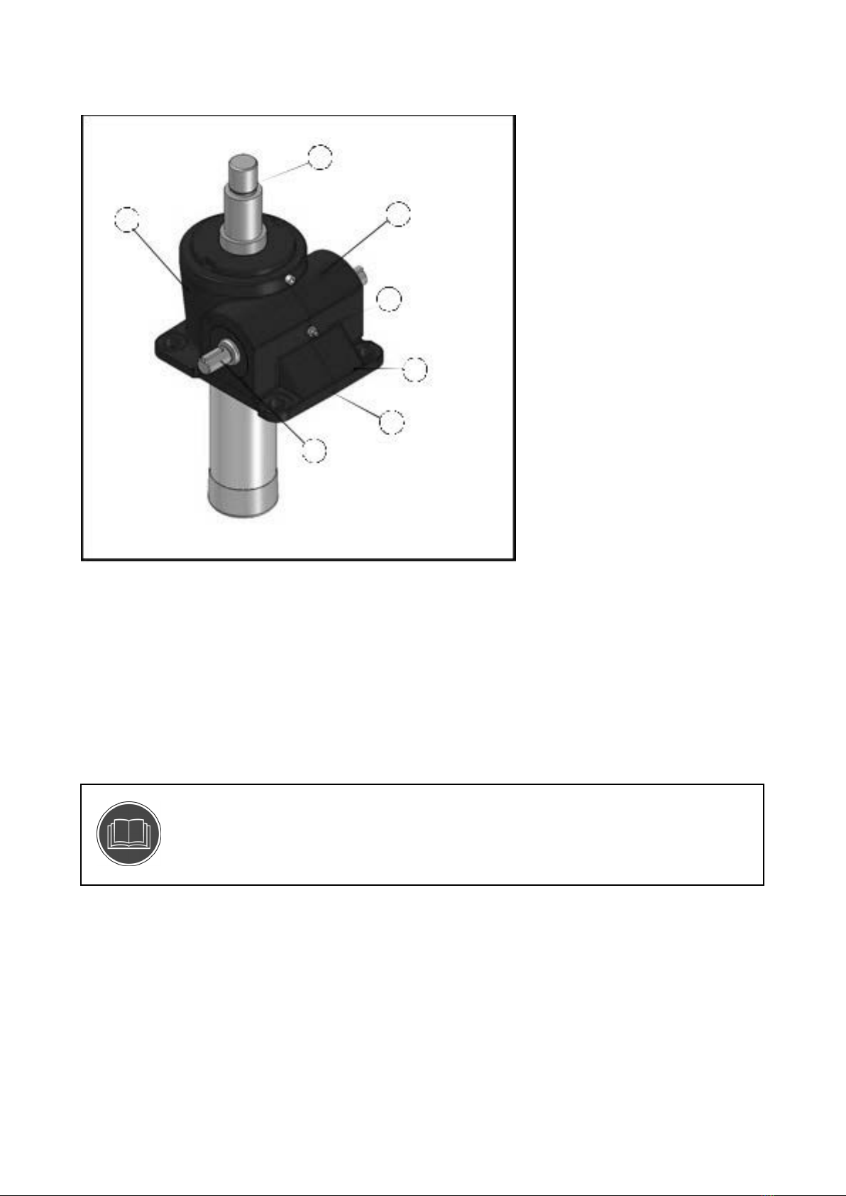
2
1. Trapezoidal lifting screw
2. Thrust and radial bearings
3. Grease with EP-additive
4. Housing of nodular cast iron
5. Alkyd paint 85 micron thickness in RAL 5009
6. Worm screw hardened and ground
7. Worm wheel of centrifugally cast tin bronze
8. Bellows in PVC or steel (Not shown. Other materials are available upon request)
1.1.3 System overview
1.1.4 Drawings/layouts
NOTE: ABOUT DRAWINGS/LAYOUT!
Drawings/layouts for your specific application, may where appropriate, also be
supplied from our website (if appropriate also including technical documentation from
subcontractors).
1
2
3
4
5
6
7

3
1.2 TECHNICAL DATA
1.2.1 Identification
Product type BD
Serial number See Product Sign
Yearofmanufacture See Product Sign
Compression load / Tension load (kN) See Product Sign
Load Case (Euler I, II or III See Product Sign
Single start spindle:
Product size 27 40 58 66 86 100 125 200
Max capacity (kN) 10 25 50 150 200 300 500 1000
Ratio (L) 9:1 7:1 6.75:1 7:1 7:1 7:1 7.5:1 12:1
Starting torque (Nm) 6 23 55 210 320 640 1280 2235
Ratio (H) 27:1 30:1 27:1 28:1 28:1 28:1 30:1 36:1
Starting torque (Nm) 5 10 32 115 160 320 640 1335
Double start spindle:
Product size 27 40 58 66 86 100 125 200
Max capacity (kN) 8 20 40 120 160 240 400 800
Ratio (L) 9:1 7:1 6.75:1 7:1 7:1 7:1 7.5:1 12:1
Starting torque (Nm) 6 23 55 210 320 640 1280 2120
Ratio (H) 27:1 30:1 27:1 28:1 28:1 28:1 30:1 36:1
Starting torque (Nm) 4.8 10. 1 32.5 117 164 323 624 1265
1.2.2 External Electrical Power — Supply data
Connecting information regarding electric system.
Connecting voltage and number of phases See Product Sign
Frequency See Product Sign
Power See Product Sign
Motor Effect See Product Sign
Protection class See Product Sign
Classification of degree IK 08
The jack complies with IEC standards. The effect required depends on the load. For further information
contact AB Benzlers.
NOTE: ABOUT IK CODE!
IK code means the classification of degrees of protec- tion provided by enclosure for
motors against external mechanical impacts. IK 08 = Resistance against im- pacts with an
energy up to 5,00 J.

4
1.2.3 IP code, clear text
The IP Code (International Protection Rating) classifies the degrees of protection provided against the
intrusion of solid objects such as dust, accidental contact and water in electrical enclosures as defined in the
international standard IEC 60529. An IP Code consists of the letters IP followed by two digits and an optional
letter. The first digit indicates the level of protection that the enclosure provides against access to hazardous
parts and the ingress of solid foreign objects. The second digit indicates the protection of the equipment
inside the enclosure against harmful ingress of water.
See the motor manual for the IP Code of the connected motor. The table below shows the IP Code of the most
common used motors.
Motor types IP Code Protected against Details
M2V A M3A A IP 55 Dust
Water jets
Ingress of dust is not entirely pre- vented,
but it must not enter in suf- ficient
quantity to interfere with the satisfactory
operation of the equip- ment; complete
protection against contact. Water
projected by a nozzle against enclosure
from any direction shall have no harmful
effects.
NOTE: ABOUT IP CODE FOR THE JACK!
The IP code for the jack is different from the motor’s IP code and only jacks in stainless
execution (not standard) are allowed to operate in a moist environment.
1.2.4 Environmental conditions and limits
All Series BD units are provided with protection against normal weather conditions.
The lifetime of the jack are 200 operating hours (minimum).
Where units are to operate in extreme conditions, or where they are to stand for long periods without running,
e.g. during plant construction, consult AB Benzlers so that arrangements for adequate protection can be
made.
• Intheeventthatequipmentistobeheldinstoragesee”Storingandprotecting”onpage29.
NOTE: ABOUT OTHER CONDITIONS!
For other conditions consult Benzlers. Being an inter- national company, we are able,
through our own sub- sidiaries and active agents, to give the optimum- solution, on a local
basis.

5
1.3 PRODUCT MARKING
Figur2.Productsign–Generaldescription(type”BD”asanexample):
1. Line 1: Productcode
2. Line 2: –
3. Line 3: Exampel with
– motor: Power (kW), Voltage (V) Frequency (Hz), Pos. of terminal box, Gap at delivery SHM
– IEC motor flange: Max running power at 20% degree of utaliza- tion, IEC size, Gap at delivery SHM
– Free input shaft (Reducer only): Max running power at 20% de- gree of utalization, Gap at delivery SHM
4. Line 4: Lubrication = Lub, Total weight of the unit (Kg)
5. Line 5: Order-number and sub-number of the order position, Manufacturing- year
Product examples:
Motor
IEC motor flange
Free input shaft
1.3.1 Product sign

6
NOTE: ABOUT MOTOR CONNECTIONS!
Formoreinformationaboutmotorconnectionsee”MotorConnections”onpage26.
NOTE: ABOUT STARTING TORQUE AND LOAD CASES!
Formoreinformationaboutstartingtorqueandloadcasessee”Options”onpage6.
1.3.2 Option – extra sign according to ATEX directive
Jacks ordered to comply with EU directive 94/9/EC ATEX 100a have an extra sign.
Figur 3. Extra sign according to ATEX directive
NOTE: ABOUT ATEX!
AB Benzlers must be consulted in advance to adapt the jack to comply with 94/9/EC (ATEX
100a). The jack will be marked with an extra sign according to ATEX directive. For more
information see our Product Catalog.

7
1.3.3 Understanding ATEX Directive - Markings
NOTE: ABOUT ANY OTHER EQUIPMENT FITTED TO THE SCREW JACK!
Motors, gears, couplings, or any other equipment fitted to the screw jack unit must also
comply with this directive.
If the screw jack unit is supplied with a motor (or any other equipment fitted) it is important
to check that the nameplate corresponds with the classification of the potentially explosive
atmosphere in which the unit is to be installed.
CAUTION: RISK OF MACHINE DAMAGE!
Only jacks ordered to comply with 94/9/EC (ATEX 100a) and marked with an ATEX sign are
allowed to be used in an explosive environment.
The jack will be typically marked as shown
Figur 4. ATEX marking
The maximum surface temperatures for the jack are 200 °C (T3) and 135°C (T4).
CAUTION: RISK OF MACHINE DAMAGE!
Standard configuration is not suitable for these temperatures.
The protection type in areas with combustible dust and in hazardous areas is ‘ck’ where ‘c’ stands for
protection by constructional safety (couplings and gear drives) and ‘k’ stands for protection by liquid
immersion (gears).
GD means that the jack is suitable for gas and dust explosive atmospheres.
Group II means areas with potentially explosive atmospheres (except mines and firedamp areas).

8
For Category 2 and Category 3 see table below.
Cat Design of
Safety
Design
Requirements
Application Zone of Use
2 High level of
safety
Safe with frequently
occu. Disturbances
or with an
operating fault
Where explosive
atmospheres are
likely to occur
Zone 1 - An atmosphere where
a mixture of air and flammable
substances in the form of gas, vapor
or mist is likely to occur in normal
operation occasionally.
Zone 21 - An atmosphere where a
cloud of combus- tible dust in the air
is likely to occur in normal operation
occasionally.
3 Normal level
of safety
Safe in normal
operation
Where explosive
atmospheres are
likely to occur
infrequently and be
of short duration
Zone 2 - An atmosphere where
a mixture of air and flammable
substances in the form of gas, vapor
or mist is not likely to occur in nor-
mal operation but, if it does occur, will
persist for only a short period.
Zone 22 - An atmosphere where a cloud
of combus- tible dust in the air is not
li- kely to occur in normal operation but,
if it does oc- cur, will persist for only a
short period.

9
2 USE OF THIS MANUAL
2.1 GENERAL INFORMATION ABOUT THIS MANUAL
The manual contains operating and safety instructions.
Carefully study the manual and check that the manual is constantly available to the staff concerned. The
instructions apply all types of work, the machine as well as immediate surroundings around the machine.
Serious personal injuries and machine damages may occur if the information is not attended to.
Consider all the danger-, warning-, caution- and note- signs mentioned in the manual.
• Considerthatalltypesofelectricequipmentmaybelive.
• Duringserviceandmaintenance:switchoffthemachineandmakesurethattheelectricalsupplyisoff
(safety and main switches locked). Supervision may be carried out by an operator. Remaining service may
be performed by qualified service staff only.
Consideration shall be taken to the local restrictions inside the factory.
2.2 IMPORTANT INFORMATION ABOUT THIS MANUAL
The following is compulsory:
• Themanualtogetherwithsimilarusefuldocumentsshallbekeptduringtheentirelifeoftheequipment.
• Thismanualtogetherwithsimilarusefuldocumentsshallbeconsideredpartoftheequipment.
• Theinformationinthemanualshallbeupdatedwhenthemachineownermakescompletionsorother
modifications of this equipment.
• Incaseofownerexchangethemanualshallbeenclosedtothenewowneroruseroftheequipment.
• Incaseofrebuildingorreconstructionanewriskanalysisshouldbeestablished.
All changes shall be approved by the machine owner.
2.3 TARGET GROUP FOR THIS INFORMATION
The manual shall be used for information about safety for all staff, who perform or will perform any kind of
work near the screw jacks, as an example:
• Installationandmaintenancepersonnel
• Operators
• Cleaners,etc.
2.3.1 Demands on personnel
Information about instructions in this manual. Site/location of instructions.
NOTE: ABOUT OPERATORS!
Operators and other staff are only allowed to handle that part of the screw jack for which
they are trained. The operators shall be provided with all necessary information about
training and about pumping and translating forces.
The place shall be clearly marked and this manual shall be available in direct connection to the other
instructions of the screw jack.
2.3.2 Procedure for revision and amendment
If necessary and especiallity according to issues about safety the content of this manual may need to be
updated at any time.
On these occasions, it is especially important that this manual is replaced with a new updated manual and
that the old manual is collected and archived /discarded.

10
3 DESCRIPTION OF FUNCTION
3.1 OVERALL
BD is a screw jack with single or double start trapezoidal lifting screw available with translating lifting screw.
Figur 5. BD
It is available in 8 sizes as standard.
This type is the most frequently used screw jack, competively priced.
NOTE: ABOUT STOP NUT!
BD is available with a stop nut. If you chose not to use the stop nut another security feature
must be included in the system.
The jack is used to push, pull, lift, lower and position loads of anything from a couple of kilograms up to one
hundred of tons with good precision and consistency.

11
3.1.1 Control devices
Control devices for the jack shall be designed according to the description below:
• Controldevicesforsettingpowerdrivenjacksinmotionshallbeofthehold-to-runtype.
• Controldevicesforpowerdrivenjacksshallbeprotectedagainstunintentionaloperation.
• Thedirectionofmovementcausedbythecontroldeviceshallbeidentiedinadurable,unambiguousand
easily recognisable manner.
• Thedirectionofmotioncanbeidentiedbysymbolsorwords.Theidenticationcanbeattachedtothe
control device itself or immediately alongside it.
NOTE: ABOUT CONTROL DEVICES!
Control devices are not included at standard delivery.
WARNING: CRUSHING RISK!
This protection prevents the possibility of pinched fingers or chruched hands, which can
lead to permanent injury.
WARNING: RISK OF ENTANGLEMENT!
This shaft protection prevents, for example, loose clo- thing or similar to entangle itself in
the shaft, which can lead to permanent injury.
DANGER: CRUSHING RISK!
This safety component prevents the lifting screw from being able to run out of the jacks
house, which, if a person/persons standing under the jack, can lead to instant danger to life.
Moreinformation,see”Stopnut(SM)”onpage12.

12
3.2 OPTIONS
NOTE: IMPORTANT INFORMATION ABOUT ALL OPTIONS!
For the up-to-date configuration of your Srew Jack, see the product code on the product
sign that is mounted on the jack.
3.2.1 Stop nut (SM)
Stop nuts can be fitted to all screw jacks, both above and below the main body.
These must be included when there is an inherent risk of over travel resulting in the spindle becoming
disengaged from the worm thread.
Figur 6.
6. Stop nut
7. Protection tube
8. Tube sleeve

13
3.2.2 Stop nut (SM) + Limit Switch (LS)
All jacks can be supplied with limit switches to suit most applications. Standard is two limit switches and one
stop nut. Upper/lower limits can be mounted on the protection tube. Adjustable limits are also available on
request.
Figur 7.
1. Stop nut
2. Carrier
3. Limit switch
3.2.3 Locked against rotation – two options are available:
– LR - Locked Against Rotation (Tube)
– LRK - Locked Against Rotation (Key)
NOTE: IMPORTANT INFORMATION ABOUT THESE OPTIONS!
For applications where a load is to be raised/lowered and permanent fixing i.e. top plate/
clevis, is not prac- tical, the spindle must be prevented from rotating.
Combinations with other options are restricted.

14
3.2.4 LR - Locked Against Rotation (Tube)
Protection tube manufactured in box section mild steel. Spindle end complete with nut
(sized to suit box section).
Figur 8.
1. Gear housing
2. Locking nut
3. Locking assembly (size dependent variant 1)
4. Tube
5. Pin (size dependent variant 2)
3.2.5 LRK - Locked Against Rotation (Key)
Jack internals are modified to incorporate a rectangular key which engages in a precision keyway cut into the
spindle length. Primarily used in precision applications requiring minimal radial movement.
Figur 9.
1. Jack cover
2. Lifting screw
3. Key

15
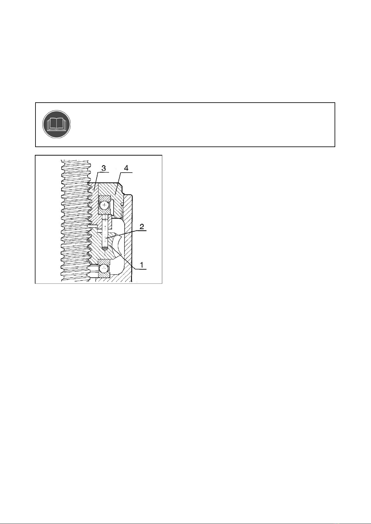
3.2.6 Safety Nut (SHM)
In certain applications the addition of a safety nut may be required. The object of the above is to prevent the
load collapsing in the event of the
lifting nut thread failing.
NOTE: IMPORTANT INFORMATION ABOUT THIS OPTION!
Load direction important!
Combinations with other options are restricted.
Monitoring of the safety gap (s) between the spacer (2) and the safety nut (1) gives an indication of the
intermediate wear.
NOTE: THE SAFETY GAP MUST BE CHECKED REGULARY!
When the safety gap reaches zero the thread in worm wheel has reached its wear limit
and requires chang- ing. In applications where the safety nut is inacces- sible, electro/
mechanicalswitchesareavailabletoindicatemaximumwear,moreinformation,see”Mea-
suringofthreadwearinrunningnut”onpage35.
Figur 10.
1. Safety nut
2. Spacer
3. Worm wheel
16
3.2.7 Antibacklash (ABL)
Where the loading on a screw jack can be in both tension and compression and the spindle backlash is
critical, units can be supplied with a Back-lash Eliminator comprising of a modified worm wheel fitted with a
secondary nut, allowing contact on both face and flank of driving thread.
Backlash 0.0l-0.05 mm - During operation excessive backlash can be removed by adjustment of the top cover.
The nuts are separated by a pre-determined gap to eliminate the adjustment of the backlash
eliminator when drive thread width has been reduced by 25%.
NOTE: IMPORTANT INFORMATION ABOUT THIS OPTION!
Combinations with other options are restricted.
Figur 11.
1. Worm wheel
2. Dowel pin
3. Adjusting nut
4. Jack cover
This manual suits for next models
8
Popular Jack manuals by other brands


TradeQuip
TradeQuip 2051T owner's manual

Mega
Mega FMG-300 Operation and maintenance instructions

ATD Tools
ATD Tools ATD-7384W owner's manual

ELECTRODRIVE
ELECTRODRIVE Tug Tough 10T operating manual

Tractel
Tractel tirfor TU-8 Operating and maintenance instruction

Bulldog Security
Bulldog Security Velocity Series instructions


