CHIEF Air Jack User manual

ChiefAir Jack
Users Manual
2006 © Chief Automotive Technologies, Inc.


Chief’s Limited One-Year
Warranty & Liability
CHIEF'S LIMITED ONE-YEAR
WARRANTY & LIABILITY
Chief Automotive Technologies, Inc. warrants for one year from date of installation
and/or purchase any of its products which do not perform satisfactorily due to defect
caused by faulty material or workmanship. Chief’s obligation under this warranty is
limited to the repair or replacement of products which are defective and which have not
been misused, carelessly handled, or defaced by repair or repairs made or attempted by
others.
CHIEF AUTOMOTIVE TECHNOLOGIES, INC. DOES NOT ASSUME
RESPONSIBILITY FOR ANY DEATH, INJURY OR PROPERTY DAMAGE
RESULTING FROM THE OPERATOR’S NEGLIGENCE OR MISUSE OF THIS
PRODUCT OR ITS ATTACHMENTS. CHIEF MAKES NO WRITTEN,
EXPRESS OR IMPLIED WARRANTY WHATSOEVER OF MERCHANTABIL-
ITY OR FITNESS FOR A PARTICULAR PURPOSE OR OTHERWISE
REGARDING THE EQUIPMENT OR ANY PART OF THE PRODUCT OTHER
THAN THE LIMITED ONE-YEAR WARRANTY STATED ABOVE.

CHIEF AIR JACK
USERS MANUAL
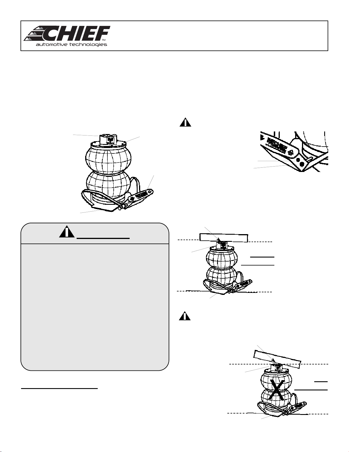
The Chief AirJack (see Figure 1) is a lightweight lifting
tool that is easy to use. The device is ideal for tire and
alignment shops, body shops, and service garages that fre-
quently need to elevate the front end, rear end or side of
a vehicle for tire removal / installation.
Read all of the instructions and warnings provided before
attempting to operate the Chief Air Jack. Also, make sure
all personnel who are to use the Chief Air Jack are familiar
with its operation.
To operate the Chief air jack:
1. Position vehicle on solid flat surface and engage its
parking brake.
2. Block vehicles front and rear wheels.
3. Attach air hose to air jack and position jack on solid flat
surface directly below structural component to be lifted.
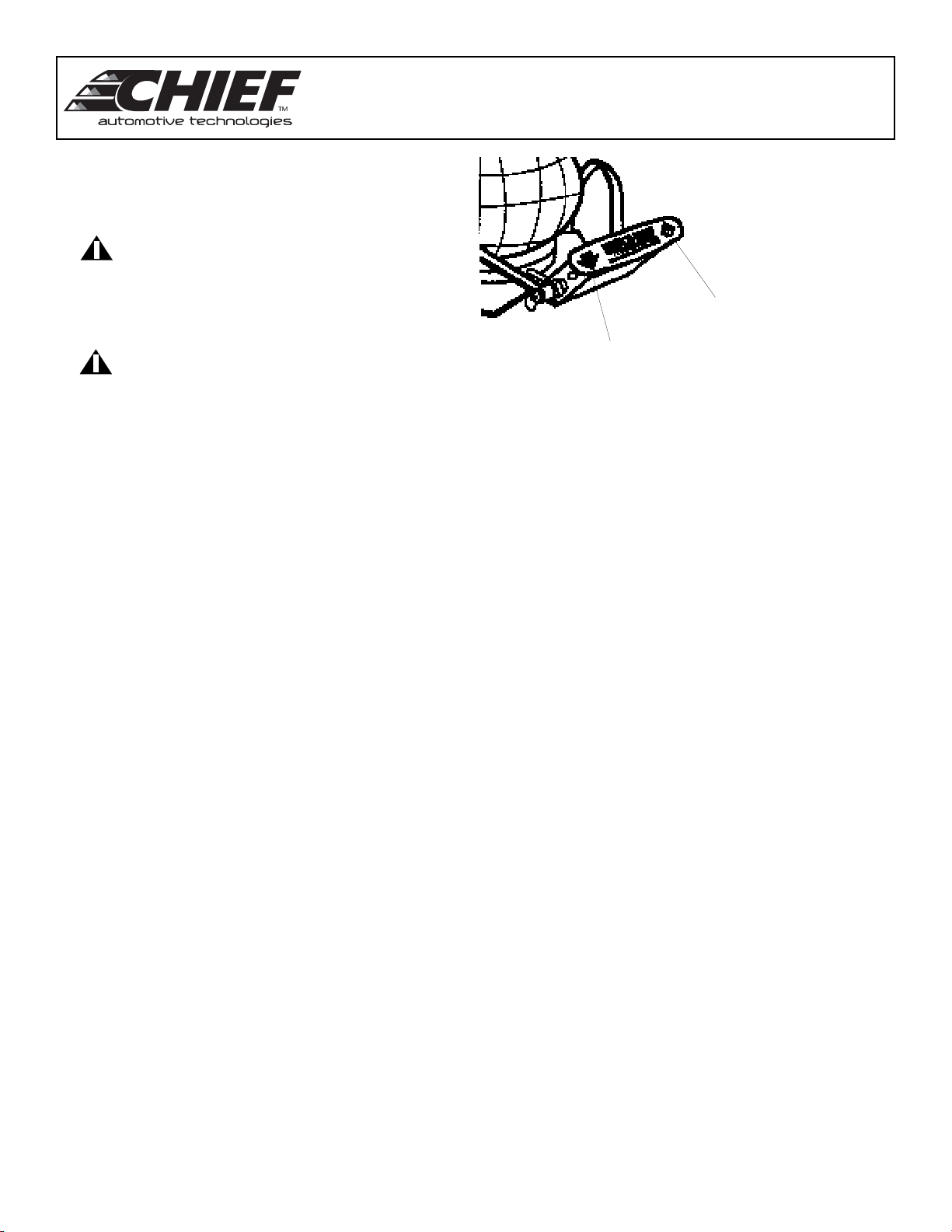
NOTE: • Air inlet on control base handle accepts 1/4
inch NPT fitting. (See Figure 2.) Add a
fewdrops of pneumatic tool oil to air inlet
monthly.
• Position handle assembly for easy access.
WARNING! DO NOT remove brass plug from
handle assembly.
4. Check the intended lifting point on the structural compo-
nent. This location must be parallel with base of air jack
and lift pad. (See Figure 3.) If it is not parallel (see Figure
4), the load may drop suddenly, creating a potential for
severe injury or death.
WARNING! To prevent slippage, lifting point on
structural component must always be parallel
with base of air jack and lift pad.
Figure 2
Figure 1
Figure 3
Figure 4
1
WARNING!
• Visually inspect air jack prior to each use.
DO NOT use if scars, abrasions, rips,
punctures are detected in the air bag.
• Always wear safety glasses.
• DO NOT use as a jack stand.
• Avoid contact with petroleum based
products or chemicals of any kind.
• Use jack stand on firm level surfaces only.
• Avoid sharp objects that may puncture
air bag.
• DO NOT use near open flame, sparks, or
temperatures exceeding 120° F (49° C).
• Maximum air pressure, 105 PSI (7.24 Bar) .
• Maximum load, 2 ton (1800 kg.)
Handle
Assembly
Base
Lift Pad Top Plate
Air Inlet
Brass Plug
Lifting Point On Structural Component
Base
Parallel
Alignment
Lift
Pad
Lifting Point On Structural Component
Base
Non
Alignment
Lift
Pad

CHIEF AIR JACK
USERS MANUAL
2
4. To use the air jack, position both hands on handle
assembly. Press ‘green’ arrow (right side arrow - see
Figure 5) and inflate bag slightly to engage lift pad
with lifting point on structural component.
WARNING! Lift load from lift pad only. Lifting from
top plate will damage air jackand cre-
ate an unsafe condition.
5. Press ‘green’ arrow again to elevate structural com-
ponent to desired height.
WARNING! • DO NOT lift higher than needed.
• DO NOT over inflate.
6. To deflate the air jack, push the ‘red’ arrow.
NOTE: If the air hose has been removed from the air
jack, press either the ‘red’ or ‘green’ arrow to
deflate.
Figure 5
Green
Arrow
‘Up’
Red
Arrow
‘Down’

CHIEF AIR JACK
USERS MANUAL
Parts Information
To order replacement parts for the Chief Air Jack,
call Chief Automotive Technologies, Inc. 800-445-
9262. If located outside the United States, contact
an authorized ChiefAutomotive Technologies, Inc.
representative. Refer to parts illustration and parts
list below.
1 CJ2200 Base
2 CJ2201 Lower Air Ring
3 CJ2202 O Ring (Bag Seal) 5.75
4 CJ2203 Air Bag
5 CJ2204 Center ring
6 CJ2205 Upper or Lower Bag Ring
7 CJ2207 Lower Plate Mtg. Bolts 1/4 20 x 1 1/4
8 CJ2208 Top Plate
9 CJ2209 Top Plate Mtg. Bolts 1/4 20 x 3/4
10 CJ2211 Rubber Washers
11 CJ2212 Jack Pad
12 CJ2213 Mtg. Bolts 3/8 16 x 7/8
13 CJ2217 Inner Member No. 1
14 CJ2218 Inner Member No. 2
15 CJ2219 Inner Member No. 3
16 CJ2220 Inner Member No. 4
17 CJ2221 Jack Pad Mtg. Bolt 3/8 16 x 2 1/4
18 CJ2223 Lock Ring
19 CJ2225 Air Filler Tube
20 CJ2226 Valve Block
21 CJ2227 Valve Block Mtg. Bolt 5/16 18 x 5/8
22 CJ2228 Handle
23 CJ2229 Roll Pin 5/16 x .187
24 CJ2230 Valve Body
25 CJ2231 Valve Stem
26 CJ2232 Valve Lock Cap
27 CJ2233 Valve Spring
28 CJ2234 O Ring .625
29 CJ2235 O Ring .250
30 CJ2236 O Ring .3/32 I.D. Teflon
31 CJ2237 Pressure Relief Valve
32 CJ2238 1/8 NPT Brass Allen Plug
33 CJ3101 WARNING Label
34 CJ3102 Chief Label, up / down arrows
35 CJ3103 Chief Label, Logo
Ref. Part No. Description
3
Chief Air Jack
W ARNING!
DO NOT Over Inflate.
DO NOT use as a jack stand.
Maximum pressure is 105psi.
Maximum load is 2 ton. Field
Replacement
Parts in
Shaded
Areas Only.


P.O. Box 1368
Grand Island, Nebraska 68802-1368
Phone: 308/384-9747
Fax: 308/384-8966
www.chiefautomotive.com
Form CAJ (Rev. 12/06)
Part No. 091899
Chief reserves the right to alter product specifications
and/or package components without notice.
Table of contents