Berchtold Podo-Q User manual

OPERATION MANUAL
PodoQPODIATRY DRILL WITH
BRUSHLESS VACUUM TECHNOLOGY
MADE IN
GERMANY
IMPORTANT:
Please read these instructions, especially the sections titled
“Dismantling the Handpiece” and “Burr Clutch Service”
You may also wish to refer to the Berchtold handpiece refer to the instructional
video located in the Product Videos section of our website or feel free to contact our
Service Department on 1800 33 4142.


INDEX
2 Technical Data
2 Safety Instructions
3 Main Features & Controls
3 Touch Pad Button Functions
3 Touch Display Functions
4 Operational Instructions
4 Programming Memory Slots
4 Hints & Troubleshooting
5 Changing the Dustbag
6 Touch Screen Display Fault Analysis
6 Warranty Details
7-10 Dismantling the Handpiece
11-13 Burr Clutch Service
14 PodoQ Handpiece Dismantling Video
1

2
Measurements: 290mmW x 80mmH x 250mmD
Equipment: Main Control Box, Micro-Motor Handpiece,
Vacuum/Power Hose, Dustbags,
Mains Power Lead, Operating Instructions
Total Weight: 2.4 kg
Power: 240V
Warranty: 36 Months (Return to Base)
DO NOT use bent or damaged mandrels and burrs (tools).
Only use quality tools which have a shaft diameter of 2.35mm (some inferior tools may have undersized
shafts which may slip and damage the Handpiece).
To reduce any chance of overheating ensure clearance of at least 25mm around all sides of the
Main Control Box. Ensure the ventilation slots in the Main Control Box are clear of any blockage.
Ensure no liquids enter the Main Control Box or Handpiece.
DO NOT clean the the Main Control Box with an alcohol based cleaner.
Only use an alcohol-free surface wipe (eg: Clinell).
The Main Control Box can only be opened by authorised service technicians.
Unauthorised opening of Main Control Box will negate the Manufacturers Warranty.
Do not operate the PodoQ Drill in extremely hot or very damp conditions.
Prior to dismantling the handpiece for cleaning, it is imperitive that you read the section titled
“Dismantling the Handpiece” on Pg 7. Failure to do so may result in damage that will NOT be
covered under warranty.
Technical Data
ARTG#: 161350
Handpiece Weight: 140 g
Noise Level: 62dB
Safety Instructions Please ensure the following are strictly adhered to:
Touch Pad Touch Screen Dustbag Compartment
Power Socket for Handpiece
External LED Light Connection
(not available in Australia)
Fuse Housing
Power On/Off
Rocker Switch
Mains Power Connection

25000
rpm
1 2 3
3
1. Start/Stop Button
2. Burr Speed Control Slider
3. Suction Stop/Stand-by Button
4. Vacuum Level Switches
5. External LED Light Switch (not available in Australia)
6. Burr Rotation Switch
7. Memory Buttons
8. Burr Speed Indicator
9. Dustbag Compartment (behind vacuum hose face plate)
10. Handpiece On/Off Switch
Main Features & Controls 8. 9.
10.
1. 3. 4. 5. 7.
6.
2.
Touch Pad Button Functions
Start/Stop Button
Starts/Stops selected burr speed and
direction, and vacuum suction.
Suction Stop/Stand-by Button
Stops suction and activates Stand-by
Mode. Hold button for 4 seconds to
activate Stand-by Mode.
Suction Level Buttons
Selects Low, Medium or High vacuum suction.
Burr Speed Control Slider
Slide finger across to adjust Burr Speed
(5,000rpm-25,00rpm).
Touch Display Functions
Burr Direction & Size Indicator
Displays current Burr Direction and suitable
burr size for selected Burr Speed.
5,000-10,000 rpm Large Burr
10,000-20,000 rpm Medium Burr
20,000-25,000 rpm Small Burr
Burr Speed Indicator
Displays currently selected Burr Speed.
Suction Strength Indicator
Displays currently selected Vacuum
Strength (Low, Medium or High).
External LED Light Switch
(not available in Australia)
Burr Direction Button
Switches Burr Direction
clockwise/anti-clockwise.
Memory Buttons
Press to select saved preferred
settings. Refer to Pg 4 for instructions
on how to programme memory slots.

1. Connect the orange power lead into the back of the Main Control Unit.
2. Plug the main power lead into a power point and turn the power point on.
3. Ensure a Dustbag is fitted to the unit. Refer to Pg 5 for instructions on fitting a Dustbag.
4. Insert your selected Burr or Mandrel into the Handpiece, pushing it firmly into place. (The Burr Clutch will lock/unlock
automatically when the Handpiece is turned on/off).
5. Turn the Drill on by pressing the Power On/Off Rocker Switch at the rear of the unit.
6. Select the direction you wish to have the Burr/Mandrel travel (clockwise or anti-clockwise) by pressing the Burr
Rotation Button (No.6) located on the bottom of the touch screen.
7. Select the speed you wish the Drill to operate at by sliding the Burr Speed Control Slider (No.2). Slide from left to
right to increase speed, slide from right to left to decrease speed. The range is from 5,000rpm to 25,000rpm.
8. Select the Vacuum Strength level by pressing one of the three Suction Level Buttons (No.4).
9. Activate the operation of the unit by pressing the Handpiece On/Off Switch (No.10). Pressing it a second time
will de-activate the Handpiece.
Operational Instructions
Where numbers are listed (eg: No.1) refer to Pg 3 for Button clarification.
The Berchtold PodoQ features the option to save preferred working settings (i.e: Burr Direction, Vacuum Strength & Burr
Speed) and to access them at the touch of a button. Follow the steps below to programme the three Memory Slots
available:
1. Using the Burr Speed, Burr Direction and Suction Level Buttons, adjust the drill to function at your desired outcome.
2. Press and hold the Start/Stop Button (No.1).
3. Whilst holding the Start/Stop Button press the desired Memory Button (No.7) on the Touch Screen.
4. Your preferred setting will now be saved to the Memory Button you selected.
Programming Memory Slots
This is an electrically operated piece of equipment. Never allow liquid to come into contact with the Main
Control Unit, or the Handpiece.
Never put any liquid or lubricant in the Handpiece.
DO NOT allow the Vacuum System to draw liquid into the Handpiece.
If the Dustbag Full Warning appears on the Touch Screen Display and the Dustbag is not full
- This warning comes on when the vacuum airflow starts to diminish as a result of the Dustbag being full.
However, there may be a blockage caused by a build-up of nail dust and lint within the Handpiece air
cavity. A full disassembly of the Handpiece should identify any blockages.
(Please refer to your Dismantling the Handpiece Chart to help you disassemble and re-assemble the
Handpiece).
When using the Drill, you find the Burr or Mandrel stops spinning when pressure is applied to the foot being
sanded
- It is possible there is a build up of fine debris within the Burr Clutch. Refer to your Burr Clutch Service Chart,
remove and clean the Burr Clutch taking particular care to clean the inside of the Burr Clutch Assembly
(Remember: DO NOT use liquids or lubricants when cleaning these components).
If any other faults or issues arise that are not detailed in this document please contact our Service
Department on 1800 33 4142 .
Hints & Troubleshooting
4

When the Dustbag Symbol appears on the Touch Screen, the Dustbag should be replaced.
To do this:
1. Switch the unit OFF by pressing the Power On/Off Rocker Switch at the rear of the Main Control Unit.
Changing the Dustbag
5
5. Slide the new Dustbag onto the alloy Vacuum
Hose Exit Pipe. Ensure the two male pins of the
Dustbag connect into the female ports at the
rear of the Vacuum Hose Face Plate. This will
reduce the chances of the Dustbag coming
loose while the drill is in operation.
6. Finally, insert the now connected Dustbag into
the Dustbag Compartment and firmly press the
Vacuum Hose Face Plate back into the Main
Control Unit.
2. Pull the Handpiece Power Socket out from the
Main Control Unit. DO NOT REMOVE VACUUM
HOSE FACE PLATE UNTIL THE HANDPIECE POWER
SOCKET HAS BEEN REMOVED.
3. Gently pull the Vacuum Hose Face Plate (No.9)
out of the Dustbag Compartment
(the Dustbag should come out with it).
4. Remove the Dustbag from the alloy Vacuum
Hose Exit Pipe by pulling it free. Dispose of the
full Dustbag.

- Problem with Suction - Turn off unit via Main Power Switch at rear of unit
- Turn on unit via Main Power Switch at rear of unit
- Contact Briggate Medical if problem persists
- Handpiece Power Plug not connected properly
- Possible blockage in Handpiece
- Possible Handpiece motor failure
- Remove and insert Handpiece Power Plug
- Dismantle and clean Handpiece as specified in
sections titled “Dismantling the Handpiece” on
Pg 9 and “Burr Clutch Service” on Pg 11
- Contact Briggate Medical if problem persists
- Dustbag full
- Possible blockage in Handpiece
- Remove and replace dustbag
- Dismantle and clean Handpiece as specified
in sections titled “Dismantling the Handpiece”
on Pg 9 and “Burr Clutch Service” on Pg 11
- Hardware error - Turn off unit via Main Power Switch at rear of unit
- Turn on unit via Main Power Switch at rear of unit
- Contact Briggate Medical if problem persists
Touch Display Fault Analysis
If any other faults or issues arise that are not detailed in this document please contact
our Service Department on 1800 33 4142 .
Warranty Details
Briggate Medical Company Warrants this Berchtold PodoQ Podiatry Drill to be free
from Manufacturing defects for a period of 36 months from the date of purchase
which is considered to be the date of shipment from our premises.
Warranty does not cover any issues with “wear and tear” items such as worn or noisy
bearings, a blocked Handpiece or any other general maintenance issues.
It is imperative that you complete the Registration details sheet provided with your
new drill and return the document to us promptly.
No Warranty will be extended to unregistered equipment.
Packing, Handling and Delivery Charges are applicable on ALL Equipment and
Instrument Service and Repairs, irrespective of the final Invoice Value of such
Service or Repair.
Damage resulting in failure to comply with instructions given in this manual or as the
result of mis-use will NOT be covered under Warranty.
6
Error Symbol Cause Solution
Dustbag
Handpiece
Vacuum Motor
Hardware

Hold the Main Alloy Body of the Handpiece in one hand, then
unscrew and remove the Alloy Nose Cone.
Then unscrew and remove the Burr Clutch Housing.
Main Alloy Body Knurled Locking Nut
On/Off Switch Assembly
Alloy Nose Cone
Vacuum Hose
Burr Clutch Housing Micro-motorBurr Clutch Assembly
Step 1
Step 2
Hold the Main Alloy Body of the Handpiece in one hand, then
unscrew and remove the Alloy Nose Cone.
Then unscrew and remove the Burr Clutch Housing.
Main Alloy Body Knurled Locking Nut
On/Off Switch Assembly
Alloy Nose Cone
Vacuum Hose
Burr Clutch Housing Micro-motorBurr Clutch Assembly
Hold the Main Alloy Body of the Handpiece in one hand, then
unscrew and remove the Alloy Nose Cone.
Then unscrew and remove the Burr Clutch Housing.
Main Alloy Body Knurled Locking Nut
On/Off Switch Assembly
Alloy Nose Cone
Vacuum Hose
Burr Clutch Housing Micro-motorBurr Clutch Assembly
7
Dismantling the Handpiece
Summary of Parts
A unique feature of the Berchtold handpiece is it’s ability to be completely dismantled, cleaned, and re-built.
To ensure optimal performance of your Berchtold handpieces we suggest that this be performed every 2-3 weeks.

Once the Main Alloy Body has been unscrewed, slide it away from the Knurled
Locking Nut and the Micro-motor will be exposed.
Once the nose cone and Burr Clutch Housing have been removed, hold the
Main Alloy Body (which has the Micro-motor in it) in one hand and the On/Off
Switch Assembly and Vacuum Hose in the other hand.
Now gently unscrew ONLY the Knurled Locking Nut with your fingers.
DO NOT attempt to unscrew this by twisting the On/Off Switch
Assembly or Vacuum Hose. Unscrew ONLY the Knurled Locking Nut. Twisting the
On/Off Switch Assembly or Vacuum Hose will damage the three power pins.
MAKE SURE THAT THE VACUUM HOSE ASSEMBLY
DOES NOT TURN!
ONLY THE LOCKING NUT SHOULD TURN.
If you wish to now disconnect the Micro-motor from the Vacuum Hose On/Off
Switch Assembly, then do so by holding the Vacuum Hose and gently pulling
the Micro-motor from it.
DO NOT turn or twist the Micro-motor, On/Off Switch Assembly or
Vacuum Hose when doing this.
8
Step 4
Step 5
Step 6

To re-assemble the Handpiece, carefully align the three “male” pins on the
Micro-motor to the three receiving “female” pins in the On/Off Switch
Assembly and push the motor all the way on.
Slide the Main Alloy Body over the Micro-motor.
Screw the Main alloy body on by turning only the Knurled Locking Nut with your
fingers. DO NOT twist or rotate the Vacuum Hhose or On/Off Switch Assembly
while doing this as ANY rotational pressure placed on the three power pins may result
in them being damaged, bent, or broken which will negate your
warranty and you will incur the cost of a replacement micro-motor.
Step 6
To re-assemble the Handpiece, carefully align the three “male” pins on the
Micro-motor to the three receiving “female” pins in the On/Off Switch
Assembly and push the motor all the way on.
Slide the Main Alloy Body over the Micro-motor.
Screw the Main alloy body on by turning only the Knurled Locking Nut with your
fingers. DO NOT twist or rotate the Vacuum Hhose or On/Off Switch Assembly
while doing this as ANY rotational pressure placed on the three power pins may result
in them being damaged, bent, or broken which will negate your
warranty and you will incur the cost of a replacement micro-motor.
Step 7
Step 8
9

Then screw the Alloy Nose Cone onto the Main Alloy Body.
Your Handpiece is now complete and ready to use.
Should you have any problems or questions,
do not hesitate to contact
on
Melb. Metro 8586 7800
Toll Free 1800 33 4142
Before screwing the Burr Clutch Housing onto the Micro-motor, use a burr or mandrel to
push the Burr Clutch Assembly from it’s housing. Now hold the Handpiece vertically and
place the Burr Clutch Assembly into the Micro-motor ensuring the nylon slotted drive
coupling nestles comfortably onto the “T” bar drive on the motor. Then screw the Burr
Clutch Housing onto the Micro-motor.
Step 9
Then screw the Alloy Nose Cone onto the Main Alloy Body.
Your Handpiece is now complete and ready to use.
Should you have any problems or questions,
do not hesitate to contact
on
Melb. Metro 8586 7800
Toll Free 1800 33 4142
Before screwing the Burr Clutch Housing onto the Micro-motor, use a burr or mandrel to
push the Burr Clutch Assembly from it’s housing. Now hold the Handpiece vertically and
place the Burr Clutch Assembly into the Micro-motor ensuring the nylon slotted drive
coupling nestles comfortably onto the “T” bar drive on the motor. Then screw the Burr
Clutch Housing onto the Micro-motor.
Step 10
Step 11
10

11
Remove any burr or mandrel that may be in the Handpiece.
Hold the Main Alloy Body of the Handpiece in one hand, then
unscrew and remove the Alloy Nose Cone.
Wipe away any nail dust from the nose cone with a damp
(not soaking wet) paper towel. An alcohol/chlorhexidine
moistened towel is recommended.
Whilst still holding the Main Alloy Body of the Handpiece,
unscrew the Burr Clutch Housing.
Put the Handpiece down and pick-up the Burr
Clutch Housing.
Using the shaft of a burr or mandrel, push into the Burr Clutch
Housing and push the Burr Clutch Assembly out of the housing.
Clean the empty housing in the same way
as the nose cone.
Step 1
Step 2
Step 3
A unique feature of the Berchtold handpiece is it’s ability to be completely dismantled, cleaned, and re-built.
To ensure optimal performance of your Berchtold handpieces we suggest that this be performed every 2-3 weeks.
Burr Clutch Service

Put the shaft of the burr or mandrel into the Burr Clutch
Assembly and draw the Clutch Fingers and the three Roller
Bearings out of the Burr Clutch Assembly.
Ensure to do this step over a benchtop or flat surface as
the three Roller Bearings in the Burr Clutch Assembly will fall
out upon removal.
To clean these components use a clean paper towel to remove any nail dust
from the Clutch Fingers, Roller Bearings, and the exterior of the Burr Clutch
Assembly. Use a cotton tipped applicator to clean the interior of the Burr
Clutch Assembly.
DO NOT APPLY ANY OIL OR GREASE.
Clutch Fingers
3 x Roller Bearings Burr Clutch Assembly
To re-assemble, put the shaft of the burr into the three pronged Clutch Fingers.
Place the three Roller Bearings around the exterior of the Clutch Fingers
(they will settle into place) then, while holding the Roller Bearings onto the
Clutch Fingers, slide the assembled clutch back into the Burr Clutch Assembly.
Hold the fingers and rollers in the assembly and slowly draw the burr out.
Front view
Step 4
Step 5
Step 6
12

Pick up the handpiece and hold it vertically with the power lead down and
the top of the Micro-motor up.
Place the Burr Clutch Assembly (without the housing on it yet) on the top of the
Hand-piece and ensue the Nylon Slotted Drive coupling nestles comfortably
onto the “T” bar drive on the motor.
Now, lower the burr clutch housing over the burr clutch assembly and screw it
firmly (not tightly) into place over the Burr Clutch Assembly.
Nylon Slotted Drive
Screw th Alloy Nose Cone back onto the Main Alloy Body.
Step 7
Step 8
IMPORTANT NOTE:
Whenever you are screwing or unscrewing any part of the handpiece
ALWAYS ensure you are only holding metal sections in your hands.
This will ensure that you do not put any “twisting” pressure on the three
power connecting pins on the micro-motor.
13

S35-TS/PodoQ Handpiece Dismantling Video
Due to the unique style of the Handpiece on the S35-TS/PodoQ, it is extremely important
that the procedures listed in this document are followed. Failure to do so could damage
the Handpiece’s micro-motor which will not be covered under warranty.
In conjunction with this manual, we have produced a video that outlines this process to
further demonstrate it’s importance.
Head to the the “Product Videos” section at www.briggatemedical.com (located at the
top left of our home page) and scroll down to the video titled “Berchtold S35-TS Podiatry
Drill Demonstration”.
It is advised that any staff member who uses this drill is well aware of how to
self-service the Handpiece and should view this manual and/or the video online.
14

premier
R
kemdent R
Quality Drill Cosumables
Refer to www.briggatemedical.com for our full range of drill consumables available
from the following manufacturers:
Burrs:
Sanding Discs:
Mandrels:
BD369060
Style 369 060
Medium Bud
BD369080
Style 369 080
Large Bud
BD369050
Style 369 050
Small Bud
BR395
Flame
Style 395
BR396
Bud Medium
Style 396
BR397
Bud Small
Style 397
BD-BUD
PBS Premier
Bud
BD-BARR
PBS Premier
Barrel
BD-PEAR
PBS Premier
Pear

MADE IN
GERMANY
DELIVERY
FEES MAY
APPLY
5YEAR
WARRANTY
VIDEO
ONLINE
FOOT
CONTROL
MEMORY
240kg
960kg Static Hold
Patient Lift Capacity
55cm
Low Entry Height
5
Chair Position
Programmable
Memory
Year
Warranty
Anthracite
CONTACT BRIGGATE MEDICAL COMPANY FOR FURTHER INFORMATION & PRICING.

MADE IN
GERMANY
DELIVERY
FEES MAY
APPLY
5YEAR
WARRANTY
VIDEO
ONLINE
COLOUR
MATCHED
OP-CHAIR
AVAIL.
Year
Warranty
Baltic Blue
175kg
700kg Static Hold
Patient Lift Capacity
NO ongoing
service required
5
Proven Reliability
& Design
CONTACT BRIGGATE MEDICAL COMPANY FOR FURTHER INFORMATION & PRICING.

23-25 Lakewood Blvd
Braeside Vic 3195
Australia
Ph: (03) 8586 7800
Fax: (03) 8586 7888
www.briggatemedical.com
Other manuals for Podo-Q
1
Table of contents
Other Berchtold Medical Equipment manuals
Berchtold
Berchtold Operon D860 User manual
Berchtold
Berchtold Podo S60 User manual
Berchtold
Berchtold Operon D850 Guide

Berchtold
Berchtold ELEKTROTOM 530 User manual
Berchtold
Berchtold OPERON B 810 Guide

Berchtold
Berchtold OPERON B 810 Installation instructions
Berchtold
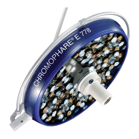
Berchtold CHROMOPHARE E 778 User manual
