Berchtold OPERON B 810 Installation instructions
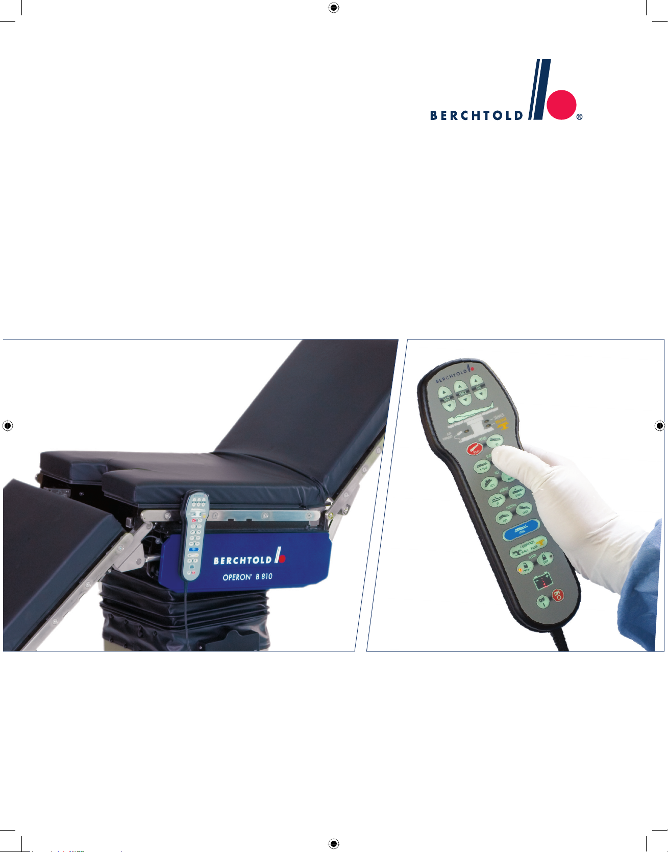
OPERON® B 810
INSTALLATION & OPERATING MANUAL

INSTALLATION AND OPERATOR MANUAL 70-000-0026
Related Publications:
OPERON B 810 Uncrating Instructions 60-000-0002
OPERON B 810 Service and Parts Manual 70-000-0027
This manual contains proprietary information of Berchtold Corp. It shall not be reproduced in whole or in part
without the written permission of Berchtold Corp.
ETL/CETL LISTED TO IEC 60601-1. MEDICAL ELECTRICAL EQUIPMENT
OPERON®IS A REGISTERED TRADEMARK OF BERCHTOLD CORPORATION.

OPERON B 810 SURGICAL TABLE
TABLE OF CONTENTS
TABLE OF CONTENTS
SPECIAL SAFETY INSTRUCTIONS.................................................................................................................. S-1
SAFETY SYMBOLS......................................................................................................................................... S-1
USE CONDITIONS........................................................................................................................................... S-1
PINCH POINTS................................................................................................................................................. S-1
CONTROL PENDANTS................................................................................................................................... S-2
LOAD CAPACITY............................................................................................................................................ S-2
PATIENT POSITIONING................................................................................................................................. S-3
OPERATION..................................................................................................................................................... S-4
TABLE MOVEMENT WITH PATIENT.......................................................................................................... S-4
ENVIRONMENTAL REQUIREMENTS.......................................................................................................... S-4
UNPACKING .................................................................................................................................................... S-4
CHECKS AND ADJUSTMENT ....................................................................................................................... S-5
RADIOLUCENT TABLE TOP AND PADS .................................................................................................... S-5
POWER SUPPLY.............................................................................................................................................. S-5
CLEANING AND DISINFECTION ................................................................................................................. S-5
ACCESSORIES DESIGNED BY OTHERS ..................................................................................................... S-5
WARNING LABELS ........................................................................................................................................ S-6
INSTALLATION INSTRUCTIONS......................................................................................................................1-1
ELECTRICAL POWER REQUIREMENTS......................................................................................................1-1
ENVIRONMENTAL REQUIREMENTS...........................................................................................................1-1
TOOLS REQUIRED...........................................................................................................................................1-1
UNPACKING .....................................................................................................................................................1-2
INSTALLATION................................................................................................................................................1-4
INSTALLING THE PADS..........................................................................................................................1-4
INSTALLING THE HEADREST................................................................................................................1-5
CHECKS AND ADJUSTMENT ........................................................................................................................1-5
SETTING THE TABLE LEVELS......................................................................................................................1-6
AC FUSES (MAINS AC) ...................................................................................................................................1-6
GENERAL INFORMATION..................................................................................................................................2-1
GENERAL DESCRIPTION ...............................................................................................................................2-1
RADIOLUCENT TABLE TOP AND PADS .....................................................................................................2-1
INTERCHANGEABLE HEADREST ................................................................................................................2-1
POWER SUPPLY...............................................................................................................................................2-2
FUSES.................................................................................................................................................................2-2
FLOOR LOCK SYSTEM...................................................................................................................................2-3
PRIMARY HAND PENDANT...........................................................................................................................2-3
HAND PENDANT OPERATION...............................................................................................................2-4
PRIMARY HAND PENDANT INDICATORS ..........................................................................................2-5
PRIMARY HAND PENDANT FUNCTIONS............................................................................................2-6
70-000-0026 Rev. 2
i

OPERON B 810 SURGICAL TABLE
TABLE OF CONTENTS
FOOTSWITCH (OPTIONAL) ...........................................................................................................................2-7
MANUAL FOOT PUMP....................................................................................................................................2-7
AUXILIARY HAND PENDANT ......................................................................................................................2-8
AUXILIARY CONTROL DRAWER ................................................................................................................2-8
OPERATING INSTRUCTIONS............................................................................................................................3-2
PINCH POINTS..................................................................................................................................................3-2
LOAD CAPACITY.............................................................................................................................................3-3
PATIENT ORIENTATION................................................................................................................................3-3
NORMAL ORIENTATION........................................................................................................................3-3
REVERSE ORIENTATION........................................................................................................................3-3
PATIENT POSITIONING..................................................................................................................................3-3
TABLE MOVEMENT WITHPATIENT...........................................................................................................3-4
OPERATION......................................................................................................................................................3-4
FUNCTION PRIORITY.....................................................................................................................................3-5
TABLE MOVEMENT LIMITS .........................................................................................................................3-5
SOFTWARE-CONTROLLED LIMITS......................................................................................................3-6
USER-CONTROLLED LIMITS.................................................................................................................3-7
HEADREST........................................................................................................................................................3-7
REMOVABLE LEG SECTION.........................................................................................................................3-8
FOOTSWITCH (OPTIONAL)...........................................................................................................................3-9
BACKUP INSTRUCTIONS....................................................................................................................................4-5
MAINTENANCE.....................................................................................................................................................5-1
PERIODIC MAINTENANCE............................................................................................................................5-1
CLEANING AND DISINFECTION..................................................................................................................5-2
STAINLESS STEEL SURFACES .....................................................................................................................5-2
CLEANING METHODS....................................................................................................................................5-2
CLEANING AGENTS .......................................................................................................................................5-2
REMOVING STAINS........................................................................................................................................5-2
APPLYING DISINFECTANTS.........................................................................................................................5-2
PAINTED SURFACES ......................................................................................................................................5-2
CONDUCTIVE ITEMS......................................................................................................................................5-2
HAND PENDANTS...........................................................................................................................................5-3
IMPORTANT TELEPHONE NUMBERS.........................................................................................................5-3
PARTS AND ACCESSORIES...........................................................................................................................5-3
Rev. 2 70-000-0026
ii

OPERON B 810 SURGICAL TABLE
TABLE OF CONTENTS
TABLE OF FIGURES
FIGURE S-1 MAXIMUM WEIGHT LOCATION........................................................................................ S-3
FIGURE S-2 PATIENT SAFETY WARNING LABEL ................................................................................ S-6
FIGURE S-3 PRODUCT IDENTIFICATION LABEL................................................................................. S-6
FIGURE 1-1 SHIPPING CONTAINER...........................................................................................................1-2
FIGURE 1-2 SHIPPING CLAMPS..................................................................................................................1-3
FIGURE 1-3 LOADING/UNLOADING RAMP..............................................................................................1-3
FIGURE 1-4 REMOVE TABLE FROM SKID...............................................................................................1-4
FIGURE 1-5 PAD SET.......................................................................................................................................1-4
FIGURE 1-6 LOCKING LEVERS...................................................................................................................1-5
FIGURE 1-7 HEADREST .................................................................................................................................1-5
FIGURE 1-8 CHAIR POSITION......................................................................................................................1-6
FIGURE 2-1 OPERON B 810 SURGICAL TABLE.......................................................................................2-1
FIGURE 2-2 BASE COMPONENTS POWER SUPPLY...............................................................................2-2
FIGURE 2-3 PRODUCT IDENTIFICATION AND FUSE INFORMATION LABEL...............................2-3
FIGURE 2-4 PRIMARY HAND PENDANT AND FOOTSWITCH CONNECTOR BOX.........................2-3
FIGURE 2-5 HAND PENDANT POWER-ON INDICATORS......................................................................2-4
FIGURE 2-6 PRIMARY HAND PENDANT INDICATORS.........................................................................2-5
FIGURE 2-7 PRIMARY HAND PENDANT FUNCTIONS...........................................................................2-6
FIGURE 2-8 FOOTSWITCH............................................................................................................................2-7
FIGURE 2-9 DEPLOYING THE FOOT PUMP PEDAL..............................................................................2-7
FIGURE 2-10 LOCKING THE FOOT PUMP PEDAL...................................................................................2-7
FIGURE 2-11 LOCATION OF AUXILIARY PENDANT AND DRAWER .................................................2-8
FIGURE 2-12 ACCESSING THE AUXILIARY HAND PENDANT KEYBOARD......................................2-8
FIGURE 3-1 PINCH POINTS...........................................................................................................................3-2
FIGURE 3-2 NORMAL TABLE ORIENTATION.........................................................................................3-3
FIGURE 3-3 REVERSE TABLE ORIENTATION ........................................................................................3-3
FIGURE 3-4 NORMAL PERINEAL POSITION...........................................................................................3-4
FIGURE 3-5 REVERSE PERINEAL POSITION...........................................................................................3-4
FIGURE 3-6 HEADREST .................................................................................................................................3-7
FIGURE 3-7 ALIGNING THE LEG SECTION FOR INSTALLATION ...................................................3-8
FIGURE 3-8 LEG SECTION............................................................................................................................3-8
FIGURE 3-9 ASSEMBLED LEG SECTION..................................................................................................3-8
FIGURE 3-10 FOOTSWITCH............................................................................................................................3-9
FIGURE 4-1. BACKUP SYSTEMS...................................................................................................................4-1
FIGURE 4-2. AUXILIARYHAND PENDANT ..............................................................................................4-1
70-000-0026 Rev. 2
iii

OPERON B 810 SURGICAL TABLE
TABLE OF CONTENTS
TABLE OF TABLES
TABLE 2-1. TECHNICAL DATA...................................................................................................................2-1
TABLE 3-1. SOFTWARE-CONTROLLED LIMITS ...................................................................................3-5
TABLE 4-1. OPERATOR TROUBLESHOOTING GUIDE ........................................................................4-2
TABLE 5-1. RECOMMENDED MAINTENANCE SCHEDULE................................................................5-1
Rev. 2 70-000-0026
iv
OPERON B 810 SURGICAL TABLE
SPECIAL SAFETY INSTRUCTIONS
SPECIAL SAFETY INSTRUCTIONS
- IMPORTANT -
THE SAFETY INSTRUCTIONS THAT FOLLOW APPEAR WITHIN THE MANUAL.
READ THEM CAREFULLY BEFORE OPERATING THE UNIT AND FOLLOW INSTRUCTIONS.
PINCH POINTS
SAFETY SYMBOLS
WARNING
WARNING — Cutting or crushing
injury may occur if any part of a patient
or staff member is caught in a pinch
point when the table is articulated.
WARNING
WARNING — Damage to the table or
object may occur if any foreign object,
accessory, clamp, etc., is in a table
pinch point when a table is articulated.
This manual uses special symbols to help alert you to
important safety information:
WARNING
This symbol identifies a WARNING. A
warning indicates that the procedures
in the following text involve actions that
could cause harm or death to an
individual if certain precautions are not
taken. The warning text always
provides specific information on what
you must do to avoid the risk.
CAUTION
This symbol identifies a CAUTION. A
caution indicates that the procedures in
the following text involve actions that
could cause damage to the equipment,
including the failure to operate. The
caution text always provides specific
information on what you must do to
avoid the risk.
NOTE
This symbol identifies a NOTE. A note
contains information that can help you
perform the procedure in the following
text more effectively.
Pinch points include, but are not limited to:
•Kidney elevator to seat channels
•Kidney elevator to seat top
•Kidney elevator to back section
•Back section to side shields
•Leg section to side shields
•Leg section to column shield
•Leg section to base cover
•Leg section to seat section
•Back section link to seat channel
•Column shields to base cover
•Side shields to column shields (in tilt)
•Floor feet to base
•Floor feet to floor
•Base to floor
USE CONDITIONS •Headrest to back section
WARNING
WARNING — POSSIBLE EXPLOSION
HAZARD: Do not operate the table in
the presence of flammable anesthetics.
The OPERON B 810 table is designed
for use in non-hazardous anesthetizing
locations.
This list is not all-inclusive because pinch points can
be created by the attachment of accessories. Always
check that the patient and staff are clear of pinch
points before and while the table is in motion. Refer
to Figure 3-1 for details.
70-000-0026 Rev. 2
S-1

OPERON B 810 SURGICAL TABLE
SPECIAL SAFETY INSTRUCTIONS
CONTROL PENDANTS
NOTE
NOTE — The primary hand pendant
can be configured for normal or reverse
patient orientation by pressing the
NORMAL or REVERSE buttons on the
pendant. This reverses all functions
except floor locking, table up/down, and
kidney up/down. Using the reverse
function also disables the chair
function.
WARNING
WARNING — The primary hand
pendant is configured for normal patient
orientation. If the patient is reversed,
the back function must be used to raise
or lower the patient's legs and the Leg
function must be used to raise or lower
the patient's back. Trendelenburg, tilt,
and slide functions are also reversed if
the patient is in reverse orientation.
WARNING
WARNING — The auxiliary hand
pendant is configured for normal patient
orientation. If the patient is reversed,
the Back function must be used to raise
or lower the patient's legs and the Leg
function must be used to raise or lower
the patient's back. Trendelenburg, tilt,
and slide functions are also reversed
with respect to the patient’s orientation.
WARNING
WARNING — The auxiliary hand
pendant functions will operate
regardless of whether the floor feet are
locked or unlocked. If the floor feet are
unlocked, the table may roll when the
manual pump is operated.
CAUTION
CAUTION — The auxiliary hand
pendant does not have the following
functions: flex, chair, return to level, or
slide. This pendant is intended to be
used along with the manual foot pump
for completing procedures, followed by
charging the batteries or servicing the
table.
LOAD CAPACITY
This table has a patient lifting and articulation capacity
of 600 lbs. (273 kg). Positioning and constraints are
discussed on page S-3. Do not exceed this maximum
load in service. See FIGURE S-1.
WARNING
WARNING — Overloading may result
in tipping of the table or failure of the
table sections to move. Do not exceed
the maximum load.
NOTE
NOTE — The use of some accessories
will put additional restrictions on
patient weight. Accessories provided
by Berchtold Corporation, when used
as intended, are designed to perform
safely with the patient loads for which
this table was designed. A Berchtold
Corporation accessory that puts
additional restrictions on patient
weight, when used as intended, will be
clearly labeled to indicate the
maximum allowed loads.
Rev. 2 70-000-0026
S-2

OPERON B 810 SURGICAL TABLE
SPECIAL SAFETY INSTRUCTIONS
DetachableLeg Section Seat
Section
Primary
Hand
Pendant
FloorFeet
Primary Hand
Pendant
Receptacle
Footswitch
Receptacle
Manual Foot
Pump
Located on this
end ofBase:
Power Entry Module,
Fuses, and Auxiliary
Hand PendantDrawer.
Back
Section Headrest
Kidney
Elevator
Warning
Label
Footswitch
In reverse orientation,the
patient’s pelvis mustnot extend
beyond the end ofthe BACK
Section for full slide capability
In normal orientation,the
patient’s pelvis mustnot extend
beyond the end ofthe SEAT
Section for full slide capability
FIGURE S-1 MAXIMUM WEIGHT LOCATION
WARNING
WARNING — Before positioning the
table, be sure the correct table
orientation is selected as indicated by
the NORM or REV indicator on the
primary control pendant. Improper
orientation will result in reverse
functioning and potential patient
injury.
WARNING
WARNING — Possibility of tipping:
If full slide forward is required, the
patient’s pelvis must always be located
over the seat section when in normal
orientation. Using full forward slide
while the patient’s pelvis is on the leg
section can impair table stability and
result in patient injury or equipment
damage.
WARNING
WARNING — The leg section may be
removed from the table. If it is left on
the table, use caution when raising the
leg section while the patient is in this
position.
PATIENT POSITIONING
WARNING
WARNING — POSSIBILITY OF
TIPPING: Table stability may be
compromised if patients are positioned
beyond the following limits:
Normal Patient Orientation
The patient's pelvis should not be
extended beyond the end of the seat
section. The patient’s legs may be
placed on a leg extension attached to the
end of the leg section.
Reversed Patient Orientation
The patient's pelvis should not be
extended beyond the back section. The
patient’s legs may be placed on a leg
extension attached to the end of the back
section.
Full articulation and full slide in either
direction can be safely achieved with a
600lb (273kg) patient if these steps are
followed.
70-000-0026 Rev. 2
S-3

OPERON B 810 SURGICAL TABLE
SPECIAL SAFETY INSTRUCTIONS
OPERATION
WARNING
WARNING— The table should always
be locked to the floor whenever a
patient is on the table or being
transferred to or from the table. This is
accomplished by extending the table’s
feet by activating the FLOOR LOCK
function. This table is not intended for
patient transport.
CAUTION
CAUTION — Storage of clamps,
accessories, etc., on the base cover may
result in damage to lift column shields
and prevent proper elevation or descent
of the table.
CAUTION
CAUTION — The footswitch’s
electrical connections are resistant to
fluid intrusion, but if fluid drainage is
anticipated, the footswitch should be
protected by wrapping it with a clear
disposable footswitch bag. This will
reduce the need to disinfect the
footswitch.
TABLE MOVEMENT WITH PATIENT
WARNING
WARNING — If the table needs to be
moved with a patient on the table, it is
very important to follow the following
instructions to prevent patient injury or
equipment damage.
WARNING
WARNING — The table should not be
used to transport a patient over a long
distance. This procedure is only meant
for repositioning the table within the
surgical suite.
WARNING
WARNING — Do not mount knee
crutches or leg holders to the headrest
side rail. The headrest should only be
used for supporting the head or feet. Do
not lean on the headrest. The headrest
has a weight limit of 25lbs.
WARNING
WARNING — Be sure that when
articulating the headrest, the locking
mechanism ends up properly engaged,
and not in between positions. The
headrest may move when load is applied
until the locking mechanism engages.
WARNING
WARNING —When releasing the
locking mechanism, support the
headrest, as it will fall freely if the
locking mechanism is not engaged.
WARNING
WARNING — Failure to securely lock
the leg section into place may result in
patient injury. Always check the
retention of the leg section upon
installation.
ENVIRONMENTAL REQUIREMENTS
WARNING
WARNING— The batteries are sealed
to prevent spilling of the acid
electrolyte. If punctured and contact is
made with the acid, flush with cold
water for 15 minutes.
WARNING
WARNING— Although the batteries
are sealed to prevent spilling, they are
vented to allow for normal out gassing.
Because of this, the table should not be
used in a room that has no ventilation
system.
CAUTION
CAUTION — The batteries contain
LEAD, and if replaced, need to be
recycled in accordance with local
environmental regulations.
CAUTION
CAUTION — Do not expose the table to
steam or heat sources, or place the table
where it may be exposed to unusually
high temperatures.
CAUTION
CAUTION — Allow the table to reach
room temperature prior to operation if
the table was exposed to excessively hot
or cold conditions during transport or
storage.
WARNING
WARNING — When using the table in
the vicinity of high-frequency surgical
equipment, such as cardiac
defibrillators, and cardiac defibrillator
monitors, refer to the manufacturers’
instructions to ensure compatibility
issues are considered.
UNPACKING
WARNING
WARNING — POSSIBILITY OF
INJURY: This table weighs
approximately 715 pounds (325 kg). At
least two persons are required to
remove the table from its shipping
container.
Rev. 2 70-000-0026
S-4
OPERON B 810 SURGICAL TABLE
SPECIAL SAFETY INSTRUCTIONS
WARNING
WARNING — POSSIBILITY OF
INJURY: Do not attempt to lift the table
by its top sections. Failure to follow
uncrating instructions in the order given
will result in difficulty in removing the
table from the skid and possible
personal injury.
CAUTION
CAUTION — Do not attempt to lift the
table by its seat section or side rails.
Do not allow the table to drop off the
ramp, as this can damage the casters.
WARNING
WARNING — POSSIBILITY OF
TIPPING: The table will roll freely with
the legs unlocked. At least two people
are required to roll the table down the
ramp.
POWER SUPPLY
WARNING
WARNING — Repeated breaker
tripping or fuse replacement may
indicate a ground fault or overload
condition. The table will not operate
reliably under these conditions, and
may be electrically unsafe. Do not use
the table until these conditions are
corrected.
CLEANING AND DISINFECTION
WARNING
WARNING — Unplug the power cord
before cleaning the table if cleaning
liquids will be located near the power
cord receptacle. Under no
circumstances should steam or
extremely hot water (over 150°F/66°C)
be used to disinfect or clean the table.
Elevated temperatures and unusually
high humidity will weaken the hydraulic
lines and result in failure of the
hydraulic system and increased leakage
currents. Do not attempt to clean this
table in automatic cart washing
equipment. Use of high-pressure water
guns could lead to an electrical
malfunction and must be avoided.
CAUTION
CAUTION — Failure to thoroughly dry
the surface after cleaning may result in
rust.
CHECKS AND ADJUSTMENT
WARNING
WARNING — Installation checkout is
necessary to ensure that handling
during shipment did not damage the
table.
RADIOLUCENT TABLE TOP AND PADS
CAUTION
CAUTION — The anti-static
properties of the table depend on the
use of the recommended mattress.
Compromise of the anti-static
properties could expose the patient or
OR personnel to an electrostatic shock.
It could also deliver a shock to the
table’s electronics that could damage
or destroy critical components.
CAUTION
CAUTION — Protect the top and
bottom surfaces from nicks and
scratches. Scratches more than 0.005
inches (127 microns) deep may appear
on x-rays. Damaged or scratched
panels should be replaced if x-ray
quality is affected.
ACCESSORIES DESIGNED BY OTHERS
Berchtold Corporation assumes no liability for table
performance when used with accessories designed by
others for use on Berchtold equipment, or damage
resulting to Berchtold equipment resulting from the
use of accessories designed by others.
70-000-0026 Rev. 2
S-5

OPERON B 810 SURGICAL TABLE
SPECIAL SAFETY INSTRUCTIONS
WARNING LABELS FIGURE S-2 shows the patient safety warning label
attached to the table. The label is located on the base
at the foot end.
Drawing 306651 Rev. 1
FIGURE S-2 PATIENT SAFETY WARNING LABEL
WARNING
WARNING — Always replace fuses
with fuses of the same voltage and
current rating. Failure to use the
correct fuse could cause a fire and
injury to the patient or OR
personnel.
FIGURE S-3 shows the product information label
attached to the top of the column on the head side of
the table. The product information label also contains
fuse replacement information.
FIGURE S-3 PRODUCT IDENTIFICATION LABEL
Product
Identification
Information
Fuse
Information
Rev. 2 70-000-0026
S-6
OPERON B 810 SURGICAL TABLE
INSTALLATION INSTRUCTIONS
INSTALLATION INSTRUCTIONS
These instructions provide the information necessary
to unpack and install the OPERON B 810 Surgical
Table.
ELECTRICAL POWER REQUIREMENTS
WARNING
WARNING — POSSIBLE
EXPLOSION HAZARD: Do not
operate the table in the presence of
flammable anesthetics. The
OPERON B 810 table is designed for
use in non-hazardous anesthetizing
locations.
NOTE
NOTE — This table has been designed
to be connected to circuits installed in
accordance with NFPA 70 — National
Electrical Code. The user should also
be familiar with NFPA 99 — Health
Care Facilities. Consult these
references if you have any doubt about
the compliance of the user’s
maintenance program or electrical
system with code requirements.
NOTE
NOTE — This table is classified as
Class 1, Type B equipment in its type
and degree of protection against
electrical shock.
NOTE
NOTE – The table can be factory
configured for 230 VAC operation
based on customer order requirements.
The modifications involve only
components associated with the AC
mains supply. The information below
describes only the 115 VAC
components. Refer to the Service
Manual (publication 70-000-0027) for
identification of the 230 VAC
components.
The Berchtold OPERON B 810 table is completely
battery-operated. It only requires AC power for
battery charging, but it may be operated directly from
AC power when necessary or desirable.
The table is provided with a 14-ft. (4.27 m), 16 AWG,
three-conductor power cord terminated with a hospital
grade, three-prong plug. Attachment of a plug of
alternate design, if required, is the responsibility of the
customer.
The OPERON B 810 contains two (2) 12V 28 Amp-
hour Sealed Lead Acid (SLA) batteries. The batteries
are connected in series to provide 24V for the table’s
electrical system. The batteries are fused to prevent
high discharge due to a power short. The charging
system is designed to allow the table to be connected
to AC indefinitely without overcharging or damaging
the batteries. Other than periodic charging, the
batteries do not require maintenance.
ENVIRONMENTAL REQUIREMENTS
WARNING
WARNING— The batteries are sealed
to prevent spilling of the acid
electrolyte. If punctured and contact is
made with the acid, flush with cold
water for 15 minutes.
WARNING
WARNING— Although the batteries
are sealed to prevent spilling, they are
vented to allow for normal out gassing.
Because of this, the table should not be
used in a room that has no ventilation
system.
CAUTION
CAUTION — The batteries contain
LEAD and, if replaced, need to be
recycled in accordance with local
environmental regulations.
CAUTION
CAUTION — Do not expose the table
to steam or heat sources, or place the
table where it may be exposed to
unusually high temperatures.
CAUTION
CAUTION — Allow the table to reach
room temperature prior to operation if
the table was exposed to excessively hot
or cold conditions during transport or
storage.
See “ENVIRONMENTAL REQUIREMENTS” in
Table 2-1 for the appropriate environmental conditions
for the OPERON B 810 table.
Store the table in a cool, dry place. Do not subject the
table to environmental conditions in excess of those
specified in Table 2-1.
TOOLS REQUIRED
The following tools are required:
•Level
•Angle indicator
•Tape measure
•11 & 14mm socket wrench
•Diagonal cutters
•Flathead screwdriver
•Pliers
70-000-0026 Rev. 2
1-1
OPERON B 810 SURGICAL TABLE
INSTALLATION INSTRUCTIONS
4. Check contents of smaller carton:
UNPACKING a. Primary Hand Pendant
WARNING
WARNING — POSSIBILITY OF
INJURY: This table weighs
approximately 715 pounds (325 kg).
At least two persons are required to
remove the table from its shipping
container.
WARNING
WARNING — POSSIBILITY OF
INJURY: Do not attempt to lift the
table by its top sections. Failure to
follow uncrating instructions in the
order given will result in difficulty in
removing the table from the skid and
possible personal injury.
NOTE
NOTE — Warranty shall be void if
customer fails to call Berchtold
Corporation Sales Representative
before unpacking.
b. Headrest
c. Power Cord
d. Installation and Operator Manual
5. Remove primary hand pendant from the smaller
carton.
6. Plug pendant into receptacle on the right side of
the remote control box located on the left side of
the table’s column, aligning the red dots on the
connectors. See FIGURE S-1.
7. Place the ON/OFF switch located on the base in
the ON position. It is not necessary to plug in the
power cord.
8. Press the ON button on the primary hand pendant.
The pendant will turn on and illuminate.
NOTE
NOTE — If battery indicator on
the primary hand pendant is green
or yellow, it is not necessary to use
the manual foot pump or plug the
table into AC. If battery indicator
is red, the table can be plugged
into AC; or when using the
auxiliary hand pendant, follow the
manual foot pump procedure
outlined under “
” later in this manual.
NOTE
NOTE — The primary hand
pendant will automatically turn off
after 90 minutes if a table function
is not selected and the table is not
plugged into AC. To reactivate the
pendant, press either the pendants
ON button or a function button to
move the selected function.
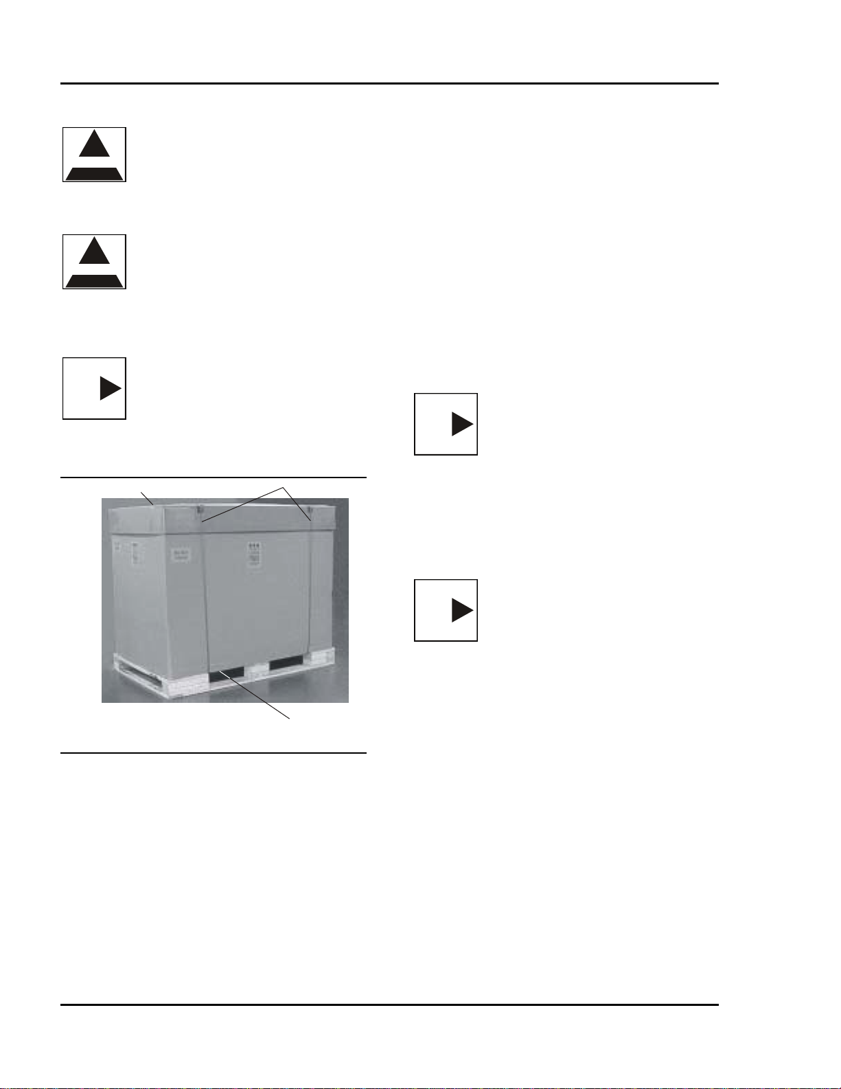
1. Cut the strapping around the shipping box, and
remove the top cover (FIGURE 1-1).
Straps
Top Cover
MANUAL FOOT
PUMP
Carton 9. Press the LOCK Button on the primary hand
pendant to extend the locking cylinders. The
LOCK LED on the primary hand pendant will
illuminate.
FIGURE 1-1 SHIPPING CONTAINER
2. Remove the ramp from the box.
3. Cut and remove all strapping and top bracing
frames. 10. Remove the lag screws that retain the bracing
supports. See FIGURE 1-2.
•Be careful not to mar finish.
•Remove the plastic bag covering the table.
Rev. 2 70-000-0026
1-2

OPERON B 810 SURGICAL TABLE INSTALLATION INSTRUCTIONS
FIGURE 1-2 SHIPPING CLAMPS
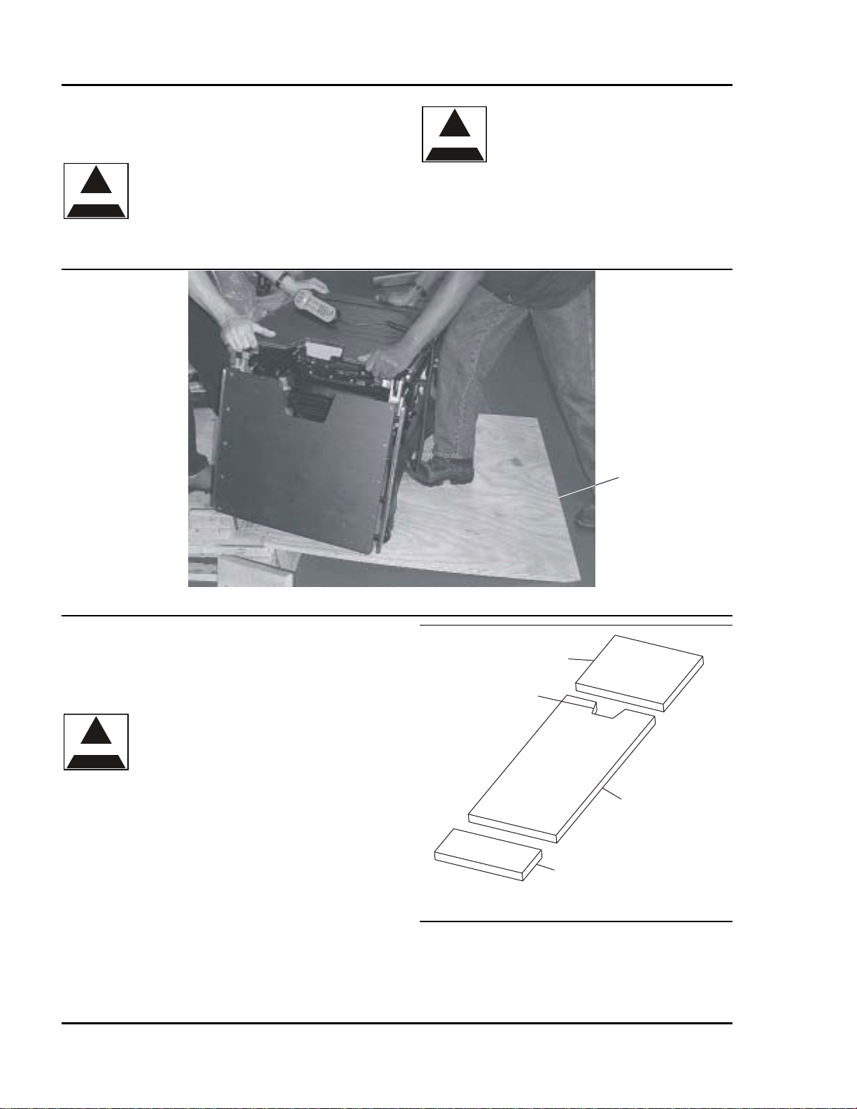
11. Align the ramp on the side of the shipping skid
(FIGURE 1-3). 12. Remove the slats beneath the base.
FIGURE 1-3 LOADING/UNLOADING RAMP
Remove screws that secure bracing
Ramp
Shipping Skid
6-1-0220-26_1
70-000-0026 Rev. 2
1-3
OPERON B 810 SURGICAL TABLE
INSTALLATION INSTRUCTIONS
13. Press the UNLOCK button on the pendant. This
will raise the feet and allow the casters to rest on
the pallet.
CAUTION
CAUTION — Do not attempt to
lift the table by its seat section or
side rails. Do not allow the table
to drop off the ramp, as this can
damage the casters.
WARNING
WARNING — POSSIBILITY OF
TIPPING: The table will roll
freely with the legs unlocked. At
least two people are required to
roll the table down the ramp.
14. With a partner, slowly move the table down the
ramp (FIGURE 1-4).
15. Save all packaging materials.
FIGURE 1-4 REMOVE TABLE FROM SKID
INSTALLATION
Installing the Pads
The tabletop is fitted with a matching set of
conductive radiolucent pads.
CAUTION
CAUTION — The anti-static
properties of the table depend on
the use of the recommended
mattress. Compromise of the anti-
static properties could expose the
patient or OR personnel to an
electrostatic shock. It could also
deliver a shock to the table’s
electronics that could damage or
destroy critical components.
FIGURE 1-5 PAD SET
To install the pads, align them with the edge of the
tabletop and press down. Velcro tape will hold the
pads in place.
Ramp
6-1-0220-27_1
Leg Section
Perineal Cutout
Back/Seat
Headrest
Rev. 2 70-000-0026
1-4
OPERON B 810 SURGICAL TABLE INSTALLATION INSTRUCTIONS
To remove the pads, pull up at one corner and peel
them from the tabletop.
If pad replacement is necessary, replace with
Berchtold replacement pads.
Cleaning instructions are outlined under
“ ”” beginning on page 4-1.MAINTENANCE
Installing the Headrest
The headrest can be installed at either end of the table.
Attach headrest to back/seat section for standard table
set-up.
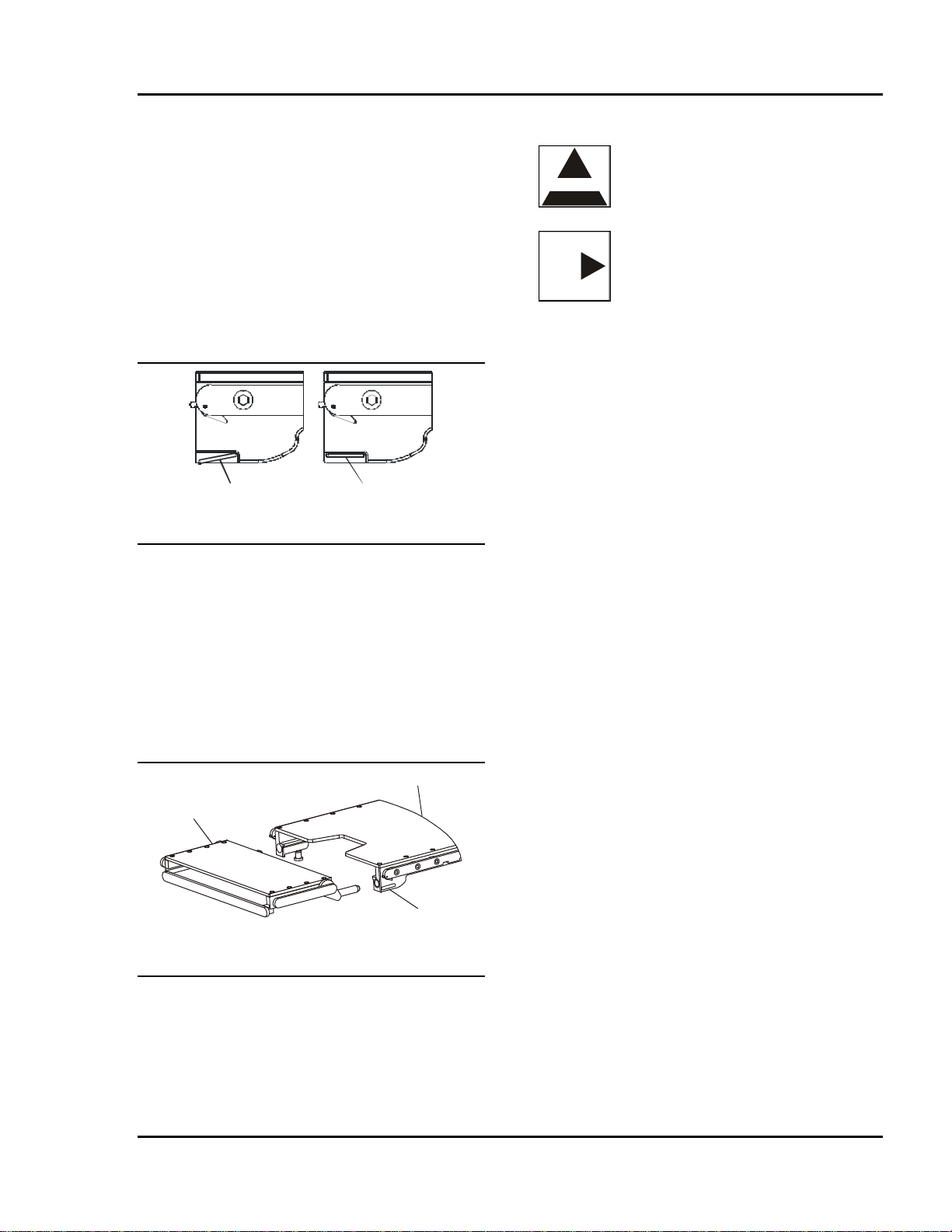
FIGURE 1-6 LOCKING LEVERS
Locking levers are located on the underside at the end
of the back and leg sections, and are used to secure the
headrest. The levers have two positions, locked and
unlocked.
Installing the Headrest:
1. Slide the headrest into its location as far as
possible, until you hear the locks engage.
2. Pull the headrest towards you to ensure that it is
locked into place.
FIGURE 1-7 HEADREST
Removing the Headrest:
1. Depress the two locking levers on the underside
of the table while you pull the headrest away from
the table.
2. Grasp the headrest on each side, and remove.
CHECKS AND ADJUSTMENT
WARNING
WARNING — The installation checkout
is necessary to ensure that handling
during shipment did not damage the
table.
NOTE
NOTE — If the table was stored where
the ambient temperatures were
significantly hotter or colder than 50° to
100° Fahrenheit (10° to 38° Celsius),
the table’s hydraulic fluid may have
expanded or contracted enough to affect
the positions of table sections. This
situation will correct itself as the table
warms or cools to room temperature.
After carefully uncrating the table, perform the
following checks:
1. Be sure that all accessories and attachments have
been removed from packing material.
Locked
Position Unlocked
Position 2. Examine table to be sure that all straps, shims,
and other packaging materials have been
removed.
3. Verify that the AC line voltage (mains) is within
the range of 108 to 132VAC.
4. Operate the table to confirm the articulation range
of all functions. Follow the checklist below:
•Table locking system engages and disengages
properly and immobilizes table.
•Tabletop travels from a minimum height of
28'' (711 mm) to a maximum of 48” (1219
mm) (without pads).
•Slide forward and reverse moves tabletop
through 12'' (305 mm) of travel.
•Tabletop tilts right and left 20°.
•Leg section adjusts from 0° above horizontal
to a minimum of 105° below horizontal.
•Back section adjusts from 80° above
horizontal to 40° below horizontal.
•Kidney elevator raises 3'' (76 mm) above
table surface and retracts properly.
•Trendelenburg and reverse Trendelenburg
allows movement to 30° above and below
horizontal.
•Flex position enables formation of an
inverted “V” of 225°.
Back Section
Locking
Lever
Headrest
70-000-0026 Rev. 2
1-5
OPERON B 810 SURGICAL TABLE
INSTALLATION INSTRUCTIONS
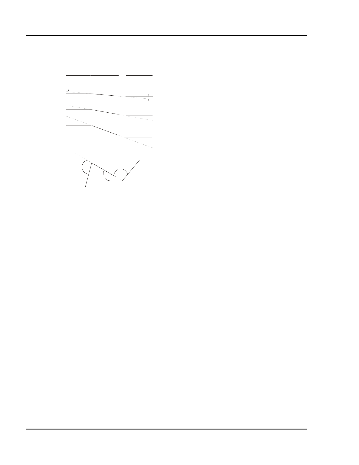
•Chair position enables formation of a chair
(see FIGURE 1-8).
leg seat bac
k
Initial
State
1st
Movements
Maximum
Articulation
105°
30°
80°
5°5°
6-1-0220-21_1
10°
10
°
20°
20°
FIGURE 1-8 CHAIR POSITION
•Return-to-Level returns all table sections to
within 1 degree of level head-to-foot and
side-to-side.
•Auxiliary control pendant and manual foot
pump operate correctly. (Refer to MANUAL
on page 2-7.)
FOOT PUMP
5. Inspect exterior surfaces for presence of hydraulic
fluid, especially under the base and side panels. If
a leak is evident, contact the manufacturer.
6. It is recommended the batteries be fully
charged overnight before introducing table
into service. The charging system is activated
when the table is plugged into mains AC power
(hospital receptacle) and the green charging
indicator lamp next to the plug is illuminated.
SETTING THE TABLE LEVELS
The table must know the zero position of all
articulation functions for the return-to-level function
to work properly. These zero positions are set at the
factory, but they should be checked when the table is
first installed and adjusted if necessary. The level
settings also should be checked periodically and reset
whenever necessary.
There are two ways to set the zero (or level) position
for each articulation. One uses the service software
program and is explained in detail in the Service and
Parts Manual (70-000-0027). The other is explained
below:
1. Level all sections using the hand pendant for
motion control and an accurate level for
measurement:
•Headrest
•Back
•Kidney
•Seat
•Leg
•Tilt
•Trendelenburg
2. Turn the main ON/OFF switch in the base power
center to the OFF position.
3. Perform the following actions as listed:
a. Press and hold the OFF button on the hand
pendant.
b. Press and hold the LEVEL button on the
hand pendant.
c. While continuing to hold both the hand
pendant OFF and LEVEL buttons, turn the
main ON/OFF switch in the base power
center to the ON position.
The table will record the leveled positions as the zero
positions and will return to these settings whenever the
Return-to-Level button in pushed.
AC FUSES (MAINS AC)
The table has been supplied with two 8-amp 5x20mm
time delay fuses in the power cord receptacle. These
fuses are accessible through the right hand power
center without removing the covers. (See FIGURE 2-
2 for the power center location.)
Rev. 2 70-000-0026
1-6
OPERON B 810 SURGICAL TABLE
GENERAL INFORMATION
GENERAL INFORMATION
GENERAL DESCRIPTION
The Berchtold OPERON B 810 surgical table is a
remote controlled, full-function design offering a
high level of patient positioning and imaging
flexibility to the surgical team. The table can be
activated by AC power through the power cord (input
range of 115V ±10%) or by battery power, which
requires no power cord except when charging the
batteries.
An electric motor with a screw drive is used to slide
the table top head to foot.
Hydraulic cylinders are used to articulate the table's
sections. Hydraulic pressure is provided by a motor
driven pump during normal use, and by a manual foot
pump in manual back-up mode.
A hand-held control pendant is used to control table
positions.
The tabletop is divided into the following sections
(FIGURE 2-1):
•Headrest
•Back Section
•Kidney Elevator
•Seat Section
•Leg Section
A leg extension can be added to extend the tabletop
surface.
RADIOLUCENT TABLE TOP AND PADS
The tabletop surface is made from electrically
conductive radiolucent panels. The table is fitted
with a matching set of conductive radiolucent pads.
Velcro tape holds the pads in place.
CAUTION
CAUTION — Protect the top and
bottom surfaces from nicks and
scratches. Scratches more than 0.005
inches (127 microns) deep may appear
on x-rays. Damaged or scratched
panels should be replaced if x-ray
quality is affected.
Each table section has a cassette channel that can
accommodate x-ray cassettes up to 14'' x 17'' (356 x
432 mm).
INTERCHANGEABLE HEADREST
The tabletop has perineal cutouts in both seat and
back sections. The back/seat pad can be reversed to
expose the desired cutout. The headrest can be
interchanged to allow for normal and reversed patient
orientation.
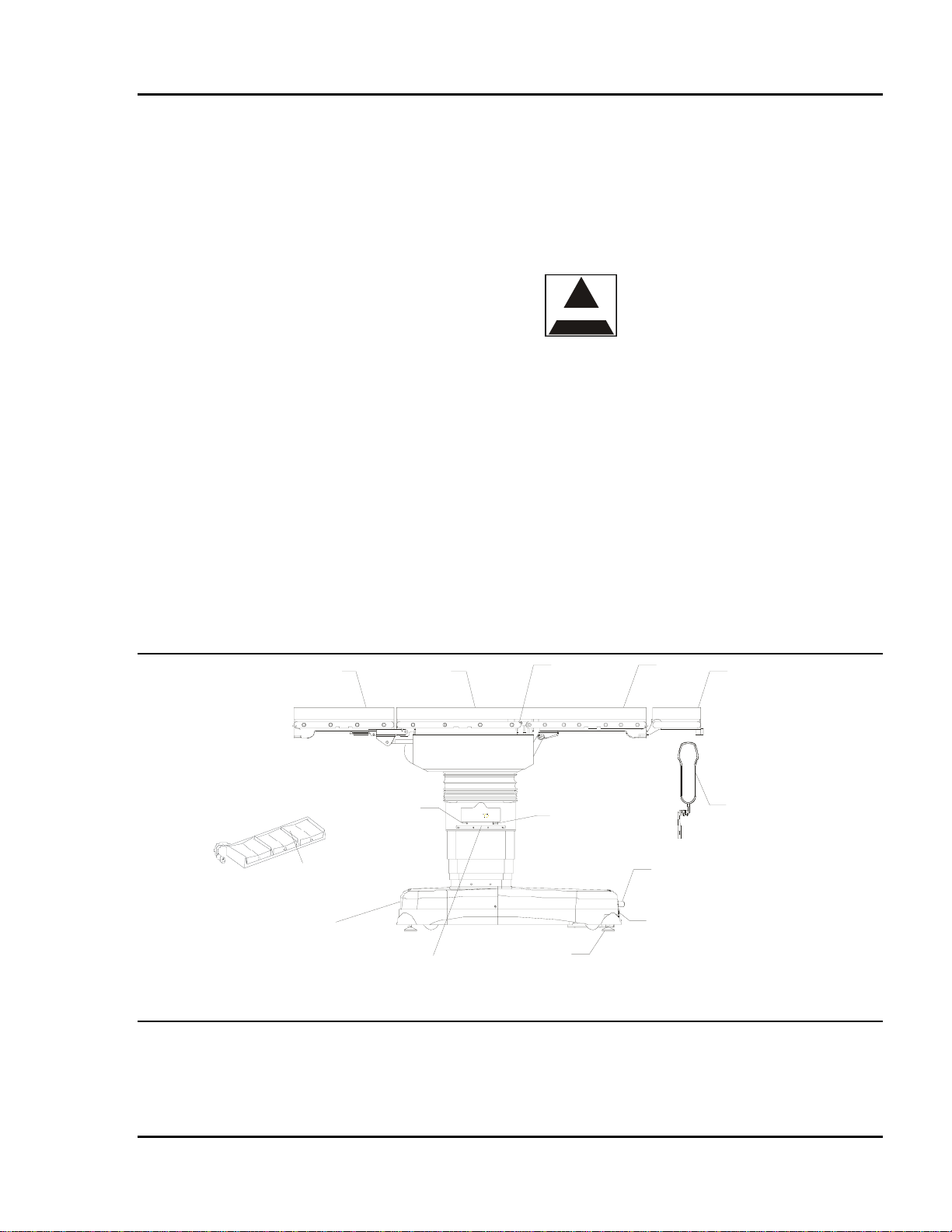
Detachable
Leg Section Seat
Section Kidney
Elevator Back
Section Headrest
Primary
Hand
Pendant
Primary Hand
Pendant
Receptacle
Footswitch
Receptacle
Manual Foot Pump
Footswitch
Located on this end of
Base:
Power Entry Module,
Fuses, and Auxiliary
Hand Pendant Drawer
Warning
Label Floor Feet
RS232 Port
FIGURE 2-1 OPERON B 810 SURGICAL TABLE
70-000-0026 Rev. 2
2-1
OPERON B 810 SURGICAL TABLE
GENERAL INFORMATION
POWER SUPPLY
WARNING
WARNING — Repeated breaker
tripping or fuse replacement may
indicate a ground fault or overload
condition. The table will not operate
reliably under these conditions, and
may be electrically unsafe. Do not use
the table until these conditions are
corrected.
NOTE
NOTE — Recharge the batteries as
indicated by the battery indicator on
the control pendant. For longevity, it is
good practice to charge the batteries at
least once a week.
When the table is plugged into a 120VAC receptacle,
it is powered by AC (mains). When the power cord is
not plugged in, the batteries provide power to the
table. In either case, the ON/OFF switch on the base
must be ON to articulate any table sections. When the
ON/OFF switch on the base is OFF, the table's
electronics and pump motor are isolated from the
power supply and the batteries, regardless of the
pendant used.
When the charge indicator lamp near the power cord
receptacle is lit, the table senses AC power and
activates the battery charging system. If AC is
present, the battery charging system is activated
whether the ON/OFF switch on the base is in the ON
or OFF position. The table can remain plugged into
AC indefinitely without damaging the batteries.
The battery indicator on the primary hand pendant
displays the battery charge status. This display has
three sections: green (full charge), yellow (low
charge), and red (recharge). Only one color will be
activated at a time.
NOTE
NOTE — In the unlikely event of a
control failure, the table movements
can be stopped by switching the
breaker on the base to the off (down)
position.
FUSES
Two sets of fuses are accessible without removing the
base covers. The first set, located within the
receptacle for the power cord, contains two fuses.
These fuses protect against current surges in the AC
(mains) line. The second set, located behind the
hinged door next to the ON/OFF switch, contains four
fuses. Three of these fuses protect against surges in
the DC circuitry; one fuse serves as a spare. Fuses F3
and F4 are 20 Amp rated. Fuse F5 is 2 Amp rated.
In addition to the fuses, the ON/OFF switch serves as
a circuit breaker with a 20 Amp rating.
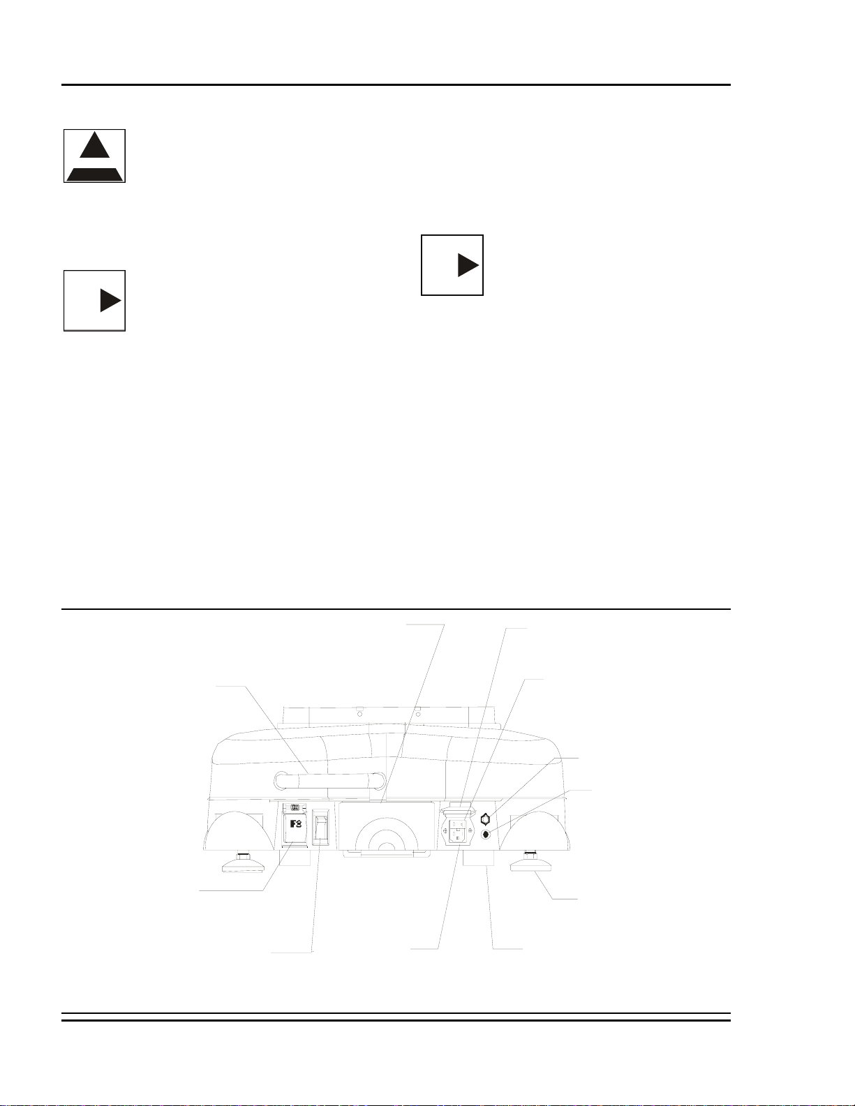
See FIGURE 2-2 for the fuse locations. See FIGURE
2-3 for the product identification and fuse information
label.
F4
Auxiliary Hand
Pendant Door Power Entry
Cover
Manual Foot
Pump Pedal Fuse Drawer,
AC Mains Fuses (F1 and F2)
2@5X20mm 8A Time Delay
Charging Indicator
Grounding Post
Fuse Cover
DC Battery,
Pump and
Pendant Fuses
3 ATO Fuses;
3@ 20A (P/N 304849) Floor Feet
ON/OFF Switch
(20Amp Circuit Breaker) Power Cord
Rece
p
tacle Caster
FIGURE 2-2 BASE COMPONENTS POWER SUPPLY
Rev. 2 70-000-0026
2-2
Other manuals for OPERON B 810
1
Table of contents
Other Berchtold Medical Equipment manuals


Popular Medical Equipment manuals by other brands

Bovie
Bovie Aaron 1250 user guide

Olympus
Olympus TJF 160VR Instructions for safe use

Med-Mizer
Med-Mizer ActiveCare-Standard user manual

Stryker
Stryker Performance-PRO XT Operation & maintenance manual

Carlo De Giorgi
Carlo De Giorgi 640/00 User and maintenance manual

idi
idi Aspect 100RTL Q-CARD Operator's manual


Inogen
Inogen One G3 Technical manual

Joerns
Joerns Oxford User instruction manual

Coviden
Coviden Kangaroo user manual

VitalConnect
VitalConnect VistaPoint 3.0 QuickStart and Instructions for Use

Getinge
Getinge HS 6613 AR-2 manual

MD Orthopaedics
MD Orthopaedics Mitchell Ponseti Ankle Foot Orthosis Instructions for use