Beretta BREVA EX 9000-1 User guide

Installer manual
BREVA EX
EN

BREVA EX
2
Dear Technician,
We would like to congratulate you on having recommended a unit: a modern product that is capable of ensuring maximum comfort at length,
with a high degree of reliability, efficiency, quality and safety.
While your technical skills and knowledge will certainly be more than sufficient, this booklet contains all the information that we have deemed necessary
for the device's correct and easy installation.
Thank you again, and keep up the good work.
BERETTA S.p.A.
COMPLIANCE
BREVA EX heat pumps are compliant with the following European Directives:
-Low Voltage Directive 2014/35/EU
-Electromagnetic Compatibility Directive 2014/30/EU
-RoHS Directive 2011/65/EU
-ErP Directive 2009/125/EC and Regulation 2012/206/EC
-WEEE Directive 2012/19/EU
-F-Gas Regulation 2014/517/EU
RANGE
Model Code
BREVA EX 9000-1 20171581
BREVA EX 12000-1 20171583
BREVA EX 18000-1 20171585
BREVA EX 24000-1 20177622
ACCESSORIES
For the complete list of accessories and the information relating to their usage combinations, please refer to web www.berettaclima.it.

BREVA EX
3
TABLE OF CONTENTS
1 GENERAL INFORMATION..................................
1.1 General Notices...............................................................
1.2 Safety precautions...........................................................
1.3 Unit description................................................................
1.4 Safety and adjustment devices........................................
1.5 Identification.....................................................................
1.6 Layout..............................................................................
1.7 Technical specifications...................................................
1.8 Operating limits................................................................
1.9 Cooling circuit..................................................................
2 INSTALLATION....................................................
2.1 Receiving the product......................................................
2.2 Labels positioning............................................................
2.3 Dimensions and weight...................................................
2.4 Storage............................................................................
2.5 Handling and removal of the packing..............................
2.6 Place of installation..........................................................
2.7 Recommended distances................................................
2.8 Positioning.......................................................................
2.9 Installation on old systems or systems in need of............
upgrading.......................................................................
2.10 Refrigerating connection..................................................
2.11 Wiring diagram.................................................................
2.12 Electrical connection........................................................
3 COMMISSIONING AND MAINTENANCE..........
3.1 Preparation for first commissioning..................................
3.2 Putting into service..........................................................
3.3 Ordinary maintenance......................................................
3.4 Segnalazione di funzionamento e allarmi.........................
4 DISPOSAL............................................................
The following symbols are used on the product:
The R32 refrigerant gas is slightly inflammable and odourless.
Avoid proximity to sources of ignition in con- tinuous
operation (open flames, gas household appliances, electric
stoves, lit cigarettes, etc).
For more information, see the installation and technical service
instructions.
Before performing maintenance and service tasks, read the
installation and technical service instructions.
Before the installation, read the installation and technical
service instructions.
The following symbols are used in this publication:
WARNING = actions requiring special care and appropriate
training.
DO NOT = actions that MUST ON NO ACCOUNT be carried
out. This booklet cod. Doc-0097018 rev.0 (03/2020) consists of pages.
4
4
4
5
5
5
6
8
10
10
11
11
11
11
12
12
12
12
13
13
14
19
20
23
23
23
24
24
27
28

1 | GENERAL INFORMATION
4
1 GENERAL INFORMATION
1.1 General Notices
When you get the product, check immediately that the contents are
all present and undamaged. Contact the dealer if you notice
any problems.
The product' s installation must be carried out by an authorised
company that will issue a declaration of the installation's conformity
to the product's owner once the work has been completed,
indicating that the work has been carried out in accordance with the
standards of good practice, current National and Local regulations,
and the indications provided by in the instruction booklet
accompanying the device.
The product must be used for its intended purpose, as stated by
for which it has been expressly manufactured. shall
bear no responsibility, whether of a contractual or non-contractual
nature, for any damage caused to people, animals, or property due
to incorrect installation, adjustments, or maintenance, or improper
use.
Suitable clothing, instrumentation, and accident-prevention devices
must be utilized during the installation and/or maintenance
operations. shall bear no responsibility for any failure to
comply with current safety and accident-prevention regulations.
During installation and/or service operations, keep the area around
the unit tidy and clean.
Comply with the legislation in force on the country of deployment
with regard to the use and disposal of packaging, of cleaning and
maintenance products and for the management of the unit's
decommissioning.
Any repair and maintenance interventions must be carried out by
Technical Support Service, in accordance with the
provisions contained in this publication. Do not modify or tamper
with the unit as dangerous situations may arise and the unit
manufacturer will not be liable for any damage caused.
In the event of any functional anomalies or fluid leaks, set the
system's main switch to its "off" position. Promptly contact your
local Technical Support Service, and do not perform any
interventions upon the device on your own.
The units contain refrigerant gas: operate carefully so as to avoid
damaging the gas circuit and the fin bank.
Do not place any inflammable object (spray cans) within a 1 metre
radius from the air expulsion.
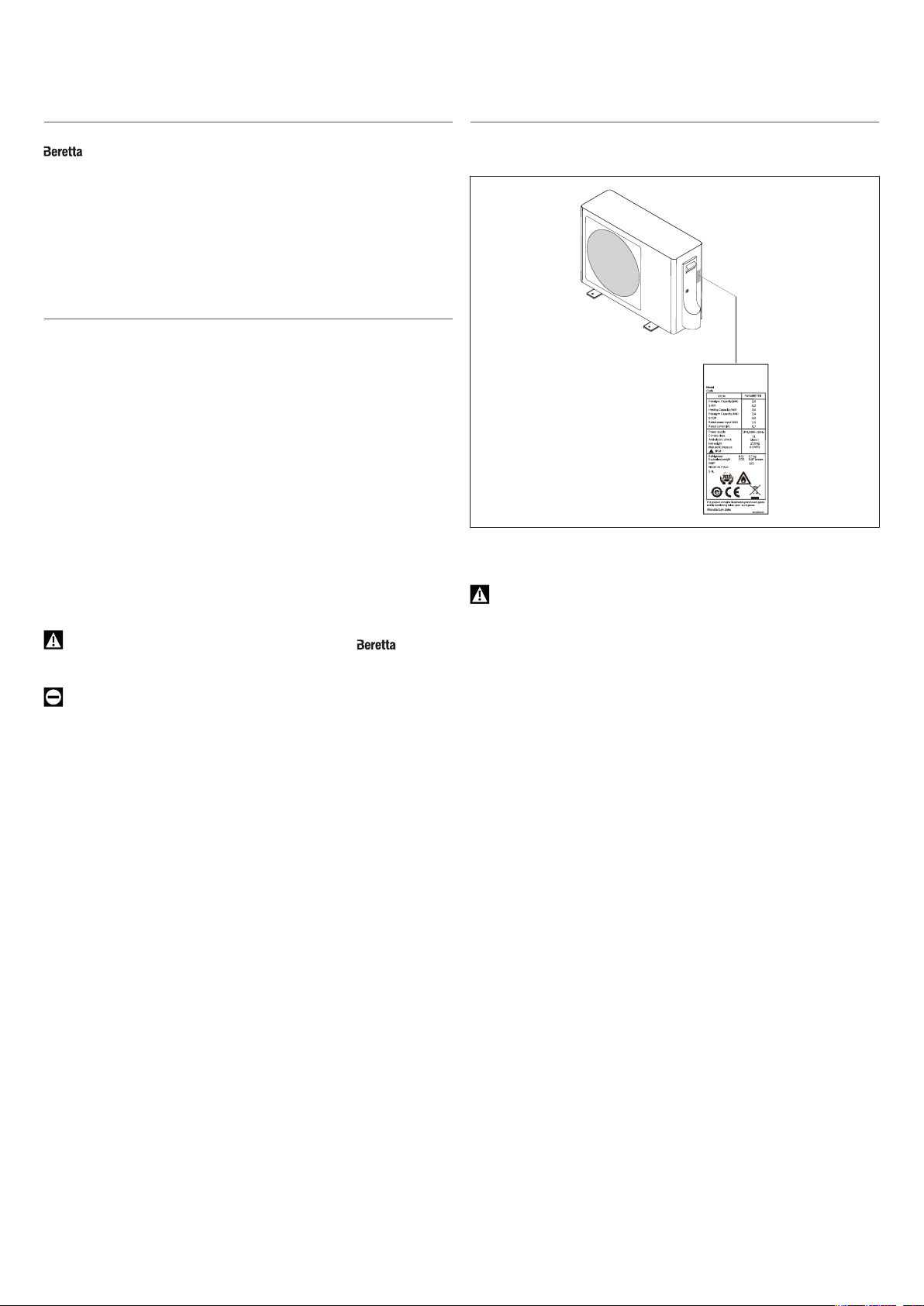
According to EU Regulation no. 517/2014 regarding certain
fluorinated greenhouse gases, the total amount of refrigerant
contained within the installed system must be indicated. This
information can be found on the unit technical data plate.
This unit contains fluorinated greenhouse gases covered by the
Kyoto protocol. Maintenance and disposal activities must be carried
out exclusively by skilled personnel.
The R32 refrigerant gas is slightly inflammable and odourless.
Carefully read the safety data sheet available from the dealer.
This booklet is an integral part of the device, and must therefore be
carefully preserved, and must ALWAYS accompany it, even in the
event that it is sold to another Owner or User, or is transferred to
another system. If it is damaged or lost, another copy can be
requested to Technical Support Service in your Area.
1.2 Safety precautions
It should be noted that the use of products that utilize electric energy
requires certain essential safety regulations to be respected, including the
following:
Do not allow children or unassisted disabled people to use the unit.
Do not touch the unit while barefoot and/or partially wet.
Do not spray or throw water directly on the unit.
It is forbidden to place weights on the device.
It is strictly forbidden to touch the coil fins, the moving parts, to place
any body parts between them, or to insert pointy objects into the
grilles.
It is forbidden to perform any technical interventions or cleaning
operations before having disconnected the device from its electrical
power supply, by setting the system's main switch to its "OFF"
position.
It is forbidden to modify the safety or regulation devices without the
authorisation of the manufacturer.
Do not pull, detach or twist the electrical wires coming out of the
unit, even when the unit is disconnected from the power grid.
The packing material must not be disposed of in the surrounding
environment and must be kept out of children reach, as it can be
dangerous. It must be disposed of according to the regulations in
force.

1 | GENERAL INFORMATION
5
1.3 Unit description
BREVA EX is a heat pump outdoor unit that can be coupled to
indoor units of the same series for the air-conditioning of
small/middle-sized rooms. Designed for outdoor installation, it is suitable
for use in residential and small business premises.
The rotary-type compressor is controlled via DC-Inverter control with
continuous modulation from 20% to 110%, thus ensuring high energy
standards. The fan DC motor improves performance and sound comfort.
The expansion valve electronically optimises the flow of refrigerant within
the circuit (24000-1 only).
1.4 Safety and adjustment devices
The device safety and setting are achieved thanks to
-compressor motor thermal protection, which is triggered in case
the current consumed by the compressor is excessive
-gas delivery temperature sensor, which transmits the detected
value to the electronic board that is triggered in case of
overtemperature (110°C)
-anti-freeze sensor, which transmits the temperature value as
detected by the heat exchanger to the electronic board that is
triggered when the heat exchanger is clogged by frost formations
-outdoor air temperature sensor, which transmits the detected
value to the electronic board that is triggered in order to adjust
the operation of the unit indoor components to the variation of
weather conditions
Models 12000-1, 18000-1, 24000-1 only
-suction temperature sensor, which transmits the detected value
to the electronic board that is triggered in order to adjust the flow
of refrigerant gas or to stop the unit in case of overtemperature
(40°C)
Safety device replacement must be carried out by Technical
Support Service, using only original components. Please refer to the
spare parts catalogue.
IT IS FORBIDDEN to operate the device with faulty safety systems.
1.5 Identification
The unit can be identified through the technical data plate:
Technical data plate
Contains the device's technical and performance data.
The tampering, removal, or absence of the identification plates will
not allow the product to be properly identified by its serial number.

1 | GENERAL INFORMATION
6
1.6 Layout
MODEL 9000-1
1Upper panel 6Rotary compressor 13 Capillary tube
2Fan protection grille 8Intake separator 14 Cycle reversal valve
3Connections cover 9Gas line connection 15 Terminal board for electric connections
4Handle for handling 10 Liquid line connection 16 Electric panel cover
5Heat exchanger 11 Muffler
6Electric fan 12 Filter
MODEL 12000-1
1Upper panel 6Electric fan 13 Filter
2Fan protection grille 8Rotary compressor 14 Capillary tube
3Support bracket 9Intake separator 15 Cycle reversal valve
4Connections cover 10 Gas line connection 16 Terminal board for electric connections
5Handle for handling 11 Liquid line connection 17 Electric panel cover
6Heat exchanger 12 Muffler

1 | GENERAL INFORMATION
7
MODEL 18000-1
1Upper panel 6Electric fan 13 Filter
2Fan protection grille 8Rotary compressor 14 Capillary tube
3Support bracket 9Intake separator 15 Cycle reversal valve
4Connections cover 10 Gas line connection 16 Terminal board for electric connections
5Handle for handling 11 Liquid line connection 17 Electric panel cover
6Heat exchanger 12 Muffler
MODEL 24000-1
1Upper panel 6Electric fan 11 Filter
2Fan protection grille 6Intake separator 12 Electronic expansion valve
3Connections cover 8Rotary compressor 13 Cycle reversal valve
4Handle for handling 9Liquid line connection 14 Electric panel cover
5Heat exchanger 10 Gas line connection

1 | GENERAL INFORMATION
8
1.7 Technical specifications
Performance combined with BREVA IN
Model 9000-1 12000-1 18000-1 24000-1
Indoor unit 1 x 9000 1 x 12000 1 x 18000 1 x 24000
Cooling performance (1)
Capacity at rated air flow kW 2,60 3,60 5,00 7,00
Absorbed power at rated air flow kW 0,80 1,11 1,46 2,16
EER kW/kW 3,23 3,23 3,41 3,23
Capacity at maximum air flow kW 3,40 4,00 5,80 8,50
Absorbed power at maximum air flow kW 1,40 1,50 2 2,90
Capacity at minimum air flow kW 0,80 1 1,30 2,20
Absorbed power at minimum air flow kW 0,30 0,30 0,40 0,70
Cooling energy data (2)
SEER kW/kW 6,20 6,40 6,10 7,10
Energy class A++ A++ A++ A++
Annual energy cons. kWh/annum 147 197 287 350
Heating performance (3)
Capacity at rated air flow kW 2,90 3,70 5,20 8,10
Absorbed power at rated air flow kW 0,78 0,99 1,40 2,18
COP kW/kW 3,71 3,71 3,71 3,71
Capacity at maximum air flow kW 3,80 4,60 6,00 10,00
Absorbed power at maximum air flow kW 1,40 1,50 2,50 2,90
Capacity at minimum air flow kW 1 1,10 1,40 2,40
Absorbed power at minimum air flow kW 0,30 0,40 0,52 0,70
Energy data for Average climatic profile (4)
Pdesign at -10 °C kW 2,40 3,20 4,60 5,60
SCOP kW/kW 4,10 4,10 4 4
Energy class A+ A+ A+ A+
Annual energy cons. kWh/annum 819 1092 1610 1963
Energy data for Warm climatic profile (4)
Pdesign at +2 °C kW 2,00 2,80 4,60 5,60
SCOP kW/kW 5,10 5,10 5,10 5,10
Energy class A+++ A+++ A+++ A+++
Annual energy cons. kWh/annum 549 769 1263 1537
(1) Outdoor air: 35 °C D.B., Indoor air: 27 °C D.B. / 19 ° W.B.
(2) In compliance with 626/2011 regulation
(3) Outdoor air: 7 °C D.B. / 6 °C W.B., Indoor air: 20 °C D.B.
(4) In compliance with EU 206/2012 regulation

1 | GENERAL INFORMATION
9
Outdoor unit data
Model 9000-1 12000-1 18000-1 24000-1
Nominal capacity kW 2,60 3,60 5 7
Nominal power input kW 0,80 1,11 1,46 2,16
Rated frequency Hz 51 75 70 68
Maximum frequency Hz 70 70 85 90
Minimum frequency Hz 24 29 20 20
Nominal current consumption A 3,60 4,90 6,50 9,60
Max. current input A 6,20 6,70 8,90 13
Minimum current consumption A 1,40 1,40 1,80 3,20
Nominal capacity kW 2,90 3,70 5,20 8,10
Nominal power input kW 0,78 0,99 1,40 2,18
Rated frequency Hz 66 64 73 79
Maximum frequency Hz 99 99 119 91
Minimum frequency Hz 24 25 20 15
Nominal current consumption A 3,50 4,40 6,30 9,70
Max. current input A 6,20 6,70 11,30 13
Minimum current consumption A 1,40 1,80 2,30 3,20
Electrical characteristics
Power supply V/Ph/Hz 230/1/50 230/1/50 230/1/50 230/1/50
Compressor
Compressor Tipo Rotary Rotary Rotativo
Doppio Rotativo
Doppio
Oil Tipo FW50S ACS-68R RM-LP56EG ACS-68R
Oil charge l 0,32 0,32 0,48 0,50
Refrigerant Tipo R32 R32 R32 R32
Refrigerant charge kg 0,50 0,62 0,90 1,20
Fan
Fan Tipo Assiale - DC Assiale - DC Assiale - DC Assiale - DC
Quantity n. 1 1 1 1
Maximum air flow m³/h 1900 2000 2500 2900
Minimum speed Rpm 300 300 300 300
Maximum speed Rpm 800 900 950 800
Maximum power input kW 0,04 0,04 0,04 0,05
Cooling sound levels
Sound power level dB(A) 62 63 65 65
Sound pressure level dB(A) 47 48 53 52
Heating sound levels
Sound power level dB(A) 62 63 65 65
Sound pressure level dB(A) 47 48 53 52
(1) Outdoor air: 35 °C D.B., Indoor air: 27 °C D.B. / 19 ° W.B.
(2) Outdoor air: 7 °C D.B. / 6 °C W.B., Indoor air: 20 °C D.B.

1 | GENERAL INFORMATION
10
1.8 Operating limits
Operating mode Temperature Min Max
Cooling Indoor air (W.B.) °C 21 35
Outdoor air (D.B.) °C -20 43
Heating Indoor air (D.B.) °C 10 27
Outdoor air (W.B.) °C -20 24
The values are based on the following condition:
-pipe length: 5 m
-difference in height: 0 m
-air flow: maximum
1.9 Cooling circuit
The cooling circuit is of the heat pump type with a refrigerant gas reversal cycle. The source fluid utilised is the outdoor air, while the utility-side fluid is
the air inside the rooms.
During the wintertime, the heat pump extracts the thermal energy from the outdoor air and delivers it to the room air, thereby heating it. During the
summertime the cycle is reversed, and the thermal energy is extracted from the room air, which is cooled, and is delivered to the outdoor air.
AOutdoor unit 5Heat exchanger 11 Connection pipes
BIndoor unit 6External air probe 12 Three-way shut-off valve
1Compressor 7Defrost temperature sensor 13 Intake separator
2Discharge temperature sensor 8Capillary tube 14 Intake sensor (excluding 9000-1)
3Cycle reversal valve 9Electronic expansion valve
(24000-1 only)
4Electric fan 10 Two-way shut-off valve

2 | INSTALLATION
11
2 INSTALLATION
Ensure that the installation and operation sites are properly ventilated
in order to disperse any gas leaks that could cause flames during
activities with intense heat generation and high temperature.
Avoid proximity to sources of ignition in continuous operation (open
flames, gas household appliances, electric stoves, lit cigarettes, etc).
Use equipment suitable for the system refrigerant.
Use an electronic leak finder properly calibrated for the system
refrigerant.
It is forbidden to use leak finders with halogen lamps.
2.1 Receiving the product
BREVA EX is supplied in a single pack, protected by a cardboard
box and by polystyrene elements.
The following material is placed inside the packaging, below the unit
Document envelope:
-Instruction's book for the installer and for the Technical Service in
Italian
-Instruction's book for the installer and for the Technical Service in
English
-Warranty/Spare parts labels.
-energy label
-etichetta gas refrigerante
-contact sheet
It is also supplied as kit:
-Condensate discharge connector
-4 x vibration dampers
-screws to connect refrigerant connections cover
When you get the product, check immediately that the contents are
all present and undamaged. Contact the dealer if you notice
any problems.
The Instruction book comes with the equipment and it should be
taken, read and kept carefully.
The document envelope must be kept in a safe place. Any duplicate
must be requested from BERETTA which reserves to charge the
cost.
2.2 Labels positioning
APackage label
BTransport label
2.3 Dimensions and weight
Model 9000-1 12000-1 18000-1 24000-1
Packaging dimensions
H mm 620 625 625 780
L mm 920 954 954 1046
P mm 351 409 409 460
Weight kg 30 30,30 36,50 52,30
Model 9000-1 12000-1 18000-1 24000-1
Product dimensions
H mm 540 550 550 697
L mm 780 800 800 890
L1 mm 856 860 860 986
P mm 245 280 280 353
Weight kg 27 27 32,70 47,30

2 | INSTALLATION
12
2.4 Storage
If the product is stored in a room before installation check:
-there aren't continously operating ignition sources (open flames,
gas appliances, electric heaters,..) within a radius of 2.5 m.
-there is adequate ventilation
The product must be stored of according to the regulations in force.
2.5 Handling and removal of the packing
Before unpacking, personal protective clothing should be worn and
used transport means and tools suitable for the size and weight of
the unit.
Check refrigerant leak inside the packaging with a leak detector
suitable for the refrigerant used in the system.If a gas leak is
detected, probably the refrigerant circuit is damaged and the
product can't be installed; finally call Technical Service .
Product handling can also be done manually by grasping the handles
provided on the packaging.
1Handles
2Strapping bands
3Document envelope and material supplied as kit
Follow the below instructions for packing removal and product handling:
-transport the equipment in the installation place
-cut strapping bands
-lift and remove the cardboard pack
The unit is supplied with the connections cover fixed to the unit with
adhesive tape to avoid damage during transport and handling
operations.
Before handling operations it is necessary to fix the connections cover to
the unit:
1Adhesive tape
2Connections cover
3Fixing screw
4Handles
-remove the adhesive tape
-unscrew the connections cover fixing screw from the unit
-position the connections cover
-Reassemble the fixing screws.
-handle the unit by grasping the handles provided.
-remove the document envelope
In manual operation it is compulsory to respect always the maximum
weight per person provided for by the national laws and standards.
Handle with care
The equipment must always be handled vertically
Do not tilt the equipment over 15°
The unit’s weight is concentrated on the compressors side
(connection covering side).
The packing material must not be disposed of in the surrounding
environment and must be kept out of children reach, as it can be
dangerous. It must be disposed of according to the regulations in
force.
2.6 Place of installation
The location of BREVA EX devices must be determined by the
system's designer or by another competent person, and must take into
account the technical requirements, as well as any current local
regulations that require specific permits to be obtained. (e.g.: zoning,
architectural, environmental protection, etc.).
It is therefore recommended to obtain all the necessary permits before
installing the device.
is designed for outdoor installation.
Avoid:
-positioning the unit in air shafts and/or basement window wells
-any obstacles or barriers that will cause the expelled air to
recirculate
-locations with aggressive or explosive atmospheres or with
inflammable fluids
-confined locations in which the device's sound levels might be
compounded by reverberations or resonances
-proximity to bedrooms and rooms for resting
-positioning in corners where dust, leaves, or any other materials
typically accumulate, which could compromise the device
efficiency by obstructing the airflow
-situations in which the air expelled from the device might enter the
habitation through doors or windows, thus creating an
inconvenience for the people inside
-situations in which the air expelled from the device will encounter
resistance from opposing winds
-direct exposure to sunlight and proximity to heat sources
Avoid placing the unit less than 1 metre away from radio and video
systems.
If the unit is installed in a windy location, fit an anti-wind grille to
protect the fan and check the correct functioning of the unit.
Decide where to place the unit considering the length of cooling lines
and the maximum difference of height allowed between the devices.
2.7 Recommended distances
The distances for the device installation and maintenance are shown in
the figure. The indicated spaces are necessary in order to prevent the
airflow from being blocked, as well as to allow normal cleaning and
maintenance operations to be carried out.

2 | INSTALLATION
13
2.8 Positioning
BREVA EX devices must:
-be positioned on a level surface that is capable of supporting their
weight
-be positioned on a sufficiently rigid surface that will not transmit
any vibrations to the underlying or adjacent rooms
Use the anti-vibration supports supplied with the device.
Model 9000-1 12000-1 18000-1 24000-1
A mm 140 130 130 130
B mm 500 510 510 628
C mm 140 160 160 130
D mm 256 313 313 356
They can be placed on the floor or suspended on supporting brackets.
Positioning on floor
1Fastening screw M4
2Anti-vibration element (supplied)
3Spirit level
-screw the unit to the ground
-tighten using a torque wrench
-apply a tightening torque of 3.5 Nm
Provide for lifting of the unit from the floor:
-20 mm without conveying of the condensate outlet
-90 - 100 mm to allow for the condensate discharge
If the device is installed in an area that is subject to heavy snowfalls,
place the unit in a raised position so as to prevent the air flow from
being blocked or install a roofing to protect it.
Adequate anti-freeze systems should be used for installations in
extremely cold areas, where there is a possibility of freezing.
While operating in heating mode, the unit generates condensate,
which will deposit on the support surface if there is not discharge.
This could freeze if the outdoor temperatures are below zero, thus
creating a hazard. In this case, appropriate barriers should be
installed in order to prevent people from approaching the unit.
1Lifting from the top
2Condensate discharge connector
Model 9000-1 12000-1 18000-1 24000-1
Connections
Condensate
drain
connection mm 16 16 16 16
Hanging position
Properly sized supporting brackets must be used if the device is
installed in suspension.
Ensure that the wall section does not include bearing elements,
pipes or electric lines.
1Supporting brackets
2Anti-vibration element (supplied)
3Fastening screw M4
2.9 Installation on old systems or systems in
need of upgrading
When BREVA EX is installed on old systems or systems in need
of upgrading, it is recommended to ensure that:

2 | INSTALLATION
14
-the electrical system is compliant with the applicable regulations
and has been installed by qualified professionals
In the event of a replacement, the system must be inspected by the
designer or by another competent person, and must be compliant
with the technical requirements, as well as the current legislations
and regulations.
The manufacturer shall bear no responsibility for any damages
caused by incorrect system installation.
2.10 Refrigerating connection
The dimensions and positions of cooling connections are shown
hereunder.
MODELLO 9000-1 - 24000-1
1Gas line connection
2Liquid line connection
3Service connection
MODELLO 12000-1 - 18000-1
1Gas line connection
2Liquid line connection
3Service connection
Model 9000-1 12000-1 18000-1 24000-1
Connections
Liquid line
connection Pollici 1/4 1/4 1/4 1/4
Gas line
connection Pollici 3/8 3/8 1/2 1/2
Charge
connection Pollici 1/2 1/2 1/2 1/2

2 | INSTALLATION
15
Model 9000-1 12000-1 18000-1 24000-1
Liquid line
connection mm 6,35 6,35 6,35 6,35
Gas line
connection mm 9,52 9,52 12,70 12,70
Charge
connection mm 12,70 12,70 12,70 12,70
To access the cooling connections:
-unscrew the fastening screw
-push down the connection covering panel
-remove the connection covering panel
The cooling pipes must respect the lengths and differences in height as
indicated in the following table.
Use pipes with the thickness indicated in the following table:
Model 9000-1 12000-1 18000-1 24000-1
Connection pipes
A m 10 10 15 15
B m 15 15 25 25
Maximum
length with
standard
charge
m 5 5 5 7
Additional
charge g/m 20 20 20 20
Pipe Ø Thickness
mm inches mm
6.35 1/4 0.8
9.52 3/8 0.8
12.7 1/2 0.8
15.88 5/8 1
Maximum operating pressure 4.3 Mpa.
In case of a drop in excess of 5 m, a siphon must be installed every
5-7 metres.
The given measures are the maximum permitted values.
Cooling connections featuring shut-off valves are preconfigured for
flare connections.
Cooling lines must be as straight as possible and any necessary
bends must have a radius grater than 40 mm.
Use clean hoses. Make sure the inside is free of dust, residues,
water.
Avoid the entry of uncondensable gases (air) in the circuit, otherwise,
with the unit in operation, high pressures with the risk of damages
might ensue.
Use copper pipes for cooling systems.
Use connecting pipes and tools appropriate for the system's
refrigerant.
It is forbidden to use second-hand cooling lines since their flare
connection seal is not guaranteed.
It is forbidden to use pre-charged cooling lines.
It is forbidden to carry out welding operations with refrigerant inside
the cooling circuit. If necessary, the refrigerant must be recovered
and the circuit must be cleaned with nitrogen without oxygen.
Connections
-position the connecting pipes
Before threading the lines through the hole in the wall, close the lines
ends.
-cut the pipe end square using a pipe cutter
-remove burrs keeping the cut edge facing down
-remove the flare nut on the unit connection
-insert it into the connection pipe
-flare the tube
Pipe Ø A
mm inches mm
6.35 1/4 9.1
9.52 3/8 13.2
12.7 1/2 16.6
15.88 5/8 19.7

2 | INSTALLATION
16
1Key
2Torque wrench
3Flare nut
Pipe Ø Tightening torque
mm inches Nm
6.35 1/4 18
9.52 3/8 42
12.7 1/2 55
15.88 5/8 60
Pipe Ø A
mm inches mm
6.35 1/4 17
9.52 3/8 22
12.7 1/2 26
15.88 5/8 29
-bring line ends with flare connection close to their coupling on the
unit
-manually rotate the flare nuts by 3 - 4 turns
-tighten the connections using a spanner and a counter spanner
Use a torque wrench to tighten so as to prevent damage to flare nuts
and gas leaks.
Use equipment suitable for the system refrigerant.
During the connection, keep the leak finder on and close to the unit
so that it signals any refrigerant leak.
Avoid using the refrigerant oil on the external part of the flaring.
Avoid proximity to sources of ignition in continuous operation (open
flames, gas household appliances, electric stoves, lit cigarettes, etc).
After connecting the cooling pipes:
-create a vacuum inside the pipes
-check for refrigerant leaks
-apply thermal insulating material on the joints
Pipe insulation
Connection pipes must be thermally insulated to prevent dispersions of
heat or formation of condensate.
1Gas pipe
2Condensation discharge
3Liquid pipe
4Heat insulation
5Adhesive tape
-insulate the liquid and gas pipes separately
-use insulating material that is thicker than 15 mm
-ensure that the insulating material adheres to the pipe without
gaps
-fix using adhesive tape
Do not tighten the adhesive tape too much, so as to avoid damaging
the insulation.
Avoid partial insulation of the pipes.
In case of use with outdoor temperature above 30 °C and relative
humidity above 80%, increase wall thickness up to 20 mm.
For gas pipes:
-ensure that the material used resists to temperatures up to 120°C
For liquid pipes:
-ensure that the material used resists to temperatures up to 70°C
Stop valves
Cooling connections feature shut-off valves.
During operations on the cooling circuit, start-up and service, it may be
required to open and close the valves.
AOpening
BClosing
1Service connection blanking plug
2On-off valve shaft
3Refrigerating pipe attachment
4On-off valve cover plug
5Hex wrench

2 | INSTALLATION
17
If required:
-remove the valve covering plug
-operate on the valve shaft with an hex wrench
-open or close according to what is needed
-immediately stop as soon as the valve shaft has reached the stop
point
-use a torque wrench calibrated on the valve diameter
Pipe Ø Hex
wrench
Valve
tightening
torque
Plug
tightening
torque
mm inches mm Nm Nm
6.35 1/4 5 6 25
9.52 3/8 5 6 25
12.7 1/2 5 8 30
15.88 5/8 5 10 35
Do not force beyond the stop point to prevent damaging the shaft
and causing leakage as a consequence.
At the end of the operations:
-refit the valve covering plug
Carefully check for absence of leakages from the closing point of the
plug.
Circuit tightness check
The appliance is tested at the factory and the indoor refrigerating circuit
tightness does not usually need to be checked.
The refrigerating circuit built on site needs to be checked instead.
To check tightness:
-keep the outdoor unit shut-off valves closed
AHigh pressure
BLow pressure
1Pressure regulator
2Nitrogen cylinder
3Pressure gauge unit
43-way valve service connection
13-way valve service connection
-charge the circuit with nitrogen through the service connection on
the 3-way shut-off valve
Do not use oxygen or acetylene or other flammable or poisonous
gases in the refrigerating circuit, as they can cause explosions.
-reach a pressure equal to 0.3 Mpa
-wait 3 minutes.
-check that the pressure has not dropped
-reach a pressure equal to 1.5 Mpa
-wait 3 minutes.
-check that the pressure has not dropped
-reach a pressure equal to 3 Mpa
-adjust the reached pressure and room temperature
-leave the circuit pressurised for 1 day
-check that the pressure has not dropped
If the temperature has changed with respect to the noted value
consider that the pressure varied by 0.01 Mpa for 1 °C.
If pressure has dropped, detect the leak, fix it and repeat the test.
To detect the leak, use a solution of water and soap and check all
the joints and welds, if any.
Having verified the absence of leakages:
-create a pneumatic vacuum inside the circuit
Pneumatic vacuum
To create vacuum in the circuit:
-keep the outdoor unit shut-off valves closed
AHigh pressure
BLow pressure
1Pressure gauge unit
2Vacuum pump
33-way valve service connection
-connect the vacuum pump to the pressure gauge unit
-connect the pressure gauge unit to the service connection on the
3-way shut-off valve
-completely close the pressure reducing valve of the pressure
gauge
-fully open the low pressure valve of the pressure gauge unit
-let the vacuum pump work for at least 15 minutes
-reach a pressure that is close to -0.1 Mpa
-close the low pressure valve of the pressure gauge unit
-switch off the vacuum pump
-wait 5 minutes
-check that the pressure has not risen again
If the pressure has risen again:

2 | INSTALLATION
18
12-way shut-off valve
2On-off valve cover plug
3Hex wrench
AOpening by 1/4 of a turn
-open the 2-way shut-off valve by a quarter of a turn
-close it after 6 seconds so as to allow a small quantity of
refrigerant into the circuit
-detect the leak using a solution of water and soap
-fix the leak
-recreate the pneumatic vacuum
Take the necessary safety precautions for the system refrigerant.
It is forbidden to carry out welding operations with refrigerant inside
the cooling circuit. If necessary, the refrigerant must be recovered
and the circuit must be cleaned with nitrogen without oxygen.
It is forbidden to use detergents containing chlorine because it could
react with the refrigerant and corrode the copper pipes.
If the pressure has not risen again:
AOpening
BClosing
1Service connection blanking plug
2On-off valve shaft
3Refrigerating pipe attachment
4On-off valve cover plug
5Hex wrench
-remove the tube of the pressure gauge unit from the service
connection on the 3-way shut-off valve
-fully open the unit shut-off valves
-refit the valve covering plug
Carefully check for absence of leakages from the closing point of the
plug.
Do not force beyond the stop point to prevent damaging the shaft
and causing leakage as a consequence.
Once the check has been completed, remove any residues of the
water-soap solution.
Do not use the same vacuum pump with different refrigerants.
The vacuum pump requires regular maintenance and the oil’s clarity
must also be checked.
After having created the vacuum and established the electric
connections, proceed with the additional refrigerant charge (see
chapter "Additional refrigerant charge" p.
23

2 | INSTALLATION
19
2.11 Wiring diagram
MODEL 9000-1
MODELLO 12000-1 - 18000-1

2 | INSTALLATION
20
MODEL 24000-1
2.12 Electrical connection
BREVA EX It leaves the factory completely wired, and only requires a
connection to the electrical power grid, the installation of a padlockable
disconnecting switch, and a connection to the indoor unit.
The unit must be powered with a separate electric circuit.
1Electric connection input
-position the system's main switch in the "OFF" position.
Wait 10 minutes before touching the device electric components.
To access the terminal board:
1Terminal blocks
2Terminal board cover panel (12000-1 - 18000-1 - 24000-1 only)
3Connections cover
-unscrew the fastening screw
-push down the connection covering panel
-remove the connection covering panel
-unscrew the fastening screws
-remove the terminal board cover panel
This manual suits for next models
7
Table of contents
Other Beretta Air Conditioner manuals
Popular Air Conditioner manuals by other brands

LG
LG LS-J0761CL Service manual

Samsung
Samsung AR**HV5D series User's installation guide

Carrier
Carrier 38BA Installation, Start-Up and Service Instructions

Airwell
Airwell Electra JMF Hi wall Series Service manual

Airxcel
Airxcel Marvair ComPac II AVHDA90 Installation & operation manual

Stealth
Stealth Designer SC-24CC-UM quick start guide