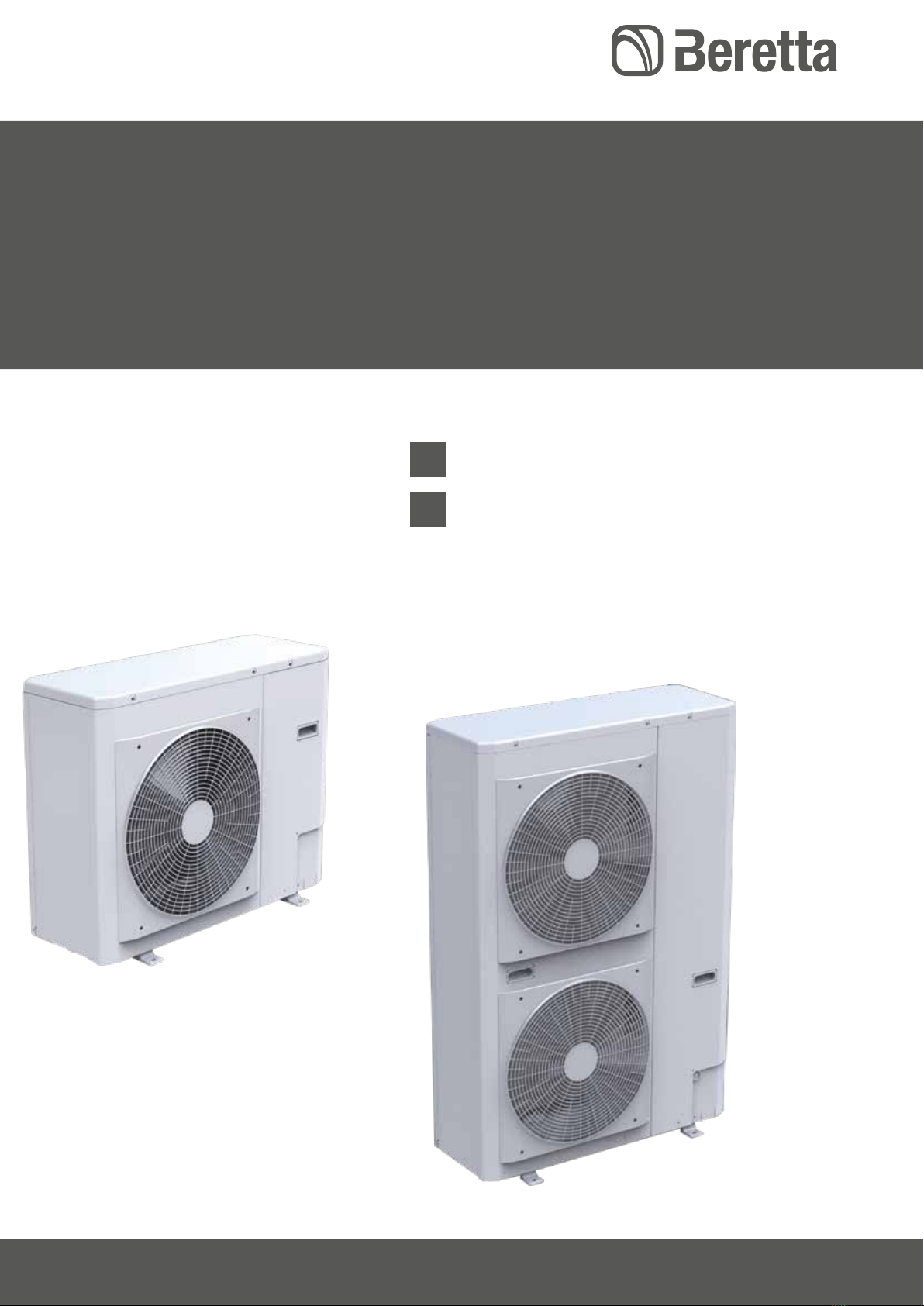
Beretta HYDRONIC UNIT LE 6 Guide

1
HYDRONIC UNIT
Instructions for installation
Installationsvejledning
LE 4 | LE 6 | LE 8 | LE 12
LE 15 | LE 12 T | LE 15 T
EN Instructions for installation
DK Installationsvejledning

HYDRONIC UNIT LE
2 3
Dear client,
Thank you for choosing a BERETTA product.
This booklet provides the information necessary for a correct
and simple installation, without questioning your expertise
and technical competence.
Thank you once again.
CONFORMITY
The appliance complies with the following standards:
Electromagnetic Compatibility Directive 2004/108/EC and
successive modifications
Machine Directive 2006/42/EC and successive
modifications
Directive ErP 2009/125/EC
RANGE
Heat pumps Code
HYDRONIC UNIT LE 4 20099402
HYDRONIC UNIT LE 6 20099403
HYDRONIC UNIT LE 8 20099404
HYDRONIC UNIT LE 12 20099405
HYDRONIC UNIT LE 15 20099406
HYDRONIC UNIT LE 12 T 20099407
HYDRONIC UNIT LE 15 T 20099408
Denne manual indeholder de nødvendige informationer for
korrekt installation af varmepumpen.
KOMPATIBILITET
Dette varmepumpeer produceret i overensstemmelse med
følgende standarder.
El 2004/108/EC
Maskindirektiv 2006/42/EC
ErP 2009/125/EC
MODELLER
Varmepumpe Varenummer
HYDRONIC UNIT LE 4 20099402
HYDRONIC UNIT LE 6 20099403
HYDRONIC UNIT LE 8 20099404
HYDRONIC UNIT LE 12 20099405
HYDRONIC UNIT LE 15 20099406
HYDRONIC UNIT LE 12 T 20099407
HYDRONIC UNIT LE 15 T 20099408
At the end of its life, the product should be not
be disposed of as solid urban waste, but rather it
should be handed over to a differentiated waste
collection centre.
Varmepumpen indeholder kølemiddel og skal
derfor ved nedtagning aeveres til en godkendt
indsamlingsvirksomhed, som er godkendt til at
overtage ansvaret for affald.

HYDRONIC UNIT LE
3
CONTENTS
GENERAL
General warnings................................................................................................................................................................. 5
Basic safety rules................................................................................................................................................................. 6
Description .......................................................................................................................................................................... 7
Identification ........................................................................................................................................................................ 7
Technical Data..................................................................................................................................................................... 9
Performance based on the climatic zone ............................................................................................................................11
Electrical data.....................................................................................................................................................................11
Operating conditions ......................................................................................................................................................... 12
Overall dimensions ........................................................................................................................................................... 13
Wiring diagrams ................................................................................................................................................................ 14
Refrigerating circuit diagram .............................................................................................................................................. 21
INSTALLER
Product delivery................................................................................................................................................................. 22
Handling and transport...................................................................................................................................................... 22
Access to inner parts......................................................................................................................................................... 22
Installation ......................................................................................................................................................................... 23
Hydraulic connections ....................................................................................................................................................... 25
Condensate discharge connection .................................................................................................................................... 27
Electrical wiring.................................................................................................................................................................. 27
Control panel..................................................................................................................................................................... 31
Charging the system.......................................................................................................................................................... 32
Adjustment of the circulation pump.....................................................................................................................................33
TECHNICAL ASSISTANCE CENTRE
First commissioning........................................................................................................................................................... 34
Switching off for lengthy periods........................................................................................................................................ 34
System drainage................................................................................................................................................................ 35
Routine maintenance......................................................................................................................................................... 35
Extraordinary maintenance ................................................................................................................................................ 36
COMMAND
Control panel..................................................................................................................................................................... 38
Functions .......................................................................................................................................................................... 40
FAULTS
Fault signal ........................................................................................................................................................................ 48
Table of user parameters and functions ............................................................................................................................ 52
Table of installer parameters and functions ....................................................................................................................... 54
Table of factory parameters and functions ......................................................................................................................... 56
In some parts of the booklet, various symbols are used:
WARNING = for actions requiring special care and adequate preparation
DO NOT = for actions that SHOULD ON NO ACCOUNT be carried out
This manual Doc-0092372 Ed. 5 (11/18) is made up of 60 pages

HYDRONIC UNIT LE
4
INDHOLDSFORTEGNELSE
GENERELT
Generelt................................................................................................................................................................................5
Sikkerhedsregler...................................................................................................................................................................6
Beskrivelse ...........................................................................................................................................................................7
Identifikation .........................................................................................................................................................................7
Tekniske data .......................................................................................................................................................................9
Ydeevne baseret på klimazone ...........................................................................................................................................11
Elektriske data....................................................................................................................................................................11
Drift betingelser ..................................................................................................................................................................12
Dimensioner .......................................................................................................................................................................13
Ledningsdiagram................................................................................................................................................................14
Køle kredsløbs diagram......................................................................................................................................................21
INSTALLATØR
Levering af produktet..........................................................................................................................................................22
Håndtering og transport .....................................................................................................................................................22
Adgang til indre dele...........................................................................................................................................................22
Installation ..........................................................................................................................................................................23
Forbindelser til varmeanlæg................................................................................................................................................25
Tilslutning til kondensudledning ..........................................................................................................................................27
El forbindelser.....................................................................................................................................................................27
Kontrolpanel .......................................................................................................................................................................31
Udluftning af systemet ........................................................................................................................................................32
Justering af cirkulationspumpe ...........................................................................................................................................33
TEKNISK ASSISTANCE
Første opstart.....................................................................................................................................................................34
Afbrydelse i længere tid ......................................................................................................................................................34
Tømning af anlægget ..........................................................................................................................................................35
Vedligeholdelse...................................................................................................................................................................35
Ekstraordinær vedligeholdelse ............................................................................................................................................36
STYRING
Styrepanel ..........................................................................................................................................................................38
Funktioner ..........................................................................................................................................................................40
FEJL
Fejlkoder.............................................................................................................................................................................48
Funktionstabel og brugerparametre....................................................................................................................................53
Funktionstabel og installatør parametre...............................................................................................................................57
Fabriksindstillinger og funktioner.........................................................................................................................................59
Følgende symboler anvendes i manualen:
ADVARSEL – funktioner, der kræver special viden og omhu.
DO NOT – funktioner, der absolut ikke må udføres
Denne manual Doc-0092372 Ed. 5 (11/18) består af 60 sider

HYDRONIC UNIT LE
5
GENERAL
GENERAL WARNINGS
After removing the packaging, make sure the contents
are complete and undamaged. If necessary contact the
Agency that sold you the appliance.
BERETTA appliances must be installed by authorised compa-
nies in compliance with the DM 37 of 2008 which, at the end
of the job issues the owner with a declaration of conformity
regarding installation, i.e. in compliance with the Standards in
force and the instructions supplied in this booklet.
These appliances should comply with their intended use,
pursuant to their performance characteristics.
BERETTA declines all contractual and non-contractual li-
ability for injury to persons or animal, or damage to prop-
erty, deriving from errors made during installation, adjust-
ment and maintenance, and from improper use.
In the event of abnormal operation, or leaks of liquids or
refrigerant gases, position the main system switch to “off”
and close the stop taps. Call the BERETTA Technical As-
sistance Service immediately, or other professionally quali-
fied personnel. Do not try to repair the appliance.
This booklet should be kept safe as it is an integral part of
the equipment and should ALWAYS be kept with it even
when it is sold or given to someone else to use, or trans-
ferred to another system. Should the booklet get dam-
aged or gets lost, ask for another copy from the local BE-
RETTA Technical Assistance Centre.
Repairs or maintenance work should be carried out by
the BERETTA Technical Assistance Centre, or by quali-
fied personnel, pursuant to the provisions of this booklet.
Do not modify or tamper with the appliance as dangerous
situations can be created and the appliance manufacturer
will not be liable for any damage caused.
In the installation and/or maintenance operations use ap-
propriate clothing and accident prevention equipment.
The Manufacturer declines all responsibility for the failure
to comply with current safety and accident prevention
standards described below.
Comply with the laws of the nation where the machine is
installed with regard to the use and disposal of the pack-
aging, the products used for cleaning and maintenance,
and the unit's decommissioning.
Pursuant to EC 842/2006 standards regarding certain
fluorinated greenhouse gases, it is mandatory to declare
the total amount of refrigerant present in the installed sys-
tem. This information can be found on the technical label
attached to the outdoor unit.
This unit contains fluorinated greenhouse gases covered
by the Kyoto Protocol. Maintenance and disposal activi-
ties should only be carried out by qualified personnel.
The appliances contain refrigerant gases: handle carefully
to avoid damaging the gas circuit.
GENERELT
GENERELT
Kontroller pakkens indhold efter udpakning.
Produktet skal installeres af en autoriseret installatør i
henhold til DM 37 af 2008.
Varmepumpen må kun anvendes til det, den er udviklet til.
Ukorrekt installation kan forårsage skade på personer, dyr
eller ting. Fabrikanten kan ikke gøres ansvarlig for evt. ska-
de der forårsages p.g.a. ukyndiges indgriben i produktet.
I tilfælde af unormal drift, eller lækager af væsker eller køle-
middeludslip. Sluk på ’OFF’ kontakten på systemet og luk
stophanerne. Tilkald kvalificeret teknisk assistance med
det samme. Forsøg ikke at reparere apparatet selv.
Manualen er en integreret del af udstyret og skal ALTID
være tilgængelig ved service eller reparation, samt ved
evt. salg til anden bruger, eller ved ændring af system.
I henhold til bestemmelserne fra denne manual skal re-
parationer eller vedligeholdelse udføres af kvalificererede
installatører. Der må ikke foretages ændring af apparatet,
da det kan medføre farlige situationer. Fabrikant eller in-
stallatør kan ikke stilles ansvar for disse skader.
Ved installation og/eller vedligeholdelse af drift benyttes
passende tøj og sikkerhedsudstyr. Fabrikanten frasiger
sig ansvar for manglende overholdelse af forebyggelse af
ulykker som beskrevet.
Overholdelse af lovene i det pågældende land, hvor pro-
duktet er installeret, er gældende omkring bortskaffelse af
emballage, produkter til brug for rensning og vedligehol-
delse samt nedlukning af unitten.
I henhold til EC 842/2006 standarder vedrørende specielle
fluor drivhusgasser, er det påbudt at deklarere det totale
brug af kølemiddel i det installerede system. Denne infor-
mation kan findes på den tekniske label som er påsat den
udendørs unit.
Enheden indeholder florerede drivhusgasser under Kyoto
Protocol. Vedligeholdelse og bortskaffelse må kun udføres
af kvalificeret personale.
Varmepumpen indeholder kølemiddel gasser: skal be-
handles forsigtigt for at undgå ødelæggelses af gas kreds-
løbet.
Der skal udføre service på varmepumpen en gang om året
af kvalificeret tekniker.
Der skal udføres frostsikring på vandkredsen (frostvæske).

HYDRONIC UNIT LE
6
BASIC SAFETY RULES
This appliance must not be used by children and unaided
disabled persons.
Do not open the access covers to perform any mainte-
nance or cleaning operation before having disconnected
the appliance from the main power supply, by positioning
the master switch at "off".
Do not modify the safety or adjustment devices without
the manufacturer’s authorisation and precise instructions.
Do not climb onto the unit, sit on it and/or rest any type of
object on it.
Do not pull, detach or twist the electrical cables coming
from the unit even if it is disconnected from the main pow-
er supply.
Do not spray or throw water directly onto the unit.
Do not dispose of, abandon or leave potentially hazardous
packing material within the reach of children.
It is absolutely forbidden to touch moving parts, get be-
tween them, or insert pointed objects through the grids.
SIKKERHEDSREGLER
Produktet må ikke betjenes af børn eller andre ukyndige.
Kabinettet på varmepumpen må ikke åbnes før strømmen
er slukket på ‘OFF’. Dette gælder ved udførelse af alle for-
mer for vedligeholdelse.
Modifikationer på varmepumpen må kun foretages af
autoriseret tekniker.
Unitten må ikke benyttes til at sidde/kravle eller lægge ting
på.
Vrid eller træk aldrig til de elektriske kabler fra varmpum-
pen.
Varmepumpen må ikke udsættes for vand eller vandsprøjt.
Efterlad ikke emballage i nærheden af børn.
Det er totalt forbudt at røre de flytbare dele, gå imellem
dem samt indsætte spidse genstande mellem gitrene.

HYDRONIC UNIT LE
7
DESCRIPTION
Hydronic Unit LE
The product is characterised by:
PAM and PWM modulation DC-INVERTER control, which
allows the compressor to modulate its performance con-
tinuously from 30% up to 120%, guaranteeing high ener-
getic standards at any moment.
Pre-painted sheet metal casing.
Revolving ROTARY compressor, for size 4, and TWIN RO-
TARY, for sizes 6-8-12-15, mounted on antivibration sup-
port and placed in a special compartment.
Electronically controlled variable speed fan, ensuring an
extremely silent operation.
AISI 316 stainless steel plate heat exchanger, user side,
insulated with closed cell anti-condensation lining.
Exchanger made of copper pipes and louvered aluminium
fins.
Safety devices like sensors, specific automatic switches.
Integrated hydronic module, providing a rapid installation
with the help of a few external components.
Micro-processor electronic control regulating the opera-
tion.
Climate control.
The Hydronic Unit LE appliances are used for the production
of refrigerated water for air conditioning, hot water for heating
and domestic hot water for homes, commercial units and the
like, and are used together with terminal units on small and
medium systems.
Designed for outdoor use, the materials employed have been
chosen for this specific requirement.
IDENTIFICATION
Technical Tag
The technical label shows all the appliance's technical and
performance data. If it gets lost, ask for a copy from the
BERETTA Technical Assistance Centre.
Tampering, removal, lack of identification labels or any-
thing else which does not permit the safe identification of
the product, makes any installation and maintenance op-
eration difficult.
BESKRIVELSE
Hydronic Unit LE
PAM og PWN modulerings DC-INVERTER kontrol, der la-
der kompressoren modulere kontinuerligt fra 30% op til
120%. Dette garanterer høj energi-standard til enhver tid.
Pulverlakeret kabinet.
For enhed 4 er en enkel roterende ROTARY-type kom-
pressor og en Roterende TWIN ROTARY-type kompres-
sor for enhed 6-8-12-15. Disse er monteret på antivibre-
rende konsol og placeret separat.
Elektronisk kontrolleret variabel hastighedsblæser, der
sikrer lydsvag funktion.
AISI 316 varmeveksler rustfri stålplade, bruger side, isole-
ret med antikondenserende foring.
Veksler fremstillet af kobberrør og aluminiums lameller.
Sikkerhedsudstyr så som følere, specifikke automatiske
kontakter.
Mikroprocessor elektronisk kontrol regulerings funktion.
Klima kontrol.
Hydronic Unit LE produkterne er udviklet til nedkøling af vand
til aircondition, opvarmning af vand og varmt brugsvand. Den
anvendes sammen med terminale enheder til små og mel-
lemstore anlæg.
Den er udviklet til udendørs installation og materialerne er
valgt dertil.
IDENTIFIKATION
Datapladen viser alle enhedens tekniske data samt ydeev-
ne. Denne label må ikke fjernes.
Hvis labelen mangler vanskeliggøres identifikation, instal-
lation og service af produktet.

HYDRONIC UNIT LE
8
1Automatic air vent valve
2Temperature probe
3Safety valve (output 1/2’)
4Recirculation pump
5Cap to release pump seizure
6Flow meter
7Expansion tank
1Automatisk luftudlader
2Temperatur føler
3Sikkerhedsventil ½’
4Cirkulationspumpe
5Dæksel på pumpe
6Flowmåler
7Ekspansionsbeholder
4 - 6 - 8 12 - 15
1
1
2
3
2
3
6
7
5
4
4
7
6
4 - 6 - 812 - 15

HYDRONIC UNIT LE
9
TECHNICAL DATA
Reference conditions
Sound pressure measured in a hemispheric field 4 metres
in front of the fan.
Unit performances have been provided in reference to
Directive UNI EN 14511:2011.
Fouling factor: 0.18 x 10⁻⁴ (m² K)/W.
Model
HYDRONIC
UNIT LE 4 HYDRONIC
UNIT LE 6 HYDRONIC
UNIT LE 8 HYDRONIC
UNIT LE 12 HYDRONIC
UNIT LE 15 HYDRONIC UNIT
LE 12 T
HYDRONIC
UNIT LE
15 T
Performance in heating mode
Nominal capacity (1) kW 4,07 5,76 7,16 11,86 14,46 12 15
Power consumption (1) kW 0,98 1,35 1,80 3,00 3,54 2,79 3,57
COP (1) 4,15 4,28 3,97 3,95 4,09 4,30 4,20
Nominal capacity (2) kW 3,87 5,76 7,36 12,91 13,96 11,2 14,5
Power consumption (2) kW 1,19 1,89 2,31 4,26 4,32 3,34 4,39
COP (2) 3,26 3,05 3,19 3,03 3,23 3,35 3,30
Nominal capacity (3) kW 3,5 3,8 4,1 8 10,2 8,55 9,5
Power consumption (3) kW 1,13 1,23 1,31 2,6 3,29 2,69 3,02
COP (3) 3.1 3.1 3.1 3.1 3.1 3,17 3,15
Nominal capacity (4) kW 3,4 3,7 3,9 8 10,2 7,5 9,3
Power consumption (4) kW 1,31 1,42 1,48 3,08 3,92 2,78 3,50
COP (4) 2,6 2,6 2,6 2,6 2,6 2,70 2,65
Nominal capacity (5) kW 4,1 5,4 6,7 11,5 11,7 11,05 12
Power consumption (5) kW 1,51 2,09 2,91 4,64 4,18 3,95 4,21
COP (5) 2,71 2,58 2,3 2,48 2,8 2,80 2,85
Nominal capacity (6) kW 4,27 5,43 7,25 10,87 12,36 11,43 12,17
Power consumption (6) kW 1,46 1,95 2,58 4,05 4,09 3,66 4,08
COP (6) 2,92 2,77 2,81 2,68 3,02 3,12 2,98
Capacity (7) kW 1,06 1,50 1,86 4,68 4,78 4,78 4,78
COP (7) 2,75 2,82 2,81 2,70 2,75 2,75 2,75
Performance in cooling mode
Nominal capacity (8) kW 4,93 7,04 7,84 13,54 16,04 13,5 16
Power consumption (8) kW 1,17 1,90 1,96 3,70 4,17 3,25 4,20
EER (8) 4,2 3,7 3,99 3,66 3,85 4,15 3,81
Nominal capacity (9) kW 3,33 4,73 5,84 10,24 13,04 10,2 13
Power consumption (9) kW 1,10 1,58 1,96 3,46 4,42 3,40 4,47
EER (9) 3,02 3 2,98 2,96 2,95 3 2,91
ESEER (9) 4,36 4,51 4,15 4,22 4,31 4,40 4,31
Generalities
Sound pressure in heating mode dB(A) 42 42 44 47 48 48 48
Sound pressure in cooling mode dB(A) 44 44 45 48 49 49 49
Compressor
ROTARY DC INV.
TWIN ROTARY DC INVERTER
R410a refrigerant charge ** kg 1,195 1,35 1,81 2,45 3,39 3,385 3,385
Empty weight kg 57 61 69 104 112 116 116
Number of fans n 1 1 1 2 2 2 2
Fan diameter mm 495 495 495 495 495 495 495
Water circuit
Static pressure available kPa 60 60 56 70 58 70 55
Expansion tank capacity l 2223333
Expansion tank pre-charge kPa 200 200 200 200 200 200 200
System minimum water volume l 14 21 28 42 49 42 49
System maximum water volume * l 65 65 65 95 95 95 95
Machine water volume l 0,8 0,8 1,0 2,3 2,3 2,3 2,3
Maximum operating pressure kPa 300 300 300 300 300 300 300
Minimum filling pressure kPa 120 120 120 120 120 120 120
Hydraulic connections diameter Inches 1M 1M 1 M 1 M 1 M 1M 1M
* For greater water volumes it is necessary to provide an additional expansion tank
** The value of the refrigerant charge is indicative. The correct value is indicated on the technical data plate.
Note / Note
1outdoor temperature d.b. + 7 °C / w.b. + 6°C, water 35 - 30 °C.
2outdoor temperature + 7 °C / w.b. + 6°C, water 45 - 40 °C.
3outdoor temperature d.b. + 2 °C / w.b. +1°C, water 35 - 30 °C.
4outdoor temperature d.b. + 2 °C / w.b. +1°C, water 45 - 40 °C.
5outdoor temperature d.b. + 7 °C / w.b. + 6°C, water 55 °C.
6
outdoor temperature d.b. + 7 °C / d.b. + 6°C, water 47 - 55 °C.
EN 14511
7outdoor temperature -7 °C, water 35 °C (with rated water flow)
8outdoor temperature d.b. +35 °C / w.b. +24°C, water 18 - 23 °C.
9outdoor temperature d.b. +35 °C, water 7 - 12 °C.
d.b. dry bulb
w.b. wet bulb

HYDRONIC UNIT LE
10
TEKNISKE DATA
Lydniveau målt i hemisfærisk område 4 meter fra blæser.
Funktioner i overensstemmelse med UNI EN 14511:2011.
Forureningsfaktor: 0,18 x 10⁻⁴ (m2K)/W.
Model
HYDRONIC
UNIT LE 4 HYDRONIC
UNIT LE 6 HYDRONIC
UNIT LE 8 HYDRONIC
UNIT LE 12 HYDRONIC
UNIT LE 15 HYDRONIC UNIT
LE 12 T
HYDRONIC
UNIT LE
15 T
Varmefunktion
Nominel ydelse (1) kW 4,07 5,76 7,16 11,86 14,46 12 15
El forbrug (1) kW 0,98 1,35 1,80 3,00 3,54 2,79 3,57
COP (1) 4,15 4,28 3,97 3,95 4,09 4,30 4,20
Nominel ydelse (2) kW 3,87 5,76 7,36 12,91 13,96 11,2 14,5
El forbrug (2) kW 1,19 1,89 2,31 4,26 4,32 3,34 4,39
COP (2) 3,26 3,05 3,19 3,03 3,23 3,35 3,30
Nominel ydelse (3) kW 3,5 3,8 4,1 8 10,2 8,55 9,5
El forbrug (3) kW 1,13 1,23 1,31 2,6 3,29 2,69 3,02
COP (3) 3.1 3.1 3.1 3.1 3.1 3,17 3,15
Nominel ydelse (4) kW 3,4 3,7 3,9 8 10,2 7,5 9,3
Elforbrug (4) kW 1,31 1,42 1,48 3,08 3,92 2,78 3,50
COP (4) 2,6 2,6 2,6 2,6 2,6 2,70 2,65
Nominel ydelse (5) kW 4,1 5,4 6,7 11,5 11,7 11,05 12
Elforbrug (5) kW 1,51 2,09 2,91 4,64 4,18 3,95 4,21
COP (5) 2,71 2,58 2,3 2,48 2,8 2,80 2,85
Nominel ydelse (6) kW 4,27 5,43 7,25 10,87 12,36 11,43 12,17
El forbrug (6) kW 1,46 1,95 2,58 4,05 4,09 3,66 4,08
COP (6) 2,92 2,77 2,81 2,68 3,02 3,12 2,98
Kapacitet (7) kW 1,06 1,50 1,86 4,68 4,78 4,78 4,78
COP (7) 2,75 2,82 2,81 2,70 2,75 2,75 2,75
Kølefunktion
Nominel ydelse (8) kW 4,93 7,04 7,84 13,54 16,04 13,5 16
El forbrug (8) kW 1,17 1,90 1,96 3,70 4,17 3,25 4,20
EER (8) 4,2 3,7 3,99 3,66 3,85 4,15 3,81
Nominel ydelse (9) kW 3,33 4,73 5,84 10,24 13,04 10,2 13
El forbrug (9) kW 1,10 1,58 1,96 3,46 4,42 3,40 4,47
EER (9) 3,02 3 2,98 2,96 2,95 3 2,91
ESEER (9) 4,36 4,51 4,15 4,22 4,31 4,40 4,31
Generelt
Lydniveau i varmefunktion dB(A) 42 42 44 47 48 48 48
Lydniveau i kølefunktion dB(A) 44 44 45 48 49 49 49
Kompressor
ROTARY DC INV.
TWIN ROTARY DC INVERTER
R410a kølemiddel** kg 1,195 1,35 1,81 2,45 3,39 3,385 3,385
Netto vægt kg 57 61 69 104 112 116 116
Antal blæsere Stk 1 1 1 2 2 2 2
Blæser Diameter mm 495 495 495 495 495 495 495
Vandkredsløb
Statisk tilgængelig tryk kPa 60 60 56 70 58 70 55
Ekspansionsbeholder kapacitet l 2223333
Ekspansionsbeholder fortryk kPa 200 200 200 200 200 200 200
Min vandproduktion l 14 21 28 42 49 42 49
Max vandproduktion* l 65 65 65 95 95 95 95
UNIT vandindhold l 0,8 0,8 1,0 2,3 2,3 2,3 2,3
Max. arbejdstryk kPa 300 300 300 300 300 300 300
Min. arbejdstryk kPa 120 120 120 120 120 120 120
Rørforbindelser Zoll 1M 1M 1 M 1 M 1 M 1M 1M
* For større vandproduktion er det nødvendigt at tilslutte en ekstra ekspansionstank
** Værdien af kølemiddel er vejledende. Den korrekte værdi vises på datapladen.
1Udetemperatur d.b. +7°C/w.b. +6°C, vand 35 – 30°C
2Udetemperatur +7°C/w.b. +6°C, vand 45 – 40°C
3Udetemperatur D.b. +2°C/w.b. +1°C, vand 35 – 30°C
4
Udetemperatur D.b. +2°C/w.b. +1°C, vand 45 – 40°C
5Udetemperatur D.b. +7°C/w.b. +6°C, vand 55°C
6Udetemperatur D.b. +35°C/w.b. 24°C, vand 18 – 23°C
7Udetemperatur D.b. +35°C, vand 7 – 120°C
d.b.
Tør
w.b. Fugtig
Standard forhold

HYDRONIC UNIT LE
11
Model / Modell HYDRONIC
UNIT LE 4
HYDRONIC
UNIT LE 6
HYDRONIC
UNIT LE 8
HYDRONIC
UNIT LE 12
HYDRONIC
UNIT LE 15
HYDRONIC
UNIT LE
12 T
HYDRONIC
UNIT LE
15 T
Temperate zone - Average temperature (47 / 55 °C) - Tempereret zone - Gennemsnitstemperatur (47 / 55°C)
ŋs138 132 111 115 127 136 130
SCOP 3,53 3,37 2,84 2,95 3,25 3,47 3,33
Pdesign kW 3,28 4,22 4,65 8,68 9,05 8,38 9,37
Annual consumption * / Årligt forbrug* kW/h 1.900 2.571 3.367 6.077 5.748 4.975 5.806
Energy class / Energi Klasse A++ A++ A+ A+ A++ A++ A++
Cold zone - Average temperature (47 / 55 °C) / Kold zone – gennemsnitstemperatur (47 / 55°C)
ŋs126 112 103 106 119 121 122
SCOP 3,23 2,87 2,64 2,72 3,06 3,09 3,11
Pdesign kW 5,16 6,65 6,59 13,67 14,52 13,20 15,05
Annual consumption * / Årligt forbrug* kW/h 3.911 5.431 5.867 11.859 11.188 10.060 11.404
Warm zone - Average temperature (47 / 55 °C) / Varm zone – gennemsnitstemperatur (47 / 55°C)
ŋs190 181 152 158 175 187 179
SCOP 4,82 4,60 3,88 4,03 4,44 4,74 4,55
Pdesign kW 3,10 3,79 4,83 8,04 8,38 7,76 8,67
Annual consumption * / Årligt forbrug* kW/h 843 1.085 1.649 2.651 2.508 2.177 2.537
Temperate zone - Low temperature (30 / 35 °C) /Tempereret zone – lavt temperatur 30 / 35°C)
ŋs146 141 118 125 141 148 144
SCOP 3,73 3,60 3,03 3,19 3,61 3,78 3,68
Pdesign kW 3,83 4,92 4,56 10,00 10,75 9,76 11,12
Annual consumption * / Årligt forbrug* kW/h 2.015 2.806 3.088 6.467 6.137 5.314 6.230
Energy class / Energi Klasse A+ A+ A A+ A+ A+ A+
Cold zone - Low temperature (30 / 35 °C) / Kold zone – lav temperatur (30 / 35°C)
ŋs133 120 110 115 133 132 135
SCOP 3,41 3,07 2,82 2,94 3,40 3,37 3,44
Pdesign 6,03 7,75 6,46 15,75 17,25 15,37 17,86
Annual consumption * / Årligt Forbrug kW/h 4.148 5.927 5.381 12.620 11.945 10.741 12.237
Warm zone - Low temperature (30 / 35 °C) / Varm zone – Lav temperatur (30 / 35°C)
ŋs201 194 163 171 194 203 198
SCOP 5,09 4,92 4,14 4,36 4,93 5,16 5,03
Pdesign kW 3,42 4,06 5,09 9,20 9,96 9,04 10,29
Annual consumption * / Årligt forbrug* kW/h 880 1.084 1.624 2.809 2.681 2.327 2.714
Noise level / Lydniveau
Sound power / Lydniveau dB(A) 62 62 64 67 68 68 68
PERFORMANCE BASED ON THE CLIMATIC ZONE LEISTUNGSWERTE IN BEZUG AUF DIE KLIMAZONE
* With backup electric heater * Med elektrisk varme backup
Modello 4 6 8 12 15 12T 15T
Power supply V- ph - Hz 230 - 1 -50 400 - 3 -50
Allowable voltage range V 207 ÷ 254 373 ÷ 424
Maximum power drawn kW 2 2,3 3,7 5,1 5,1 6,5 6,5
Maximum current drawn A 7,2 11 14 23 20 16 16
Type of fuses gL type
Power supply fuses current A 10- type B 16- type B 16- type B 25 - type D 25 - type D 16- type B 16- type B
Power supply cables mm2H07RN-F 3 x 2.5mm2H07RN-F 5 x 2.5mm2
Maximum p
ump current external circulatio
n A 2
Use H03VV-F 4x0.75 mm² cables to connect the remote control to the wires
Model 4 6 8 12 15 12T 15T
El tilslutning V- PH - Hz 230 - 1 -50 400 - 3 -50
Volt V 207 ÷ 254 373 ÷ 424
Max. strøm input kW 2 2,3 3,7 5,1 5,1 6,5 6,5
Max. strømforbrug A 7,2 11 14 23 20 16 16
Sikringer Betriebsklasse gL
Sikringer el A 10 - Typ B 16 - Typ B 16 - Typ B 25 - Typ D 25 - Typ D 16 - Typ B 16 - Typ B
Elkabler mm2H07RN-F 3 x 2.5mm2H07RN-F 5 x 2.5mm2
Max. ekstern. cirkulationspumpe A 2
Benyt H03W-F 4X0,75 mm2 kabler for at forbinde fjernbetjeningen til ledningerne
ELECTRICAL DATA ELEKTRISKE DATA

HYDRONIC UNIT LE
1212
OPERATING CONDITIONS
Heat pump optimal operation when producing DHW
should have an outdoor air temperature that does not ex-
ceed 30°C.
For outdoor air temperatures exceeding 30°C the domes-
tic hot water production may be limited due to the inter-
vention of machine safety devices.
For technical interventions, see the technical label on the
machine.
It is forbidden to work outside firing rate.
1Cooling
2Heating
A Outdoor air temperature (°C)
BOutput water temperature (°C)
Flow rate-discharge head diagram
A Flow rate (l/s)
BAvailable static pressure (kPa)
12
10
15
20
25
30
35
40
45
50
55
60
65
70
-25-20 -15-10 -5 0510 15 20 25 30 35
A
B
A
B
0
2
4
6
8
10
12
14
16
18
20
-5 0510 15 20 25 30 35 40 45 50
008-012-015
004
006
DRIFT BETINGELSER
For optimal funktion af varmepumpen ved produktion af
varmt vand i sommerfunktion, må udetemperaturen ikke
overstige 30°C.
Hvis udetemperaturen overstiger 30°C er varmvandspro-
duktionen begrænset af apparatets sikkerhedsanordning.
For tekniske foranstaltninger henvises til datapladen på
produktet.
Indstillinger udenfor de angivne funktionsområder er ikke
tilladt.
1Køling
2Opvarmning
A Udetemperatur (°C)
BFremløbstemperatur (°C)
Flowmåler
A Flow hastighed (I/s)
BTilgængelig statisk tryk (kPa)
0,10,0
75
65
B
A
4 6
55
45
35
25
15
5
75
65
B
55
45
35
25
15
5
0,2 0,3 0,4 0,5 0,10,0
A
0,2 0,3 0,4 0,5 0,6

HYDRONIC UNIT LE
139
OVERALL DIMENSIONS / DIMENSIONER
Model
Model 4 6 8 12 15 12 T 15 T
Overall dimensions / Dimensioner
Empty weight
Netto vægt kg 57 61 69 104 112 116 116
A mm 908
B mm 821 1363
C mm 326
D mm 350
E mm 87 174
F mm 356 640
G mm 466 750
H mm 40 44
L mm 60 69
60015
41
54
430
400
363
37
1
2
3
60015
41
54
430
400
363
37
1
2
3
75
65
B
812 - 15
55
45
35
25
15
5
85
95
75
B
65
55
45
35
25
15
0,10,0
A
0,2 0,3 0,4 0,5 0,6 0,7 0,10,0
A
0,2 0,3 0,4 0,5 0,6 0,7 0,8 0,9 1,0

HYDRONIC UNIT LE
14
-Wiring of the manufacturer
---- Wiring of the installer
CM Compressor motor
FM Fan motor
RV Reversing valve (4 way)
TS Temperature probe low pressure pipe
TO Temperature probe external unit
TD Temperature probe high pressure pipe
TE Temperature probe capacitor pipe
PMV Modulating valve motor
RReactor
FFuse
LWT Water outlet probe
EWT N.A.
TR Refrigerant sensor
FS Flow meter
TL Temperature probe capacitor pipe 2
CCompressor thermostat
HHigh pressure switch
RY Relay
TTransformer
PS Water pump motor
E-HTR Electric heater
AD Alarm status and defrost
OAT Outside air probe
LF Frequency Limiting
IS Domestic water input
SV Three-way domestic water valve
YYellow
OOrange
RRed
GGrey
A Brown
C Black
VViolet
BBlue
WWhite
Y/G Yellow Green
WIRING DIAGRAMS
-Fabriksmonteret
---- Monteret ved installation
CM Kompressor motor
FM Blæsermotor
RV Omskiftet ventil (4 vejs)
TS Temperaturføler lavtryksrør
TO Temperaturføler ekstern enhed
TD Temperaturføler højtryksrør
TE Temperaturføler kondensafløb
PMV Modulerende blæsermotor
RReaktor
FSikring
LWT Fremløbsføler
EWT Anvendes ikke
TR Føler afkøling
FS Flowmeter
TL Temperaturføler kondensafløb 2
CKompressor termostat
HHøjtryks kontakt
RY Relæ
Transformer
TVandpumpemotor
PS El-varmeelement
E-HTR Alarm status og afrimning
AD Udeføler
OAT Frekvensgrænse
LF Brugsvands input
IS 3-vejs brugsvandsventil
SV Gul
YOrange
ORød
RGrå
GBrun
A Sort
C Violet
VBlå
BHvid
WGul/grøn
Y/G Gelb-grün
LEDNINGSDIAGRAM

HYDRONIC UNIT LE
15
HYDRONIC UNIT LE 4 POWER/HYDRONIC UNIT LE 4 FORBINDELSESDIAGRAM
HYDRONIC UNIT LE 4 CONTROL / HYDRONIC UNIT LE 4 FORBINDELSESDIAGRAM
R
R
W
W
C
C
Y
A
Y
Y
R
W
C
V
C
C
W
O
C
W
R
A
C
C
Y/G
B
W
W
Y/G
Y/G
C
A
B
1FM
1CM
R
S
C
1CF
1 2 3
2CM 1 2 3
THERMOSTATFOR
COMPRESSOR
1R
2CF
2 1
3CM 2 1
1T 12
P25
P24
P23
P22
P21
P20
P35
P34
P19
P18
P04
P05
P06
1P.C.BOARD
P11
P08
1MCC1530
3CF 1 2 3
4CF 1 2 3
CN805
1
1
P33
2R
P32
5CF
2 1
4CM 2 1
P31
/2.10/J4.1
P30
CN701
/2.03/J3.1
6CF
1 2 3
1
/2.08/J1.1
1RV
F7 P03 P10 P02
CN806
1
CN300
CN700
CN503
CN502
CN501
CN500
1TB
1
1
6
1
1
1
1
1
N
7CF
3
2
1
8CF
6
5
4
3
2
1
9CF
3
2
1
10CF
2
1
11CF
3
2
1
12CF
2
1
3 L NPE
1TS
1TO
1TD
1TE
1PMV
1FL U1 U3
L2 N4
PE
N
L
230V1~50Hz
G
B
Y/G
Y/G
R
RA
B
C
A
Y/G
A
O
W
G
Y
C
R
C
W
W
RG
A
C
C
O
A
B
B
B
A
G
C
OG
R
1PS
1LWT
5CM
1
2
3
13CF
1
2
3
1TR
/1.05/J3.1
1SV
1PCB
15CF
1
2
16CF
1
2
17CF 1
2
18CF 7
6
5
4
3
2
1
J6A.1
J6A.2
J6B.1
J6B.2
J6B.1
J6B.2
J18.1
J18.2
J11.7
J11.6
J11.5
J11.4
J11.3
J11.2
J11.1
1
19CF
123456
J16.1
1
1
1
1
1
J18
J11
1
J16.2
20CF
12345
J6A
J6B
J6C
ALARM+
DFR
/
HUMIDITY
J5.1
J16.3
J16
J5.2
J16.4
EHTR
/
WP
J5.3
J5
J16.5
J5.4
J16.6
J5.5
21CF
7654321
J20.7
REMOTE
J20.6
1FS
1
2
22CF
1
2
1
J15.1
J20.5
J15
J17.1
J17.2
J10.1
J20.4
J20
1
J10.2
J20.3
J17
J10.3
J20.2
J10
1OAT
J10.4
J20.1
1
J10.5 J10.6
23CF
1 2 3 4
1
J22.1 J22.2
J22
1
J22.3
24CF
1 2 3
J13.1
J22.4
J13.2
J13
2T
J13.3
1
J7
25CF
123456
EHS
/
DFR
J7.1
1
26CF
1 2 3
J2.1
J7.2
ALARM
J2.2
J7.3
J2
J2.3
J7.4 J7.5 J7.6
J1.1
J1.1//1.05
J1
1LF
1
2
1
J4
27CF
12345
J4.1 J4.2
1IS
1
2
J4.3 J4.4
ALARM
INPUT
J4.5
J3
J4.1//1.05
REMOTE
CONTROL
2TB
CWGY13 14 15 7 6 3 2 1 8 21 23 24
3TB
N N 18 10 11 12 4 5 16

HYDRONIC UNIT LE
16
HYDRONIC UNIT LE 6 Power / HYDRONIC UNIT LE 6 FORBINDELSESDIAGRAM
HYDRONIC UNIT LE 6 CONTROL / HYDRONIC UNIT LE 6 FORBINDELSESDIAGRAM
R
R
W
W
C
C
Y
A
Y
Y
R
W
C
V
C
C
W
O
C
W
R
A
C
C
Y/G
B
W
W
Y/G
Y/G
C
A
B
1FM
1CM
R
S
C
1CF
1 2 3
2CM 1 2 3
THERMOSTATFOR
COMPRESSOR
1R
2CF
2 1
3CM 2 1
1T 12
P25
P24
P23
P22
P21
P20
P35
P34
P19
P18
P04
P05
P06
1P.C.BOARD
P11
P08
1MCC1530
3CF 1 2 3
4CF 1 2 3
CN805
1
1
P33
2R
P32
5CF
2 1
4CM 2 1
P31
/2.10/J4.1
P30
CN701
/2.03/J3.1
6CF
1 2 3
1
/2.08/J1.1
1RV
F7 P03 P10 P02
CN806
1
CN300
CN700
CN503
CN502
CN501
CN500
1TB
1
1
6
1
1
1
1
1
N
7CF
3
2
1
8CF
6
5
4
3
2
1
9CF
3
2
1
10CF
2
1
11CF
3
2
1
12CF
2
1
3 L NPE
1TS
1TO
1TD
1TE
1PMV
1FL U1 U3
L2 N4
PE
N
L
230V1~50Hz
G
B
Y/G
Y/G
R
RA
B
C
A
Y/G
A
O
W
G
Y
C
R
C
W
W
RG
A
C
C
O
A
B
B
B
A
G
C
OG
R
1PS
1LWT
5CM
1
2
3
13CF
1
2
3
1TR
/1.05/J3.1
1SV
1PCB
15CF
1
2
16CF
1
2
17CF 1
2
18CF 7
6
5
4
3
2
1
J6A.1
J6A.2
J6B.1
J6B.2
J6B.1
J6B.2
J18.1
J18.2
J11.7
J11.6
J11.5
J11.4
J11.3
J11.2
J11.1
1
19CF
123456
J16.1
1
1
1
1
1
J18
J11
1
J16.2
20CF
12345
J6A
J6B
J6C
ALARM+
DFR
/
HUMIDITY
J5.1
J16.3
J16
J5.2
J16.4
EHTR
/
WP
J5.3
J5
J16.5
J5.4
J16.6
J5.5
21CF
7654321
J20.7
REMOTE
J20.6
1FS
1
2
22CF
1
2
1
J15.1
J20.5
J15
J17.1
J17.2
J10.1
J20.4
J20
1
J10.2
J20.3
J17
J10.3
J20.2
J10
1OAT
J10.4
J20.1
1
J10.5 J10.6
23CF
1 2 3 4
1
J22.1 J22.2
J22
1
J22.3
24CF
1 2 3
J13.1
J22.4
J13.2
J13
2T
J13.3
1
J7
25CF
123456
EHS
/
DFR
J7.1
1
26CF
1 2 3
J2.1
J7.2
ALARM
J2.2
J7.3
J2
J2.3
J7.4 J7.5 J7.6
J1.1
J1.1//1.05
J1
1LF
1
2
1
J4
27CF
12345
J4.1 J4.2
1IS
1
2
J4.3 J4.4
ALARM
INPUT
J4.5
J3
J4.1//1.05
REMOTE
CONTROL
2TB
CWGY13 14 15 7 6 3 2 1 8 21 23 24
3TB
N N 18 10 11 12 4 5 16

HYDRONIC UNIT LE
17
HYDRONIC UNIT LE 8 POWER / HYDRONIC UNIT LE 8 FORBINDELSESDIAGRAM
HYDRONIC UNIT LE 8 CONTROL / HYDRONIC UNIT LE 8 FORBINDELSESDIAGRAM
R
R
W
W
C
C
Y
A
Y
Y
R
W
C
V
C
C
W
R
O
RA
C
B
W
W
C
WW
R
C
Y/G Y/G
Y/G
B
A
C
1FM
6CM
R
S
C
40CF
1 2 3
7CM 1 2 3
THERMOSTATFOR
COMPRESSOR
1R
41CF
2 1
8CM 2 1
2T 12
P25
P24
P23
P22
P21
P20
P35
P34
P19
P18
P04
P05
P06
1P.C.BOARD
P11
P08
1MCC1530
42CF 1 2 3
43CF 1 2 3
CN805
1
1
P33 P32
2R
44CF
2 1
9CM 2 1
P31 P30
CN701
45CF
1 2 3
1
1RV
F7 P03
1F
1 2
P10 P02
CN806
1
CN300
CN700
CN503
CN502
CN501
CN500
3R
1TB
1
1
6
1
1
1
1
1
N
46CF
3
2
1
47CF
6
5
4
3
2
1
48CF
3
2
1
49CF
2
1
50CF
3
2
1
51CF
2
1
3 L NPE
1TS
1TO
1TD
1TE
1PMV
N
L
230V1~50Hz
/2.10/J4.1
/2.03/J3.1
/2.08/J1.1
1FL U1 U3
L2 N4
PE
G
B
Y/G
Y/G
B
Y/G
OW
R
R
G
A
Y
G
C
A
O
B
A
C
R
C
G
W
W
R
R
B
G
AA
C
C
O
A
B
C
1PS
1LWT
10CM
1
2
3
52CF
1
2
3
1TR
/1.05/J3.1
2TB
N N 18
1SV
1PCB
54CF
1
2
55CF
1
2
56CF 1
2
57CF 7
6
5
4
3
2
1
10
J6A.1
J6A.2
J6B.1
J6B.2
J6B.1
J6B.2
J18.1
J18.2
J11.7
J11.6
J11.5
J11.4
J11.3
J11.2
J11.1
1
58CF
123456
J16.1
1
1
1
1
1
J18
J11
1
J16.2
59CF
12345
J6A
J6B
J6C
11
ALARM+
DFR
/
HUMIDITY
J5.1
J16.3
J16
J5.2
J16.4
EHTR
/
WP
12
J5.3
J5
J16.5
J5.4
EHS
/
DFR
J16.6
4
J5.5
60CF
7654321
J20.7
ALARM
5
J20.6
1FS
1
2
61CF
1
2
1
J15.1
J20.5
J15
J17.1
J17.2
16
J10.1
J20.4
J20
1
J10.2
J20.3
J17
J10.3
J20.2
J10
J10.4
J20.1
1
J10.5 J10.6
62CF
1 2 3 4
1
3TB
J22.1
C
J22.2
J22
1
J22.3
63CF
1 2 3
REMOTE
J13.1
W
J22.4
J13.2
J13
3T
J13.3
G
1
J7
64CF
123456
J7.1
1
Y
65CF
1 2 3
J2.1
J7.2
J2.2
J7.3
J2
13
J2.3
J7.4 J7.5
1LF
1
2
14
J7.6
1IS
1
2
15
J1.1
J1.1//1.05
J1
1
7
J4
66CF
12345
J4.1 J4.2
6
J4.3
REMOTE
CONTROL
J4.4
3
J4.5
J3
2 1 8
J4.1//1.05
ALARM
INPUT
21 23 24
1OAT

HYDRONIC UNIT LE
18
HYDRONIC UNIT LE 12 POWER/HYDRONIC UNIT LE 12 FORBINDELSESDIAGRAM
HYDRONIC UNIT LE 12 CONTROL / HYDRONIC UNIT LEE 12 FORBINDELSESDIAGRAM
R
W
C
Y/G
W
R
W
G
C
G
O
OA
PRB
C
W
CY
Y
B
B
O
O
C
W
R
W
W
C
C
A
R
R
B
1TB
PE
230V1~50Hz
1F
1
2
L
L
1RV
N
N
1CF
1
2
3
2CF
1
2
3
4
5
CN01
CN02
CN03
1P.C.BOARD
2P.C.BOARD
1CM
1 2 3
3CF 1 2 3
P08
1
CN700
1
CN02
4CF 12345
5CF 12345
1
1
1PVM
6CF 123456
2TB
1
P09
1
R
CN13
CN01
CN702
2CM
1 2 3
7CF 1 2 3
P12
N
P13
R
1
8CF 1 2
9CF
1 2
1
CN05
CN04
3
P21
10CF 1 2 3
1CN303
P24
1
11CF 12345
12CF
12345
1
+
1FM
CN800
CN06
P28
J4.1//2.10
J3.1//2.03
J1.1//2.08
P29
13CF 12345
ED
1CN302
1
14CF 1 2 3
15CF
1 2 3
1
P19
CN04
CN03
P20 P17 P18
CN600
1
16CF 1 2 3
1
17CF
1
2
CN09
CN10
CN11
CN301
2FM
1TH
1TD
18CF
1 2 3
1CN600
19CF 12345
1CN300
20CF
1 2
1
1TS
CN605
21CF
1 2
1
1TE
CN604
22CF
1 2
THERMOSTAT
FORCOMPRESSOR
1CN500
1T
1
2
23CF
1 2 3
1CN601
1TO
1CN606
3CM
R
C
S
1
3
2
4
1FL
G
B
Y/G
Y/G
Y/G
O
W
R
R
G
A
Y
A
B
A
C
R
C
W
W
RG
A
C
C
O
C
G
C
B
RG
BA
O
B
A
1PS
1LWT
4CM
1
2
3
24CF
1
2
3
1TR
/1.05/J3.1
3TB
N N 18
1SV
1PCB
26CF
1
2
27CF
1
2
28CF 1
2
29CF 7
6
5
4
3
2
1
10
J6A.1
J6A.2
J6B.1
J6B.2
J6B.1
J6B.2
J18.1
J18.2
J11.7
J11.6
J11.5
J11.4
J11.3
J11.2
J11.1
1
30CF
123456
J16.1
1
1
1
1
1
J18
J11
1
J16.2
31CF
12345
J6A
J6B
J6C
11
ALARM+
DFR
/
HUMIDITY
J5.1
J16.3
J16
J5.2
J16.4
EHTR
/
WP
12
J5.3
J5
J16.5
J5.4
EHS
/
DFR
J16.6
4
J5.5
32CF
7654321
J20.7
ALARM
5
J20.6
1FS
1
2
33CF
1
2
1
J15.1
J20.5
J15
J17.1
J17.2
16
J10.1
J20.4
J20
1
J10.2
J20.3
J17
J10.3
J20.2
J10
J10.4
J20.1
1
J10.5 J10.6
34CF
1 2 3 4
1
4TB
J22.1
C
J22.2
J22
1
J22.3
35CF
1 2 3
REMOTE
J13.1
W
J22.4
J13.2
J13
2T
J13.3
G
1
J7
36CF
123456
J7.1
1
Y
37CF
1 2 3
J2.1
J7.2
J2.2
J7.3
J2
13
J2.3
J7.4 J7.5
1LF
1
2
14
J7.6
1IS
1
2
15
J1.1
J1.1//1.05
J1
1
7
J4
38CF
12345
J4.1 J4.2
6
J4.3
REMOTE
CONTROL
J4.4
3
J4.5
J3
2 1 8
J4.1//1.05
ALARM
INPUT
21 23 24
1OAT

HYDRONIC UNIT LE
19
HYDRONIC UNIT LE 15 POWER/HYDRONIC UNIT LE 15 FORBINDELSESDIAGRAM
HYDRONIC UNIT LE 15 CONTROL/HYDRONIC UNIT LE 15 FORBINDELSESDIAGRAM
RC
W
C
W
R
G
W
R
C
B
A
1TB
230V1~50Hz
L
N
2TB
123
J4.1//2.10
J3.1//2.03
J1.1//2.08
UVW
1CM
63CF 1 2 64CF 1 2
1PCB
CN400
(WHITE)
CN300
(WHITE)
CN609
(BLUE)
CN610
(YELLOW)
CN604
(WHITE)
CN603
(WHITE)
CN602
(YELLOW)
CN601
(WHITE)
CN600
(WHITE)
CN710
(WHITE)
SW802
SW804
SW803
ONONON
432143214321
SW801
CN704
(BLUE)
SW800
RY704
P04
CN701
(WHITE)
P05
CONTROLP.C.BOARD
MCC1571
P06
CN04
(WHITE)
P07 CN200
F03
T10A,250V~
F01
T25A,250V~
CN201
P01
L/F
P02
CN202
P09
10CM
1 2
11CM
1 2
1R 2R
1FM
2FM
49C
12
1TL
1TD
1TO
1TE
1TS
LN
1PMV
65CF
1
2
3
66CF
1
2
67CF
1
2
68CF
1
2
3
69CF
1
2
70CF
1
2
71CF
1
2
3
72CF 123456 73CF 1 2 3 4 74CF 123456
75CF
1
2
3
1RV
G
B
Y/G
Y/G
B
Y/G
O
W
R
R
G
A
Y
G
C
A
O
B
A
C
R
C
G
W
W
R
R
B
G
A
A
C
C
O
C
B
A
1PS
1LWT
12CM
1
2
3
76CF
1
2
3
1TR
/1.07/J3.1
3TB
N N 18
1SV
2PCB
78CF
1
2
79CF
1
2
80CF 1
2
81CF 7
6
5
4
3
2
1
10
J6A.1
J6A.2
J6B.1
J6B.2
J6B.1
J6B.2
J18.1
J18.2
J11.7
J11.6
J11.5
J11.4
J11.3
J11.2
J11.1
1
82CF
123456
J16.1
1
1
1
1
1
J18
J11
1
J16.2
83CF
12345
J6A
J6B
J6C
11
ALARM+
DFR
/
HUMIDITY
J5.1
J16.3
J16
J5.2
J16.4
EHTR
/
WP
12
J5.3
J5
J16.5
J5.4
EHS
/
DFR
J16.6
4
J5.5
84CF
7654321
J20.7
ALARM
5
J20.6
1FS
1
2
85CF
1
2
1
J15.1
J20.5
J15
J17.1
J17.2
16
J10.1
J20.4
J20
1
J10.2
J20.3
J17
J10.3
J20.2
J10
J10.4
J20.1
1
J10.5 J10.6
86CF
1 2 3 4
1
4TB
J22.1
C
J22.2
J22
1
J22.3
87CF
1 2 3
REMOTE
J13.1
W
J22.4
J13.2
J13
1T
J13.3
G
1
J7
88CF
123456
J7.1
1
Y
89CF
1 2 3
J2.1
J7.2
J2.2
J7.3
J2
13
J2.3
J7.4 J7.5
1LF
1
2
14
J7.6
1IS
1
2
15
J1.1
J1.1//1.07
J1
1
7
J4
90CF
12345
J4.1 J4.2
6
J4.3
REMOTE
CONTROL
J4.4
3
J4.5
J3
2 1 8
J4.1//1.07
ALARM
INPUT
21 23 24
1OAT

HYDRONIC UNIT LE
20
HYDRONIC UNIT LE 12 T/15T Power / Hydronic Unit LE 12 T/15 T Forbindelsesdiagram
HYDRONIC UNIT LE 12 T/15T Control / Hydronic Unit LE 12 T/15 T Forbindelsesdiagram
R
W
W
C
G
G
R
R
R
W
W
G
A
W
R
R
C
C
R
R
R
G
AA
G
R
C
V
R
B
Y
O
R
W
CR
W
C
C
A
B
C
R
R
Y
C
C
R
W
W
Y
1TB
PE
L1
L1
400V3N~50Hz
L2
L2
L3
L3
N
N
10A
250V
1R
1F 1
2
2TB
1
/2.08/J1.1
2
/2.03/J3.1
3
/2.10/J4.1
2R
U
1CF
1
2
3
4
5
CN05
CN06
CN07
CN20
CN08
CN09
1P.C.BOARD
2P.C.BOARD
1
1
2CF 1 2 3
1
CN01
WHI
3CF 1 2
4CF 1 2
CN50
WHI
CN600
WHI
CN608
WHI
MCC1600
NOISEFILTER
1TS
5CF
1 2
CN51
BLK
6CF 12345
1
1
7CF 1 2
CN23
RED
CN601
WHI
1TE
1
CN802
WHI
8CF
1
2
3
4
5
CN10
CN16
CN17
CN18
CN19
1
9CF 1 2
CN602
YEL
1TO
MCC1599
CDB
10CF 1 2 3
11CF 1 2
1
1
49C
CN609
BLU
CN603
WHI
1TD
12CF 1 2 3
1
13CF 1 2
1
CN604
WHI
1TL
63H
CN690
GRN
1RY
14CF
123456
1
POSISTER
CN610
YEL
OPTION
CN704
BLU
CN708
BLU
CN700
YEL
CN710
WHI
CN02
RED
1
1
1
1
1
15CF
1
2
3
16CF
1
2
3
17CF
1
2
3
18CF
1
2
3
19CF
6
5
4
3
2
1
20SF
OPTION
1PMV
20CF
1
2
3
CN04
CN11
CN12
CN13
1IPDUBOARD
1
CN101
WHI
3R
CN19
MCC1596
COMPRESSOR
21CF 12345
1
CN20
CN851
RED
4R
22CF
1
2
3
23CF
1
2
24CF
1
2
3
4
5
6
7
2IPDUBOARD
1
1
1
CN502
WHI
CN602
BLK
CN500
RED
1FM
CN211
CN212
CN213
1
25CF 1 2 3
U
V
W
CN750
WHI
26CF 12345
1
1CM
CN504
BLU
MCC1597
FAN
1
27CF
1 2 3
CN700
BLU
2FM
28CF12345
1CN505
RED
P501
(CH78)
(CH68)
(CH56)
G
B
Y/G
Y/G
B
Y/G
O
W
R
R
G
A
Y
G
C
A
O
B
A
C
R
C
G
W
W
R
R
B
G
A
A
C
C
O
A
B
C
1PS
1LWT
2CM
1
2
3
29CF
1
2
3
1TR
/1.03/J3.1
3TB
N N 18
1SV
1PCB
30CF
1
2
31CF
1
2
32CF
1
2
33CF 1
2
34CF 7
6
5
4
3
2
1
10
J6A.1
J6A.2
J6B.1
J6B.2
J6B.1
J6B.2
J18.1
J18.2
J11.7
J11.6
J11.5
J11.4
J11.3
J11.2
J11.1
1
35CF
123456
J16.1
1
1
1
1
1
J18
J11
1
J16.2
36CF
12345
J6A
J6B
J6C
11
ALARM+
DFR
/
HUMIDITY
J5.1
J16.3
J16
J5.2
J16.4
EHTR
/
WP
12
J5.3
J5
J16.5
J5.4
EHS
/
DFR
J16.6
4
J5.5
37CF
7654321
J20.7
ALARM
5
J20.6
1FS
1
2
38CF
1
2
1
J15.1
J20.5
J15
J17.1
J17.2
16
J10.1
J20.4
J20
1
J10.2
J20.3
J17
J10.3
J20.2
J10
J10.4
J20.1
1
J10.5 J10.6
39CF
1 2 3 4
1
4TB
J22.1
C
J22.2
J22
1
J22.3
40CF
1 2 3
REMOTE
J13.1
W
J22.4
J13.2
J13
1T
J13.3
G
1
J7
41CF
123456
J7.1
1
Y
42CF
1 2 3
J2.1
J7.2
J2.2
J7.3
J2
13
J2.3
J7.4 J7.5
1LF
1
2
14
J7.6
1IS
1
2
15
J1.1
J1.1//1.03
J1
1
7
J4
43CF
12345
J4.1 J4.2
6
J4.3
REMOTE
CONTROL
J4.4
3
J4.5
J3
2 1 8
J4.1//1.04
ALARM
INPUT
21 23 24
1OAT
This manual suits for next models
6
Table of contents
Other Beretta Air Conditioner manuals