Berger Lahr WS5-5 Series Instruction Manual

Power Drive
WS5-5
Doc.no. 211.347/DGB 08.02
Ident–No. 00441108390
Edition:b023 08.02

BERGERLAHRGmbH&Co.KG
Breslauer Str. 7
Postfach 1180
D-77901 Lahr
Sender
Name:
Company / Dept.:
Address:
Phone:
Suggestions and/or Corrections
Suggestions
Corrections
WS5-5
Power Drive
Issue:b023 08.02
Doc.no. 211.347/DGB08.02
If you have found any faults within this documentati-
on, or have any suggestions, we cordially invite you
to inform us on this form.
Safety requirements
Please read the following safety requirements prior to installation, operation, maintenance and repair
of the device.
•The intended use of the device is described in this manual in chapter "Purpose" and must be
observed.
•Installation, maintenance and repair of the device shall be performed by a qualified electrician.
National regulations concerning
– accident prevention
– installation of electrical and mechanical systems
– radio interference suppression
shall be observed.
•The technical data of the device, particularly the ambient conditions, shall be observed.
•The device shall only be operated by trained personnel.
BERGER LAHR offers training courses.
•The warranty is invalidated in case of unauthorized modification or opening of the device.
•Please ask your BERGER LAHR technical consultant prior to installing accessories not listed
in the chapter "Description of accessories".
The address is to be found on the rear cover.
•The safety symbols and notes on the device and in the manual shall be observed.
Explanation of symbols
ATTENTION
Reference to a danger for the device or components, possibly resulting
in the endangering of human life.
DANGER
Reference to a direct endangering of human life.
DANGER
High voltage at component, do not touch.
DANGER
High temperature at component, do not touch.
ATTENTION
Warning against electrostatic discharge (ESD).
Only touch the PC-board or component in an electrostatically-protected
environment.
NOTE
Important or additional information concerning the device or the manual.


1 General Description 1-1
1.1 Construction and characteristics 1-1
1.2 Application/system integration 1-2
1.3 Function 1-3
1.4 Technical data 1-4
1.4.1 Electrical data 1-4
1.4.1.1 Mains connection 1-4
1.4.1.2 Motor connection 1-4
1.4.1.3 Signal connection of signal interface 1 1-4
1.4.1.4 Signal connection of signal interface 2 1-4
1.4.1.5 Equipment protection 1-4
1.4.2 Mechanical data 1-5
1.4.3 Ambient conditions 1-6
2 Installation 2-1
2.1 Parts specification 2-1
2.2 Accessories 2-2
2.3 Mounting 2-3
2.4 Cabling 2-3
2.4.1 General instructions 2-3
2.4.2 Connection of the motor 2-4
2.4.3 Adjustment of the equipment to mains voltage 2-5
2.4.4 Connecting of the mains cable 2-5
2.4.5 Connection of the signal cables 2-6
2.4.6 Wiring of the signal interfaces 2-7
2.4.7 Examples for application 2-9
2.4.7.1 Basic driving possibilities 2-9
2.4.7.2 Driving the WS5-5 via positioning unit from BERGER (WP111, WP311) 2-10
2.4.7.3 Driving of two WS5-5 via WP111 positioning unit from BERGER 2-11
2.4.7.4 Driving of two WS5-5 via WP311 positioning unit from BERGER 2-12
2.4.7.5 Driving via PLC IP267 from Siemens 2-13
2.4.7.6 Driving via PLC IP247 from Siemens 2-13
2.5 Initial operation 2-14
2.5.1 Checklist for initial operation 2-14
2.5.2 Basic settings 2-14
3 Operation 3-1
3.1 Signal description 3-1
3.1.1 Input signals 3-1
3.1.2 Output signals 3-3
3.2 Switching on 3-4
3.3 Operating facilities 3-4
3.4 Switching off 3-4
Table of Contents
WS5-5 Doc. no. 211.347/DGB 12.92

4 Errors / Faults 4-1
4.1 Status indicator 4-1
4.2 Troubleshooting table 4-2
4.3 Storage and shipping 4-3
5 Maintenance 5-1
6 Appendix 6-1
6.1 Description of accessories 6-1
6.1.1 Motor cable 6-3
6.1.2 Mains filter 6-3
6.1.3 Signal cable signal interface 1 6-3
6.1.4 Signal cable signal interface 2 6-4
6.3 Glossary of technical terms 6-5
7 Index 7-1
Table of Contents
WS5-5 Doc. no. 211.347/DGB 12.92

1 General Description
1.1 Construction and Characteristics
Construction
The power drive WS5-5 has the following compo-
nents (Figure 1-1):
•
Current selection switch
for selecting the motor
phasecurrent;
•
Parameter switch
for selecting the functions: cur-
rent zero-setting, boosting, current reduction, ro-
tation direction, step angle;
•
Voltage switch
between 115 V AC and
230 V AC;
•
LED display
for signalling of faults
•
Signal connection
for driving of the power unit
via signal interfaces 1 and 2;
•
Motor connection
for a 5-phase stepping motor;
•
Mains connection
for the power supply
(115 / 230 V AC);
•
Fasteners
at the back of the equipment for fixing
to mounting rails.
Characteristics
The power drive WS5-5 has been designed to be
fixed to a mounting rail, i.e.:
•the equipment can be fixed to a mounting rail
(TS 35 x 15) by means of the fasteners.
•all the operating controls, indicators and connec-
tions are located on the front panel of the equip-
ment.
NOTE
Because the WS5-5 is designed for an
IP 20 degree of protection, the equip-
ment must be incorporated in a switch
cabinet or in another enclosed housing.
230V
Status displays
Motorconnection
Parameterswitch
Currentselectorswitch
Voltageswitch
LEDPoweron
Signalinterface 1
Mains connection
Signalinterface 2
Mountingrail
Figure 1-1 Power drive WS5-5
General Description
WS5-5 Doc. no. 211.347/DGB 12.92 1 – 1

Other characteristics include:
•Operation with mains power supply;
•Short-circuit protection of the power stage when
there is shorting between motor phases;
•Drive via signal interface 1 (with RS 422 signal
levels) and/or signal via interface 2 (with PLC
levels)
•Undervoltage, Excessive temperature and
phase monitoring of the power stage.
1.2 Application/System Integration
The purpose of the WS5-5 drive is to drive a 5-
phase stepping motor up to a current of 2.8 A
(70 V DC). It is the link between a positioning con-
troller (e.g. WP-311) or an SPC unit with indexer
(e.g. IP 247, IP 267) and the stepping motor
(Figure 1-2).
Motor types
The power drives of the WS5 series are designed
for 5-phase stepping motors up to a maximum rated
current of 2.8 A per winding.
Up to 10 WS5-5 units can be operated in parallel
via the high- impedance inputs of signal interface 1.
The selection as to which WS5-5 is in operation
(gate function) is made by signal interface 2.
NOTE
The 5-phase stepping motors are oper-
ated in pentagram connection (see
page 2-4).
Controller
Control signals (PULSE, DIRECTION, PWM)
Selection (GATE)
5-phase stepping motor 5-phase stepping motor
max. 10
units
Power drive
WS5-5 Power drive
WS5-5
SM SM
55
Figure 1-2 System integration
General Discription
1 – 2 WS5-5 Doc. no. 211.347/DGB 12.92

1.3 Function
Figure 1-3 shows the most important function
blocks of the unit:
•From the mains voltage of 230 V AC or 115 V
AC the
intermediate circuit voltage
of 70 V DC is
generated in the power unit.
•The
chopper-type power
supply unit provides
the supply voltages for the internal modules.
•The
parameter switches
are used to make the
basic settings for phase current, current reduc-
tion, current zero- setting, boost, direction rota-
tion and step angle (see section 2.5).
•The
"control electronics - power stage - current
controller"
closed-loop circuit converts the
PULSE and DIRECTION input signals into the
output signals for driving the stepping motor.
The
control electronics
block contains the
ring
counter logic
which defines the current pattern.
The current controller keeps the phase current
constant at the preset value.
•The status of the equipment is recorded in the
Monitoring and Protection
block. Any possible
errors are signalled externally via the fault indica-
tor and via the READY signal output (see sec-
tions 3.1.2 and 4.1).
For more details about the meaning and function of
the various control signals, see section 3.1
115VAC
or
230VAC
~
Moni-
toring
115/230VAC
switching
Status
indicator
(LED)
Fault
indicator
(4LED´s)
Chopper-
type
power
supply
Mains power unit
Power unit
Power stage
Motor
70VDC
15VAC
15VAC
Control
electronics
(5-phase
logic)
Signal
interface1
(RS422)
Signal
interface2
(PLC)
Current
adjustment
Monitoringand
protection
External
control Current
controller
5
Figure 1-3 Function connection diagram of WS5-5
General Description
WS5-5 Doc. no. 211.347/DGB 12.92 1 – 3

1.4 Technical Data
1.4.1 Electrical data
1.4.1.1 Mains connection
Mains connection voltage,
switchable to: 115 V AC, -20% +15%
230 V AC, -20% +15%
Current at make 30 A
Fuse 6.3 A slow-blow
Frequency 50-60 Hz
Power consumption max. 600 VA
Power dissipation max. 80 W
1.4.1.2 Motor connection
Protected in case of short-circuit between motor
phases
Max. cable length 50 m
Cable diameter 0.75 mm2for cable length ≤30 m
1.5 mm2for cable length >30 m
Screen connection both sides
Motor voltage 70 V DC
Phase current in 16 stages from 0.55 to 2.8 A
Connection system pentagram
1.4.1.3 Signal connection of signal interface 1
Signal levels of the inputs correspond to the RS
422 interface; there is no electrical separation of
the inputs and outputs from the motor voltage. The
earth (GND) is connected internally to the protec-
tive conductor.
Inputs:
•Low-level -0.1 V to -30 V
•High-level 0.1 V to 30 V
READY output: Open Collector (npn)
UCEsat <1.2 V
Imax 10 mA
short-circuit proof up to 6 V DC
Pin 6 and 14 (+,- READY) are connected in parallel
with signal interface 2.
1.4.1.4 Signal connection of signal interface 2
Signal levels are designed for driving by PLC
standard signals; there is no electrical separation
of the inputs and outputs from the motor voltage.
The earth (GND) is connected internally to the
protective conductor.
Inputs:
Active high-logic inputs connected with pull-down re-
sistor
RPull Down 4.7 kΩ; ±10%
Input voltage
Low-level 0 V to 3 V
High-level 13 V to 30 V
Outputs:
Plus-switching final control elements
Voltage supply 24 V
Ext. voltage (to GND) -30 V to +30 V
Ext. voltage for operation min. 15 V to max. 30 V
Load current 0.4 mA to 25 mA
Residual voltage for 25 mA max. 3 V
Leakage current max. 0.2 mA
Switching frequency max. 8 Hz
Short-circuit protected
1.4.1.5 Equipment protection
Type of protection IP 20 as per
DIN 40050 / IEC 529
Protection class 1
Protection circuits:
Power unit/power stage overvoltage-proof as
per VDE 0160 Cl.2
Short-circuit monitoring;
Excessive temperature recognition;
Monitoring of undervoltage and
motor phase interruption
General Discription
1 – 4 WS5-5 Doc. no. 211.347/DGB 12.92
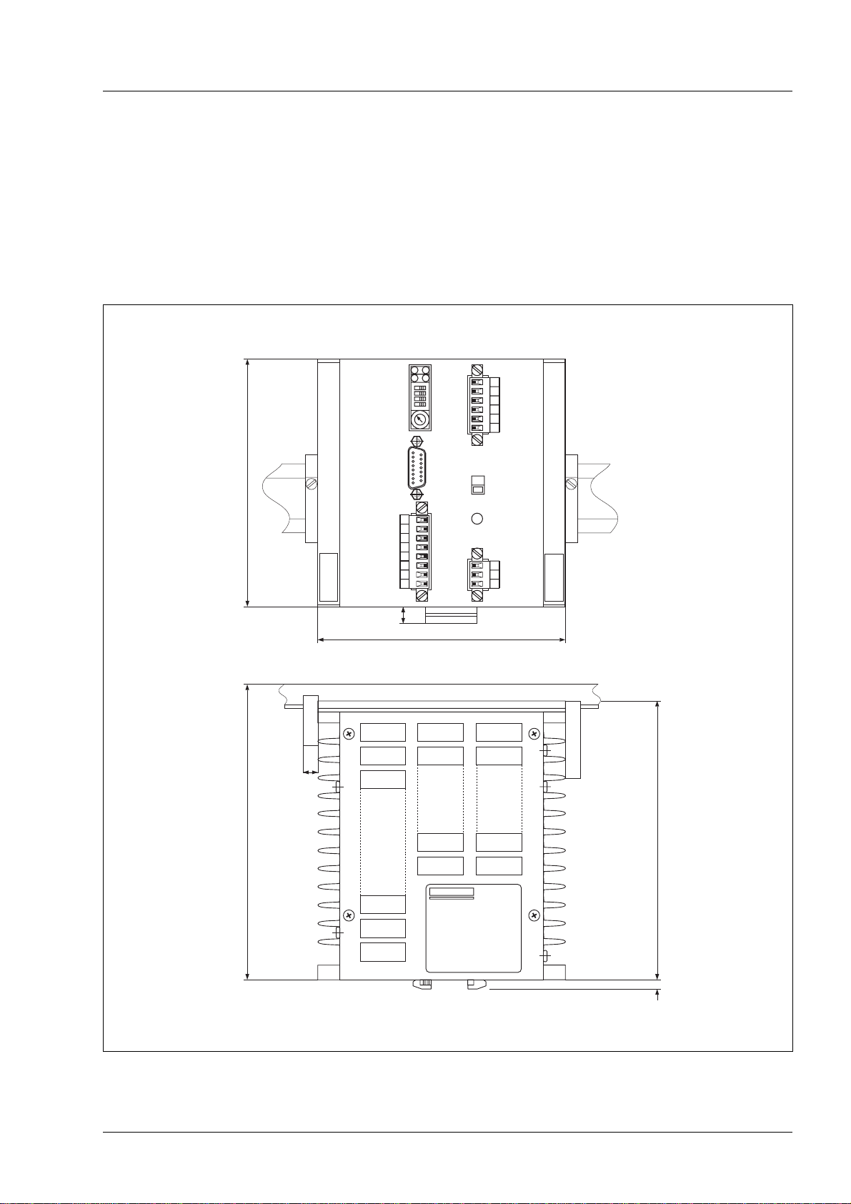
1.4.2 Mechanical data
Dimensions (L x W x H) 135 x 135 x 157 mm
Weight 2.8 kg
230V
135
135
9,5
7,5
157
10
166,5
Figure 1-4 Dimensions of the equipment
General Description
WS5-5 Doc. no. 211.347/DGB 12.92 1 – 5

1.4.3 Ambient conditions
Ambient temperature:
Working 0°C to 50°C
Storage/transportation -25°C to 70°C
Change in ambient temperature:
Working max. 10 K/h
Storage/transportation max. 20 K/h
Humidity class - components F as per DIN 40040
Humidity class tested according to IEC 68 part 2-3
at:
•air temperature +40°C, +2°C
•relative air humidity 93%; +2%-3%
Radio shielding with external filter as
per VDE 0871-A
Overvoltage stability as per VDE 0160
Resistance to interference as per
VDE 0843 / IEC 801
Dew formation not permitted
NOTE
When the WS5-5 is mounted in a
switch cabinet, it must be remembered
that the power loss which can be
removed depends on the design of the
cabinet, its ambient temperature and
the arrangement of the equipment.
See section 2.3
General Discription
1 – 6 WS5-5 Doc. no. 211.347/DGB 12.92
2 Installation
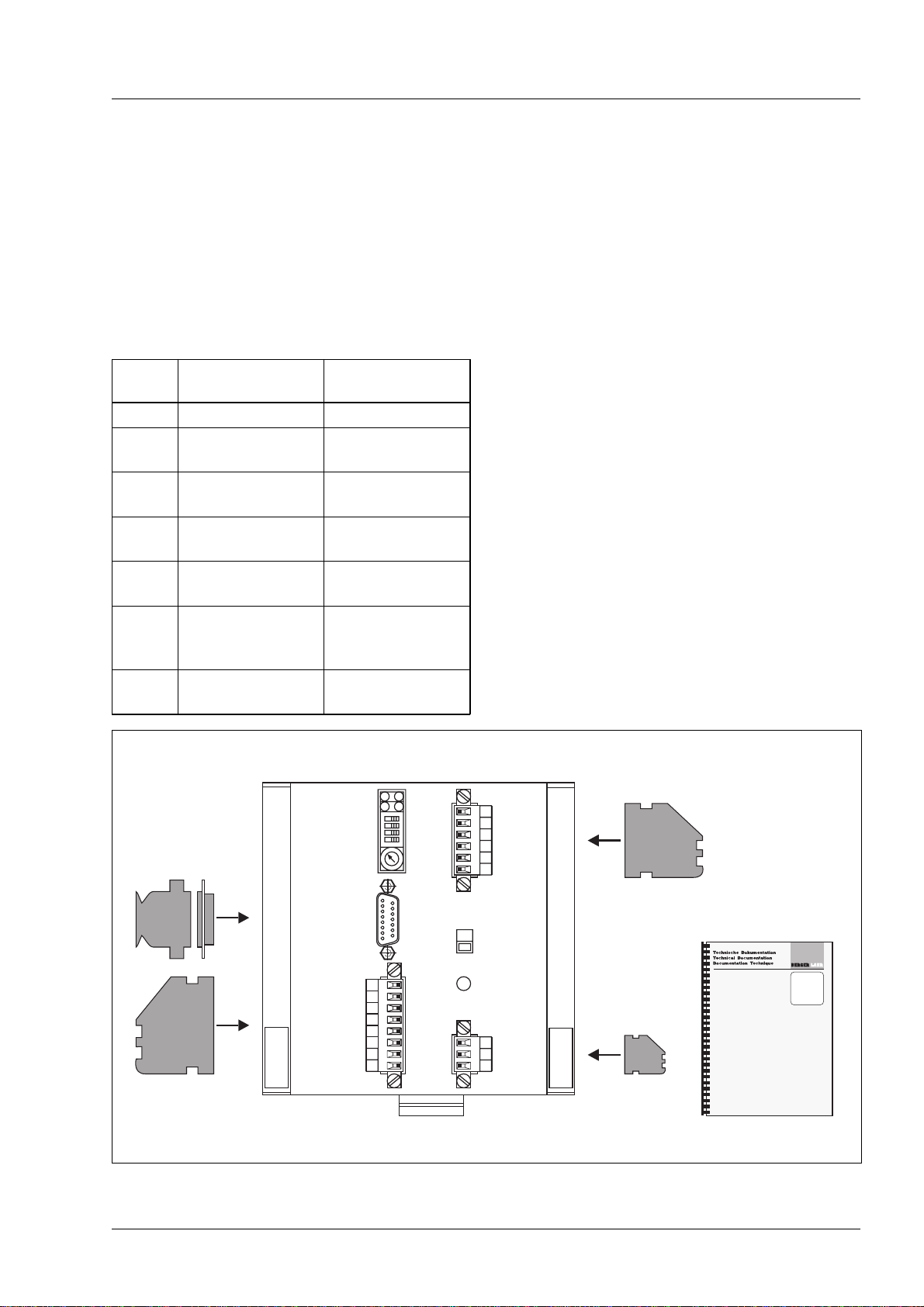
2.1 Parts Specification
The specification must be checked for complete-
ness.
The specification includes (Figure 2-1) comprises:
Q’ty Description Order number
1 WS5-5.281-00 64652810006
1 Plug shell Mains
connection 98050060642
1 Plug shell Motor
connection 98050060600
1 Plug shell for
signal interface 2 98050060642
1 Sub-D socket
(15 pole) 98050060558
1 Housing for
Sub-D socket
(15 pole)
98050060298
1 WS5-5 Technical
documentation Doc. no.
211.347/DGB
230V
WS5-5
Figure 2-1 Parts specification
Installation
WS5-5 Doc. no. 211.347/DGB 03.96 2 – 1
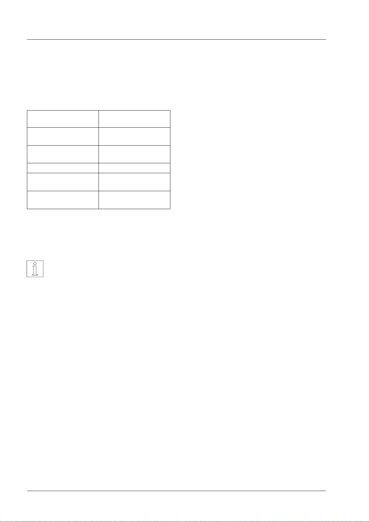
2.2 Accessories
The following accessories can be supplied by
special order:
Description Order number
Signal cable for signal
interface 1 see Appendix
Signal cable for signal
interface 2 see Appendix
Motor cable see Appendix
Stepping motor see catalogue
Doc. no. 350
End bracket EW 35 038356 from Fa.
Weidmüller
The signal cables for signal interface 1 have con-
nectors at both ends and have a length of 1.5 m.
NOTE
For a description of the accessories,
see Appendix 6.2
Installation
2 – 2 WS5-5 Doc. no. 211.347/DGB 03.96

2.3 Mounting
CAUTION
The WS5-5 must be housed in a
switch cabinet so as to ensure resist-
ance to interference and prevent the
equipment from being contaminated.
Make sure that there are adequate pro-
visions for the dissipation of heat!
The equipment is fitted to a supporting rail on the
mounting wall by means of the fasteners at the
back of the equipment and is secured at the sides
by the end brackets. The minimum clearance be-
tween several WS5 units or from other pieces of
equipment must be 10 cm. The outer surfaces of
the equipment act as a heat sink to remove the
heat. The maximum power dissipation of the equip-
ment is 80 W.
2.4 Cabling
2.4.1 General instructions
All the electrical connections will be made by multi-
pole plug connections on the front panel of the
equipment (Figure 2-3). Ready-made cables are
available as accessories (see section 2.2).
DANGER
•Switch off mains voltage before con-
necting cables!
•The power connections (motor,
mains) should be carried out only by
qualified electrical engineers in ac-
cordance with VDE 0105!
CAUTION
•Make sure that the cables are
screened and fitted with strain-relief
clamps!
•Twist every pair of signalling cables
before connecting them!
•Lay mains, motor and signal cables
so that there is a space between
them!
230V
Motor
connection
Mains
connection
Signal
interface1
Signal
interface2
Figure 2-3 Overview of connections
T
am
=ambienttemperature
I
phase
=phasecurrent
T
am
[˚C]
Forcedcooling≥1m/s
Convectioncooling
I
phase
[A]
50
25
1,6 2,8
Figure 2-2 Cooling
Installation
WS5-5 Doc. no. 211.347/DGB 03.96 2 – 3

2.4.2 Connection of the motor
1. Prepare the 5 wires of the motor cable and the
screen which are to be connected to the plug
end with boot lace ferrules.
2. Insert the 6 wires into cap of the mating plug as
shown in Figure 2-4 and tighten the screws.
3. Join the two plug shell halves together.
4. Set the plug to connection 09 and tighten screws.
CAUTION
•To minimise the losses in the cable
and the power drive, it is advisable
to have as short a cable route as
possible.
•The maximum length of the motor
cable is 50 m.
•For cable diameter, see technical
data.
DANGER
The locking mechanism of the motor
plug may only be opened when the
mains voltage has been disconnected.
Circuitry of the motor
The circuitry of the motor uses a pentagram connec-
tion, see Figure 2-5.
NOTE
In the pentagram circuit twice the
phase current flows in the motor con-
necting wires.
A1
A2
A3
A4
A5
A6
Phase1
Phase2
Phase3
Phase4
Phase5
Screen(PE)
yellow
blue
orange
grey
brown
09
Figure 2-4 Motor connection
W4
W4
W5
W5
W1
W1
W3
W3
W2
W2
5
4
3
2
1
6
BN
GY
OG
BU
YE
BU
BU
RD
RD
OG
OG
GN
GN
GY
GY
BK
BK
BN
BN
VI
VI
YE
YE
WH
WH
.
.
.
.
.
WH
YE
VI
BN
BK
GY
GN
OG
RD
BU
=
=
=
=
=
=
=
=
=
=
white
yellow
violet
brown
black
grey
green
orange
red
blue
0
3
2
1
45678
9
Figure 2-5 Circuitry of the motor
Installation
2 – 4 WS5-5 Doc. no. 211.347/DGB 03.96

2.4.3 Adjustment of the equipment to mains
voltage
The equipment can be adjusted to mains voltages
115 V AC or 230 V AC.
1. Disconnect mains voltage to the WS5-5.
2. Using a screw driver, for example, turn voltage
switch 10 into the desired position:
switch at top: 115 V AC
switch at bottom: 230 V AC.
The position which has been set is indicated on the
switch.
CAUTION
The mains voltage must always be
turned off before any alteration is
made to the position of the voltage
switch.
2.4.4 Connecting of the mains cable
1. Prepare the wires of the mains by fitting boot lace
ferrules at the plug end.
2. Insert the 3 wires into mating plug terminal block
as shown in Figure 2-7 and tighten screws.
3. Join the plug shell halves together.
4. Set the plug to connection 12 and tighten screws.
DANGER
Make sure that the mains voltage is
disconnected before loosening the
mains cable!
230V
10
11
VoltageSwitch
LEDLineOn
Figure 2-6 Adjustment of the mains voltage
L
N
Mains
Protectiveconductor
(PE)
12
Figure 2-7 Mains connection
Installation
WS5-5 Doc. no. 211.347/DGB 03.96 2 – 5
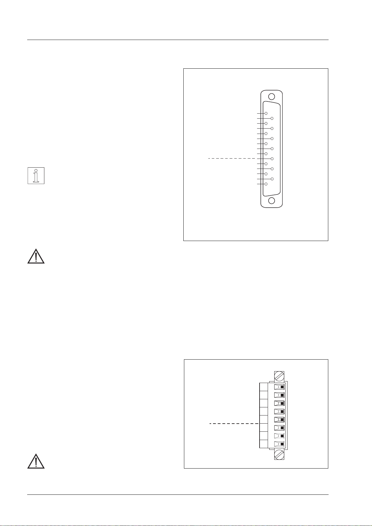
2.4.5 Connection of the signal cables
Signal cable of signal interface 1
1. Twist the wires of the signal cable for signal
interface 1 in pairs and solder to the terminals of
the 15-pole sub-D socket connector strip as
shown in Figure 2-8.
2. Insert cable underneath the strain relief clamp
and secure. Connect screen to earth (GND) on
control side.
NOTE
When using a push-pull drive, it may
be useful to connect the screen to the
plug shell on both ends of the cable.
3. Fit socket shell.
4. Plug socket to socket connector strip 07, and
screw tight.
CAUTION
•For maximum cable length to signal
interface 1, see standard for RS 422
interfaces.
•All signal connections must be safely
isolated from the mains.
•The earth (GND) of signal interfaces
1 and 2 is connected internally to the
protective conductor.
•It is not permitted to apply a voltage
between earth (GND) and protective
conductor in order to avoid damage.
Signal cable of signal interface 2
1. Prepare the 8 wires of the signal cable for signal
interface 2 and fit to plug with boot lace ferrules.
2. Insert the wires into mating plug terminal block as
shown in Figure 2-9 and screw tight.
3. Join the plug shell halves together.
4. Fit plug to terminal 08 and screw tight.
CAUTION
•Maximum length of signal cable:
50 m.
1
2
3
4
5
6
7
8
9
10
11
12
13
14
15
PULSE
PULSE
DIRECTION
DIRECTION
ENABLE
ENABLE
PWM/BOOST
PWM/BOOST
GND
READY
READY
GND
READY*
+
-
+
-
+
-
+
-
+
-
07
OPENCOLLECTORoutput(npn)
I
max
=10mA
U
CEsat
≤1.2V
(short-circuit-proofupto6V)
*
InputsOutputs
Figure 2-8 Connector pin assignment for signal
interface 1
8
7
6
5
4
3
2
1
GND
READY
READY
ZEROPHASE
ZEROPHASE
PWM/BOOST
GATE
ENABLE
-
+
-
+
08
OutputsInputs
Figure 2-9 Connector pin assignment for signal
interface 2
Installation
2 – 6 WS5-5 Doc. no. 211.347/DGB 03.96

2.4.6 Wiring of the signal interfaces
The WS5-5 is activated by an external controller via
signal interface 1 and/or 2.
The two interfaces differ with respect to their pin as-
signments (see Figures 2-8 and 2-9) and the inter-
nal input connections with the signal levels (see
Figures 2-10 and 2- 12).
Signal interface 1
The input signal level of signal interface 1 corre-
sponds to the RS 422 standard value (see section
1.4.1.3). The drive may be achieved, for example,
by a Siemens PLC IP 247 or IP 267 stored-program
controller.
NOTE
Because of the high-impedance
RS 422 interface inputs, up to 10 units
can be connected in parallel on the
input side.
CAUTION
If an input of the RS 422 interface is
not used, the +input of the appropriate
signal can be connected to earth
(GND) in order to ensure resistance to
interference.
NOTE
The inputs of the RS 422 interface
may also be driven via open-collector
outputs; for the possible connections,
see Figure 2-11. The resistance to in-
terference depends on the respective
circuit configuration; the line length as
specified in the RS 422 standard is not
usually reached.
Signal+
Signal-
Signal+*
Signal-*
Signal-*
Signal+*
Signal-
Signal+
GND
R**
R**
R**
R**
GND
GND
GND
Plusswitching
non-inverting
Plusswitching
inverting
Minusswitching
non-inverting
Minusswitching
inverting
10-30V
10-30V
10-30V
10-30V
Becauseofinternalwiring,openinputsassumealevelof5V.
R=2.4kΩfor24Vsupplyvoltage
*
**
Installation
WS5-5 Doc. no. 211.347/DGB 03.96 2 – 7
++
+
U
S
U 33V
I
L
=10mA
100Ω
1, 2, 3, 4
9, 10, 11, 12
8
15
+ 5 V
U
S high
=0,1Và30V
U
S low
=-0,1Và-30V
R
i
≥10kΩ
Inputs
Outputs
Figure 2-10 Internal wiring of signal interface 1

Signal interface 2
The input level of signal interface 2 corresponds to
the PLC standard. The drive may be provided by
any commercial PLC.
NOTE
The outputs +READY (pin 6) and
-READY (pin 14) of signal interface 1
are connected in parallel to +READY
(pin 6) and -READY (pin 7) of inter-
face 2.
+
U
S
+
U33V 2kΩ
1, 2, 3
4, 6
5, 7
8
U
S low
=0Vto3V
U
S high
=13Vto0V
R
i
≥4,7kΩ
I
L
=0,4mAto25mA
Inputs
Outputs
Figure 2-12 Internal wiring of signal interface 2
Installation
2 – 8 WS5-5 Doc. no. 211.347/DGB 03.96
This manual suits for next models
2
Table of contents
Popular DC Drive manuals by other brands

Nord Drivesystems
Nord Drivesystems SK 180E Series manual

SEW-Eurodrive
SEW-Eurodrive MOVIMOT MM D Series operating instructions

Aerotech
Aerotech MPS50SV Hardware manual

SEW-Eurodrive
SEW-Eurodrive MOVITRAC LTP-B operating instructions

BMG
BMG CRUSADER ONE 72H-033 instruction manual

AVL
AVL Compu-Dobby 5 quick reference


ABB
ABB ACS880 Series Supplement

KB Electronics
KB Electronics Penta Power KBRG-255 Installation and operating instructions

Danfoss
Danfoss MCB 113 operating guide

Toshiba
Toshiba Tosvert VF-A5 instruction manual

BeiJer
BeiJer BFI-H3 Start-up

Rockwell Automation
Rockwell Automation PowerFlex 755TM Original instructions