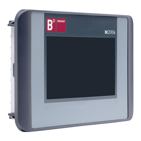
BERGHOF DC1005 Technical Document

ZUNDEL Holding Enterprise
DIALOG
CONTROLLER
DC1005
DC1010
DC1012
V.1.3
Equipment Manual

Copyright © BERGHOF Automationstechnik GmbH
Reproduction and duplication of this document and utilization and communication of its content are
prohibited, unless with our express permission.
All rights reserved. Damages will be payable in case of infringement.
Disclaimer
The content of this publication was checked for compliance with the hardware and software described.
However, discrepancies may arise, therefore no liability is assumed regarding complete compliance.
The information in this document will be checked regularly and all necessary corrections will be included
in subsequent editions. Suggestions for improvements are always welcome.
Subject to technical changes.
Trademark
CANtrol®// and Are registered trademarks of BERGHOF Automationstechnik GmbH
Legal Notice
For the proper characterization of our products it is essential that we employ registered trademarks and
manufacturer names in the documentation related to the services and goods we sell. We would ex-
pressly note that all trademarks, brand names and marks as well as manufacturer names used in this
document are the sole property of the individual owner and are used by us strictly for the purposes of
characterizing our product.
General Information on this Manual
Content:
This manual describes the DIALOG CONTROLLER DC1005 and its modifications. The product-related
information contained herein was up to date at the time of publication of this manual.
Completeness:
This manual is complete only in conjunction with the user manual entitled
'Introduction
to CANtrol Automation System’
s and the product-related hardware or software user manuals required for the particular application.
Standards:
The CANtrol automation system, its modules and its application are all oriented towards the interna-
tional standard, IEC 61131, Part 1 to 4 (EN 61131, Part 1 to 3 and Bbl 1).
Supplementary Sheet 1 of EN 61131 (IEC 61131-4) entitled ‘User Guidelines’ is of particular importance
for the user.
Order numbers:
Please see the relevant product overview in the ‘Introduction to CANtrol Automation System’ manual for
a list of available products and their order numbers.
ID No.: 2809820
You can reach us at:
BERGHOF Automationstechnik GmbH
Harretstrasse 1
72800 Eningen / Germany
Phone: +49 7121 / 894-0
Fax: +49 7121 / 894-100
www.berghof-automation.de
BERGHOF Automationstechnik GmbH works in accordance with DIN EN ISO 9001:2000

BERGHOF Automation DIALOG CONTROLLER
DC1000_HB_en_2D0982003ZD00.doc 3
Update
Version Date Subject
1.1 22.09.06 First version
1.2 Inexistent
1.3 31.05.07 Dimensions updated under “Technical Specifications” and in the graphs.
Plug/unplug cycles added to the “USB Pin Assignment” section of the technical
specifications. Description, “Chemical Resistance for Touch Screens” and "I/O-
Modules" included.
Notice to 'SD-card reader' included. Update under 'Power Supply -Internal
power pack, 'Profibus master card' and 'Profibus slave card'.

DIALOG CONTROLLER BERGHOF Automation
4 DC1000_HB_en_2D0982003ZD00.doc
This page intentionally blank.

BERGHOF Automation DIALOG CONTROLLER
DC1000_HB_en_2D0982003ZD00.doc 5
Contents
1. GENERAL INFORMATION ........................................................................................9
1.1. About This Manual.................................................................................................................................9
1.2. Hazard Categories and Terminology..................................................................................................10
1.3. Qualified Personnel..............................................................................................................................11
1.4. Due Diligence........................................................................................................................................11
1.5. Basic Safety Measures ........................................................................................................................12
1.6. Use as Prescribed................................................................................................................................13
1.7. Conformity Declaration .......................................................................................................................13
1.7.1. CE Notice (European Union) ...................................................................................................13
1.8. Transport and Setup............................................................................................................................14
2. PRODUCT DESCRIPTION.......................................................................................15
2.1. Identification.........................................................................................................................................17
2.2. DIALOG CONTROLLER DC1005 / DC1010 / DC1012 Construction.................................................18
2.2.1. Block Circuit Diagram ..............................................................................................................18
2.3. Technical Specifications, DC1005......................................................................................................19
2.3.1. DC1005 Front View .................................................................................................................21
2.3.2. DC1005 Rear View ..................................................................................................................21
2.3.3. DC1005 Dimensions................................................................................................................22
2.3.4. DC1005 Panel Cutout..............................................................................................................23
2.4. Technical Specifications, DC1010......................................................................................................24
2.4.1. DC1010 Front View .................................................................................................................26
2.4.2. DC1010 Rear View ..................................................................................................................26
2.4.3. DC1010 Dimensions................................................................................................................27
2.4.4. DC1010 Panel Cutout..............................................................................................................27
2.5. Technical Specifications, DC1012......................................................................................................28
2.5.1. DC1012 Front View .................................................................................................................30
2.5.2. DC1012 Rear View ..................................................................................................................30
2.5.3. DC1012 Dimensions................................................................................................................31
2.5.4. DC1012 Panel Cutout..............................................................................................................31
2.6. Mounting and Connection...................................................................................................................32
2.6.1. Mounting ..................................................................................................................................32
2.6.2. Connections.............................................................................................................................32
2.7. Pin Assignment....................................................................................................................................33
2.7.1. Pin Overview............................................................................................................................33
2.7.2. Power Supply...........................................................................................................................33
2.7.3. 10/100 Base T Network Connection (Ethernet).......................................................................33
2.7.4. USB..........................................................................................................................................34
2.7.5. CAN Bus ..................................................................................................................................35
2.7.6. Serial Ports ..............................................................................................................................36

DIALOG CONTROLLER BERGHOF Automation
6 DC1000_HB_en_2D0982003ZD00.doc
2.7.7. E-Bus....................................................................................................................................... 37
2.7.8. Connections for Expansion Ports............................................................................................ 37
2.8. SD-Card ................................................................................................................................................ 38
3. DIALOG CONTROLLER OPERATION.....................................................................39
3.1. Commissioning.................................................................................................................................... 39
3.2. Function Selection, Indicators, Diagnostics.....................................................................................39
3.2.1. Status Indicators ..................................................................................................................... 39
3.3. Service Menu ....................................................................................................................................... 41
3.3.1. Using the Service Menu..........................................................................................................42
3.3.2. Parameter Window.................................................................................................................. 43
“IP Config” service menu......................................................................................................... 43
“PLC” service menu ................................................................................................................ 46
“INFO” service menu............................................................................................................... 47
“Display” service menu............................................................................................................ 48
3.3.3. PLC Window ........................................................................................................................... 49
3.4. Decommissioning................................................................................................................................ 50
3.4.1. Disposal .................................................................................................................................. 50
3.5. Maintenance......................................................................................................................................... 50
3.6. Help in Case of Problems................................................................................................................... 50
4. CHEMICAL RESISTANCE........................................................................................51
4.1. Resistance of the Touch Screen........................................................................................................ 51
4.2. Resistance of the Front Foil Sheeting to Chemicals ....................................................................... 52
4.2.1. General Resistance of the Foil Sheeting Material .................................................................. 52
4.2.2. Resistance to Household Chemicals ...................................................................................... 53
4.2.3. Environmental Values ............................................................................................................. 53
Lowest exposure temperature................................................................................................. 53
Highest exposure temperature................................................................................................ 53
Outdoor use............................................................................................................................. 53
5. EXTENSION MODULES...........................................................................................55
5.1. I/O Card With SC-CAN Interface......................................................................................................... 56
5.1.1. Technical Specifications.......................................................................................................... 57
5.1.2. Pin assignment........................................................................................................................ 58
Pin overview............................................................................................................................ 58
Power supply........................................................................................................................... 58
Installation ............................................................................................................................... 59
CAN Bus for contact line communications.............................................................................. 60
External 7-segment display..................................................................................................... 61
5.1.3. Analog Inputs .......................................................................................................................... 62
5.1.4. Digital Inputs/Outputs 12/4/8-0.5 ............................................................................................ 63
Digital inputs, positive switched .............................................................................................. 64
Basic input circuit diagram ...................................................................................................... 64
Digital input data ..................................................................................................................... 65

BERGHOF Automation DIALOG CONTROLLER
DC1000_HB_en_2D0982003ZD00.doc 7
Digital input operating ranges ..................................................................................................66
5.1.5. Digital Outputs, Positive Switched...........................................................................................67
Basic output circuit diagram.....................................................................................................67
Digital output data....................................................................................................................68
Digital output overload behavior ..............................................................................................69
5.1.6. Digital Input/Output Pin Assignments ......................................................................................70
Encoder interface.....................................................................................................................70
5.2. PROFIBUS MASTER Card ...................................................................................................................71
5.2.1. Technical Specifications ..........................................................................................................72
5.2.2. Front View and Pin Assignment...............................................................................................73
Pin overview.............................................................................................................................73
Power supply ...........................................................................................................................73
Installation................................................................................................................................73
PROFIBUS MASTER interface................................................................................................74
5.3. PROFIBUS SLAVE Card ......................................................................................................................76
5.3.1. Technical Specifications ..........................................................................................................77
5.3.2. Front View and Pin Assignment...............................................................................................78
Pin overview.............................................................................................................................78
Power supply ...........................................................................................................................78
Installation................................................................................................................................78
PROFIBUS SLAVE interface ...................................................................................................79
6. MAINTENANCE........................................................................................................81
6.1. Real-Time Clock with Backup Battery................................................................................................82
6.1.1. Battery Replacement ...............................................................................................................83
7. ANNEX .....................................................................................................................85
7.1. Environmental Protection ...................................................................................................................85
7.1.1. Emission ..................................................................................................................................85
7.1.2. Disposal ...................................................................................................................................85
7.2. Maintenance/Upkeep............................................................................................................................85
7.3. Repairs/Service ....................................................................................................................................85
7.3.1. Warranty ..................................................................................................................................85
7.4. Nameplate.............................................................................................................................................86
7.5. Addresses and Bibliography ..............................................................................................................88
7.5.1. Addresses................................................................................................................................88
7.5.2. Standards/Bibliography............................................................................................................88

DIALOG CONTROLLER BERGHOF Automation
8 DC1000_HB_en_2D0982003ZD00.doc
This page intentionally blank.

BERGHOF Automation General
2VF100106FE00.doc DC1000_HB_en_2D0982003ZD00.doc 9
1. General Information
Documentation This equipment manual is intended for qualified personnel and contains information
regarding the mounting, installation, commissioning and maintenance of the
DIALOG CONTROLLER.
The information contained in this manual is subject to change without prior notice.
1.1. About This Manual
This equipment manual is an integral part of the product. Make sure the equipment
manual is always available near the product’s point-of-employment. The manual
contains information about the following topics:
• Areas of application;
• Safety;
• Mechanical construction;
• Electrical construction;
• Connections;
• Commissioning;
• Care and maintenance;
• Decommissioning;
• Disposal.

General BERGHOF Automation
10 DC1000_HB_en_2D0982003ZD00.doc 2VF100106FE00.doc
1.2. Hazard Categories and Terminology
Immediate danger
Failure to observe the information indicated by this warning will result in death,
serious injury or extensive property damage.
Potential danger
Failure to observe the information indicated by this warning may result in death,
serious injury or extensive property damage.
Danger
Failure to observe the information indicated by this warning may result in injury or
property damage.
No hazard
Information indicated in this manner provides additional notes concerning the
product.

BERGHOF Automation General
2VF100106FE00.doc DC1000_HB_en_2D0982003ZD00.doc 11
1.3. Qualified Personnel
Only qualified personnel may install, operate and maintain the DIALOG
CONTROLLER.
Within the context of this documentation and the safety information it contains,
qualified personnel constitutes trained specialists who have the authority to mount,
install, commission, ground and identify equipment, systems and power circuits in
accordance with the standards of safety technology, and who are familiar with the
safety concepts of automation technology.
1.4. Due Diligence
The operator or original equipment manufacturer (OEM) must ensure:
• That the DIALOG CONTROLLER is only employed for its intended use;
• That the DIALOG CONTROLLER is only employed in a fault-free,
operational state;
• That the equipment manual is always maintained in a complete and
legible condition and is available at the point-of-employment of the
DIALOG CONTROLLER;
• That only properly qualified and authorized personnel mount, install,
commission and maintain the DIALOG CONTROLLER;
• That these specialists receive regular and ongoing instruction in all pertinent
questions related to work safety and environmental protection and that they
are familiar with the contents of the equipment manual, in particular, with the
safety information it contains;
• That the equipment identifiers as well as safety and warning information ap-
plied to the DIALOG CONTROLLER are not removed and that they are main-
tained in a legible condition;
• That all international, federal, state and local ordinances governing the
control of machinery and equipment applicable at the location at which the
DIALOG CONTROLLER is employed are complied with;
• That the users always have available all relevant information they require
with regard to the DIALOG CONTROLLER and its employment.

General BERGHOF Automation
12 DC1000_HB_en_2D0982003ZD00.doc 2VF100106FE00.doc
1.5. Basic Safety Measures
Working on the DC Before beginning work on the DIALOG CONTROLLER you must always;
• First ensure that the equipment is in a safe state;
• Then first switch the DC off, followed by the equipment, and;
• Only then disconnect the DC from the equipment.
HAZARDOUS
PROCESSES
Hazards due to unforeseeable functional and processing movements when
the INDUSTRIAL-PC is disconnected.
These can result in death, serious injury or extensive property damage.
All equipment components must be disconnected from the DIALOG
CONTROLLER whenever the DIALOG CONTROLLER is not being used for op-
erational or control purposes, e.g., during maintenance or during functional
checks after repairs.
Lock out and tag out all equipment components after they have been
switched off!
Opening the DC First, please note all the tasks steps outlined in the above section “Working on the
DC”.
The supply voltage must be switched off before opening the housing or when com-
ponents are being installed or removed.
To do this, switch the power supply to the DIALOG CONTROLLER off. Then re-
move the plug from the power supply socket on the DIALOG CONTROLLER.
HAZARDOUS
VOLTAGE
Do not open the housing cover with the power switched on!
Hazard due to contact with live components.
This can result in death, serious injury or extensive property damage.
Only open the housing cover once the DIALOG CONTROLLER has been safely
disconnected from the power supply.

BERGHOF Automation General
2VF100106FE00.doc DC1000_HB_en_2D0982003ZD00.doc 13
1.6. Use as Prescribed
This is a modular automation system based on the CANbus, intended for industrial
control applications within the medium to high performance range.
The automation system is designed for use within Overvoltage Category I
(IEC 364-4-443) for the controlling and regulating of machinery and industrial
processes in low-voltage installations in which the rated supply voltage does not
exceed 1,000 VAC (50/60 Hz) or 1,500 VDC.
Qualified project planning and design, proper transport, storage, installation, use
and careful maintenance are essential to the flawless and safe operation of the
automation system.
The automation system may only be used within the scope of the data and applica-
tions specified in the present documentation and associated user manuals.
The automation system is to be used only as follows:
• as prescribed,
• in technically flawless condition,
• without arbitrary or unauthorized changes and
• exclusively by qualified users
The regulations of the German professional and trade associations, the German
technical supervisory board (TÜV), the VDE (Association of German electricians)
or other corresponding national bodies are to be observed.
Safety-oriented (fail-safe) systems
Particular measures are required in connection with the use of SPC in safety-
oriented systems. If an SPC is to be used in a safety-oriented system, the user
ought to seek the full advice of the SPC manufacturer in addition to observing any
standards or guidelines on safety installations which may be available.
As with any electronic control system, the failure of particular components may
result in uncontrolled and/or unpredictable operation.
All types of failure and the associated fuse systems are to be taken into account
at system level. The advice of the SPC manufacturer should be sought if neces-
sary.
1.7. Conformity Declaration
1.7.1. CE Notice (European Union)
• The DIALOG CONTROLLER is currently still being tested.
Our goal is to obtain CE certification for operating the device in both industrial
as well as domestic environments.

General BERGHOF Automation
14 DC1000_HB_en_2D0982003ZD00.doc 2VF100106FE00.doc
1.8. Transport and Setup
Please note the specified storage conditions in the Section, “Technical Specifica-
tions”.
Transport Protect the DIALOG CONTROLLER against extreme mechanical stress during
transport. Always transport the DIALOG CONTROLLER in its original packaging.
The built-in components are extremely sensitive to jarring and strong vibrations.
CONDENSATION
Condensation hazard resulting from climatic fluctuations.
Risk of damage as a result of moisture forming on or in the DIALOG
CONTROLLER (condensation). This can result in destruction of the device or
consequential damages.
After storage or transport in cold weather or under conditions of strongly fluctuat-
ing temperatures, the DIALOG CONTROLLER must be allowed to slowly adjust
to the ambient temperature at its point of use before it can be taken into service.
In case of condensation, the unit may not be taken into service for at least
12 hours (temperature compensation).
Unpacking Proceed as follows:
• Inspect the packaging for any external damage.
If the packaging is severely damaged or if damage to the contents
can be detected, do not open the packaging any further.
Immediately contact your shipper and your supplier.
• Remove the packaging. Do not discard the original packaging!
The packaging can be used for subsequent transport.
• Inspect the contents for visible shipping damage.
• Check the contents against the order for completeness.
Save all included documentation. This documentation contains
important information concerning the DIALOG CONTROLLER and is
an integral part of the product.
• If shipping damage is detected or if the received contents do not
agree with the order, please contact your supplier immediately.
Setup This DIALOG CONTROLLER is designed for installation in fully enclosed circuit
cabinets of industrial machinery and equipment.
When installing the DIALOG CONTROLLER, take particular care to ensure that the
included seal profiles are not damaged. Also ensure compliance with the ambient
conditions specified under “Technical Specifications”.

BERGHOF Automation Product Description
2VF100107FE03.doc DC1000_HB_en_2D0982003ZD00.doc 15
2. Product Description
Short description The DIALOG CONTROLLER is a real-time control module with a display and a
broad spectrum of data interfaces. The module can be programmed in 'C' or in
accordance with IEC 61131-3 (CoDeSys 2.3).
Installation The DIALOG CONTROLLERs are intended for front panel or switch cabinet instal-
lation in harsh industrial environments. Maintenance is minimal, thanks to their fan-
free design and flash memory.
Processors The DIALOG CONTROLLER is equipped with either a 266 MHz or 400 MHz
POWERPCTM processor from Freescale.
Display The great differences in the appearance of the DIALOG CONTROLLER is based
on the selection of the employed display technology and a common display diago-
nal size. 5.7” units with a monochrome (STN), color (CSTN) or TFT display are a-
vailable. Above a diagonal screen size of 10.4” only TFT displays are employed.
Unit housing dimensions and protective method (IP65 on the front) do not depend
on whether the version in question has a touch screen or matrix keypad.
Ethernet A 10/100 MBit/s Ethernet interface is included. TCP/IP and UDP/IP protocols offer
highly flexible connections to visualization software, higher order control units or an
IT infrastructure.
USB ports The two USB host ports provide interfaces for widely dispersed peripheral devices.
For example, one USB stick can be used to quickly and easily perform application
updates or data extraction. Please contact our Technical Support if no driver sup-
port is available for a specific USB device.
CAN ports The DIALOG CONTROLLER is equipped with two standard CAN interfaces, both
of which can be operated at 1 MBit/s.
Serial ports A total of three serial ports can be used on the DIALOG CONTROLLER. The
RS232 programming interface is supplemented by an additional RS232 and an
RS485 port.

Product Description BERGHOF Automation
16 DC1000_HB_en_2D0982003ZD00.doc 2VF100107FE03.doc
E-bus extension The DIALOG CONTROLLER’s I/O level can be expanded via the E-bus socket to
include up to seven E-bus subscribers.
Expansion slots The device is equipped with three expansion slots for expansion cards (e.g., I/O
cards) with the associated SPI interface. Alternately, one of the slots can be used
for an “Anybus®” embedded bus module (e.g., Profibus DP) manufactured by
HMS.
Real-time clock A software interface can be used to set or reset a real-time clock equipped with a
backup battery.
SD card reader Data can be written to or read from memory cards using the conventional MMC/SD
card interfaces.
If the SD card reader is activated, then the second RS232 interface (X5) is not
longer available.
Performance feature overview
• Freescale POWERPCTM CPU: 266 (400) MHz
• Application program and data memory(RAM):
64 (128) MB onboard / 32 (96) MB for the application
• Application program memory (Flash):
16 (32) MB onboard / 8 (24) MB for the application
• Retain memory: 16 KB
• 1 Ethernet 10/100 port
• 2 (3) USB host ports
• 2 CAN ports
• 1 RS232 serial port for programming tools and applications
• 2 serial data ports: RS232 / RS485
• I/O level locally expandable via an internal E-bus for up to seven subscribers
(digital / analog)
• 3 onboard expansion slots for I/Os and a bus module
• Real-time clock
• MMC /SD card slot
Standard delivery The controller module’s standard delivery includes:
• DIALOG CONTROLLER DC1000.

BERGHOF Automation Product Description
2VF100107FE03.doc DC1000_HB_en_2D0982003ZD00.doc 17
2.1. Identification
Product DIALOG CONTROLLER
Type DC10xx
Identification key The identification code provides a key to the DIALOG CONTROLLER (refer to the
nameplate). The code can be read as follows.
2VF100227DG01_en.cdr
Nameplate
2VF100228DG01_en.cdr
DC1005C T MP 66
1 2 3 4 5 6 7 8 9 10 11 12 13 14 15 16
...
05
10
12
15
=
= 10,4”
= 12,1”
= 5,0”1
5,7”
M
=
= Color (CSTN)
= Color TFT
C
T
Monochrome (STN)
T
K
= Touchpanel
= Keyboard
MP266
MP400
= Power PC 266 MHz
= Power PC 400 MHz
Screen size
(diagonal)
Activation method
Processor type
Manufacturer’s production date code

Product Description BERGHOF Automation
18 DC1000_HB_en_2D0982003ZD00.doc 2VF100107FE03.doc
2.2. DIALOG CONTROLLER DC1005 / DC1010 / DC1012 Construction
2.2.1. Block Circuit Diagram
2VF100233DG00_en.cdr
FRONT
Front USB
Inverter
Display
Touch /
Keyboard
Display
Unit
X2
X1
X8
X7
X4
X5
X6
X3
+24 V
CPU
Grafik CAN
SIO
Flash
RAM
USB
X
9
BASIS
Controller

BERGHOF Automation Product Description
2VF100107FE03.doc DC1000_HB_en_2D0982003ZD00.doc 19
2.3. Technical Specifications, DC1005
DIALOG CONTROLLER
Product identification
Display type: Input: Designation: Part no.:
Monochrome (STN) Keyboard DC1005M K MP266 270000100
Monochrome (STN) Touchpad DC1005M T MP266 270000000
Color (CSTN) Touchpad DC1005C T MP266 270000200
Color TFT Touchpad DC1005T T MP266 270000300
Color TFT Keyboard DC1005T K MP266 270000900
Display
Diagonal measurement 5.7”
Resolution 320 x 240 pixels (1/4 VGA)
Colors Monochrome (STN): 4
Color (CSTN): 256 (8 bits per pixel)
Color TFT 256 (8 bits per pixel)
CPU, application memory
CPU Freescale PowerPC 266 MHz
Program memory (Flash) 16 MB onboard / 8 MB for the application
Program memory and data memory
(RAM)
64 MB onboard / 32 MB for the application
Retain memory 16 KB
Real-time clock Yes
Development environment CP1131 (CoDeSys 2.3)
Dimensions and weight
Dimensions (WxHxD [mm]) 194 x 172 x 52 (+6 mm front panel)
Weight approx. 1.5 kg
Operating conditions
Ambient temperature range 0°C to 50°C
Relative humidity max. 85 %, non-condensing (monochrome: max. 75 %)
Transport, storage
Ambient temperature range -20°C to +70°C
Relative humidity max. 85 %, non-condensing (monochrome: max. 75 %)
Shock resistance
Vibration Sinusoidal (EN 60068-2-6) test: Fc
10 ... 150 Hz, 1 G (operation mode)
Shock resistance 15 G (approx. 150 m/s²); duration: 10 ms; semi-sinusoidal (EN 60068-2-27)
test: Ea
EMC, protection type
Interference emission EN 61000-6-4, industrial environments
Interference resistance EN 61000-6-2, industrial environments
Protection class III
Insulating resistance EN 61131-2; DC 500 V test voltage
Protection type IP20 (front: IP65)

Product Description BERGHOF Automation
20 DC1000_HB_en_2D0982003ZD00.doc 2VF100107FE03.doc
Power supply (24 V power pack)
Supply voltage +24 VDC (-15% / +20%) SELV
max. alternating component: 5%
Current consumption Typically 1.0 A; max. 2.0 A at +24 VDC
Fusing depending on the I/O load, max. 12A
Polarity reversal protection Yes
Potential isolation Yes, between CAN bus and I/Os
Ethernet port
Number / interface type 1x 10/100 Base T
Connection method RJ45
USB ports
Number / interface types 1 x host USB, Rev. 1.1 (on rear)
1 x host USB, Rev. 1.1 (on front)
Plug/unplug cycles max. 1000
CAN bus ports
Number / interface types 2x standard CAN ISO 11898
Potential isolation CAN0 (X6) potential isolated
Transmission rate max. 1 MBit/s
Terminating resistor Switchable
Serial port
Number / interface types 2x RS232
1x RS485
Potential isolation RS485 (X8) potential isolated
Terminating resistor Switchable with the RS485
E-bus port
Interface types I/O expansion bus for up to 7 E-bus subscribers
Expansion slots
Number / interface types 3 slots for 3 I/O modules
or
2 I/O modules and one AnyBus®module
This manual suits for next models
2
Table of contents
Other BERGHOF Controllers manuals
Popular Controllers manuals by other brands

Fubag
Fubag MICRO 40/12 Operator's manual

Watts
Watts 009 Series INSTRUCTION, INSTALLATION, MAINTENANCE AND REPAIR MANUAL

MULTISPAN
MULTISPAN PIC-4202 operating manual

Aprilaire
Aprilaire 6404 Safety & installation instructions

LAE
LAE AR2-27 Instructions for use

Aerotech
Aerotech Automation1 SI4-2P1 Hardware manual