Bergstrom Dual Zone Front HVAC User manual

2390 Blackhawk Road ●P.O. Box 6007 ●Rockford, IL 61125 ●www.bergstrom.com ●1-866-204-8570
Recreational Vehicle
Dual Zone Front HVAC
Service Manual
Updated: 9/6/2023
Note (Not applicable for hard copies):
1. Phrases in blue are “hyperlinks” that allow user to jump directly to the respective section. Hold
“ctrl” and click the link to use.
2. All section titles are “hyperlinks” allowing the user to jump back to the top of the document.

2
Table of Contents
Page
Service
•Contact Information 5
•Request for Technical Support, Questionnaire 6
•Comments 7
Electrical Systems
•Electrical Schematics 8
•Diagnostic Guide 9
Air Flow Systems
•Basic Description 11
•Main HVAC System Components 12
Component Servicing
•Outdoor HVAC Unit 14
•Indoor HVAC Unit 15
•Freeze Probe 16
•Fresh and Recirculation Air Filters 17
•Actuator(s) 18
•Evaporator Coil 19
•Heater Core 20
•Blower Assembly 21
•Condenser Fan 22
•Condenser Coil 23
•Thermostatic Expansion Valve (TXV) 24
•Other Serviceable Components 25

3
Table of Contents
Air Conditioning System
•Diagnostic Guide 29
•A/C System Operation Check 31
•Expected A/C Performance 32
•Compressor Function Test 33
•Thermostatic Expansion Valve (TXV) Function Test 34
•Refrigerant Charge Information 35
•Service Tips 35
•R134a Temperature/Pressure Chart 36
Dual Zone Front HVAC Owner’s Manual
•Control Panel Operation 38
•Air Distribution 39
•Operating Features 40
•Warranty/Service 41

4
Service
Disclaimer:
WARNING!!
The technical information, provided in this service guide, is intended for use by
properly trained HVAC service personnel, who can ensure a safe and properly
operating system. It is assumed that the user of this guide is trained and experienced
in basic refrigeration principles, in addition to being familiar with Bergstrom HVAC
systems installed on Recreational Vehicles. Technicians who repair or service motor
vehicle A/C systems must be certified by Section 609 (MACS) approved by the EPA.
Before any air conditioning service is started, it is the technician's responsibility to
determine what type of refrigerant is contained in the system. Component marking
and/or service port peculiarities are good places to start to identify the contents.
Bergstrom advises that the usual precautions associated, with servicing a motor
vehicle, be exercised when servicing the HVAC system and assumes no liability
regarding vehicle damage or personal injury. Additionally, Federal and any Local
regulations regarding the handling and use of refrigerants should be always complied
with.
NOTES:
TECHNICAL SUPPORT IS PROVIDED TO CERTIFIED TECHNICIANS ONLY.
BERSTROM DOESN’T SUPPLY TECHNICAL SUPPORT TO RV OWNERS.
THE AIR CONDITIONING SYSTEM CONTAINS REFRIGERANT R134A, UNDER
HIGH PRESSURE, AND SHOULD BE SERVICED BY ONLY QUALIFIED
PERSONNEL.
REPAIRS THAT ALTER THE DESIGN OF THE BERGSTROM SYSTEM, INCLUDING
USE OF NON-BERGSTROM SUPPLIED PARTS, WILL VOID THE WARRANTY AND
ANY BERGSTROM LIABILITY FOR THE HVAC SYSTEM.
THE BERGSTROM HVAC SYSTEM SHOULD BE SERVICED BY A FULLY TRAINED
AND ENVIRONMENTALLY LICENSED TECHNICIAN. FAILURE TO AGREE TO ALL
STATEMENTS COULD RESULT IN SERIOUS INJURIES, FINES AND POSSIBLE
VOIDING OF ANY WARRANTIES.


6
Service
Request for Technical Support Questionnaire
Open the front service door of the coach and verify if you are servicing a
Bergstrom HVAC system by checking the base unit mounted on the front firewall.
Verify customer complaint by operating the vehicle. (Print this page for reference).
DESCRIPTION OF COMPLAINT:
DEALER:
CONTACT/TECH: PHONE #:
CHASSIS: MODEL YR: MODEL:
COACH MANUFACTURER:
CONDENSER TYPE & LOCATION
PRESSURE GAUGE READINGS:
LOW PSIG @ 1500 RPM, HIGH BLOWER SPEED
HIGH PSIG @ 1500 RPM, HIGH BLOWER SPEED
R134A REFRIGERANT CHARGE WEIGHT:
POUNDS
AIR TEMPERATURE & HUMIDITY READINGS:
HUMIDITY LEVEL: %RH
RECIRCULATION INLET AIR TEMPERATURE: ⁰F
DISCHARGE AIR TEMPERATURE (VENT CLOSEST TO BASE UNIT): ⁰F
SUBTRACT THE TWO AIR TEMPERATURES = ⁰F
DIFFERENTIAL


9
Electrical Systems
Diagnostics Guide
Problem
Possible Cause
Corrective Action
Control Panel is not
functional
1. Vehicle ignition switch
isn’t activated.
2. Loss of power supply.
3. Open circuit between
vehicle connection and
control panel.
4. Loose or wrong
connection(s) at the
control panel.
5. Failed control panel.
1. Activate vehicle ignition switch.
2. Examine the chassis’ HVAC
circuit’s protection device for
failure (i.e. fuse or circuit breaker).
3. Check primary connections at
vehicle connection and the control
panel. Verify vehicle voltage at
each connection. Verify ground
connection. Repair or replace
harness if necessary.
4. Ensure all connections are mated
properly. Ensure the harness is
pinned properly in the connector
using the wiring diagram.
5. Replace control panel.
Discharge and/or inlet air
systems are not functioning
properly.
1. Open circuit between
control panel and ECU.
Open circuit between
ECU and actuator.
2. Faulty shutter actuator.
3. Faulty control panel.
4. Faulty ECU.
1. Verify vehicle voltage and ground
at actuator. Perform continuity
test of CAN high and low between
control panel and ECU. Perform
continuity test of actuator signal
between ECU and actuator.
Repair or replace harness if
necessary.
2. Replace the actuator if needed.
Refer to ACTUATOR(S)
3. Replace the control panel if
needed.
4. Replace ECU if necessary.
Blower does not operate at
any speed
1. Open circuit in harness
between the vehicle
connection and blower
connection.
2. Open circuit between
ECU and blower
connection.
3. Faulty ECU
1. Verify vehicle voltage and ground
at vehicle connection and blower
connection. Perform continuity
test between connections. Repair
or replace harness if necessary.
2. Perform continuity test between
ECU and blower connection for
blower speed control. Repair or
replace harness if necessary.
3. Rotate the blower control between
LOW and HIGH speed. Verify
voltage change when speed is
adjusted. Replace ECU if
necessary.

10
Electrical Systems
Problem
Possible Cause
Corrective Action
A/C Clutch does not operate
1. Blower switch is not
activated.
1. Blower must be ON for A/C clutch
to operate.
A/C Clutch does not operate.
Blower is operating properly
1. A/C switch is not
activated.
2. Open circuit between
control head and ECU.
3. Defective A/C freeze
probe.
4. Faulty A/C clutch.
1. Verify A/C switch is depressed
and illuminating correctly.
Replace control panel if
necessary.
2. Perform continuity test of CAN
high and low between control
panel and ECU. Repair or replace
harness if necessary.
3. Perform continuity check for
freeze probe power and ground
between probe and ECU. Replace
harness if no continuity. Replace
probe otherwise.
4. With the engine OFF apply a
separate 12V+ supply directly to
clutch terminals and listen for
clutch engagement. Replace
clutch if there is no engagement.
11
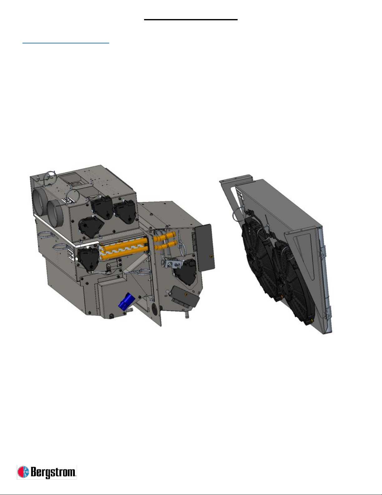
Air Flow Systems
Basic Description
The Bergstrom Dual Zone HVAC System for Jayco consists of four HVAC modules
designed to provide air that has been conditioned to the occupants of the vehicle
cockpit. The driver zone and passenger zone of the panel mode outlets can be
controlled independently for air temperature and blower speed. Two of the HVAC
modules are mounted under the dash, and two under the vehicle hood. The
serviceable components are located within these modules.

13
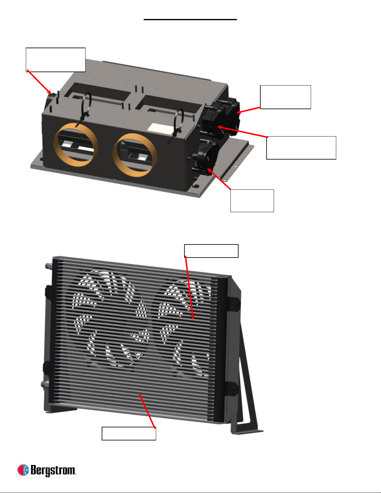
Air Flow Systems
Mode Box
Condenser Assembly
Driver Zone Panel
Mode Actuator
Passenger Zone
Panel Mode Actuator
Defrost Mode
Actuator
Floor Mode
Actuator
Condenser Coil
Condenser Fan

14
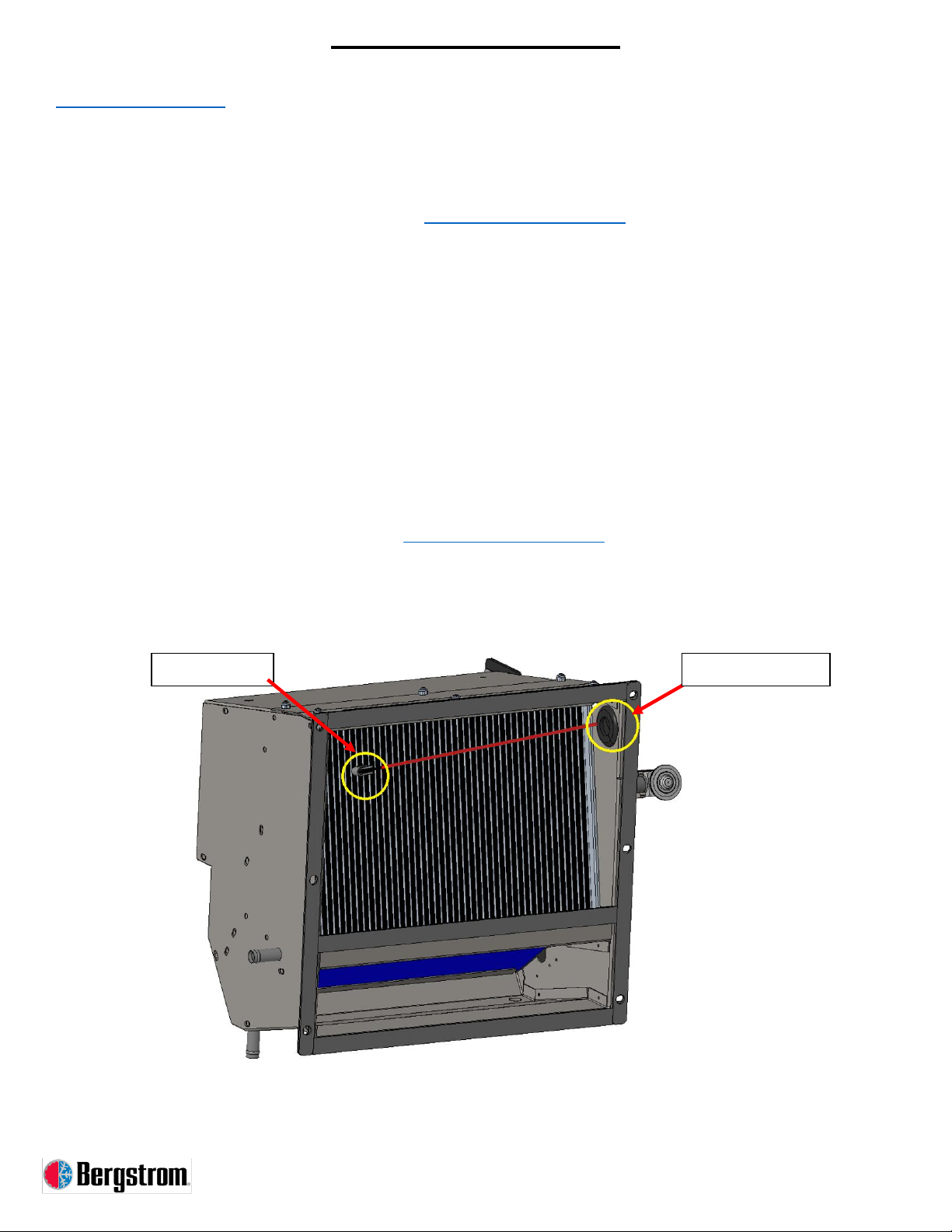
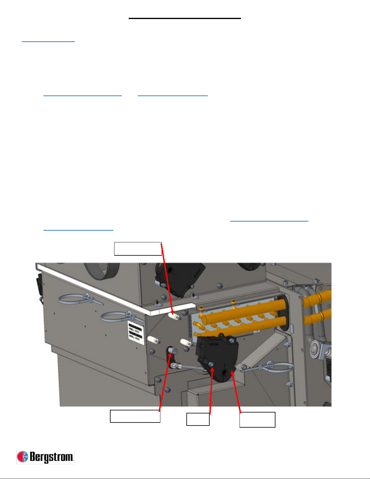
Component Servicing
Outdoor HVAC Unit
Outdoor HVAC Unit Removal
1. Discharge A/C system. Refer to REFRIGERANT CHARGE INFORMATION
2. Remove any hoses/fittings connected to the TXV and the front mounting plate by removing the
1 Allen screw.
3. Disconnect the actuator harness and freeze probe harness.
4. Remove outdoor HVAC unit from the front of the indoor HVAC unit by removing 6 nuts.
Outdoor HVAC Unit Installation
1. Install outdoor HVAC unit to the front HVAC unit with 6 nuts.
2. Connect actuator harness and freeze probe harness.
3. Install hoses/fittings to TXV with front mounting plate and 1 Allen screw (Torque 10 Nm).
4. Charge A/C system. Refer to REFRIGERANT CHARGE INFORMATION
TXV Front
Mounting Plate
TXV
Nut

15
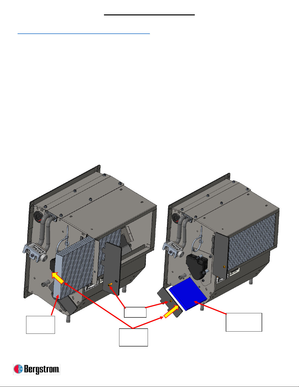
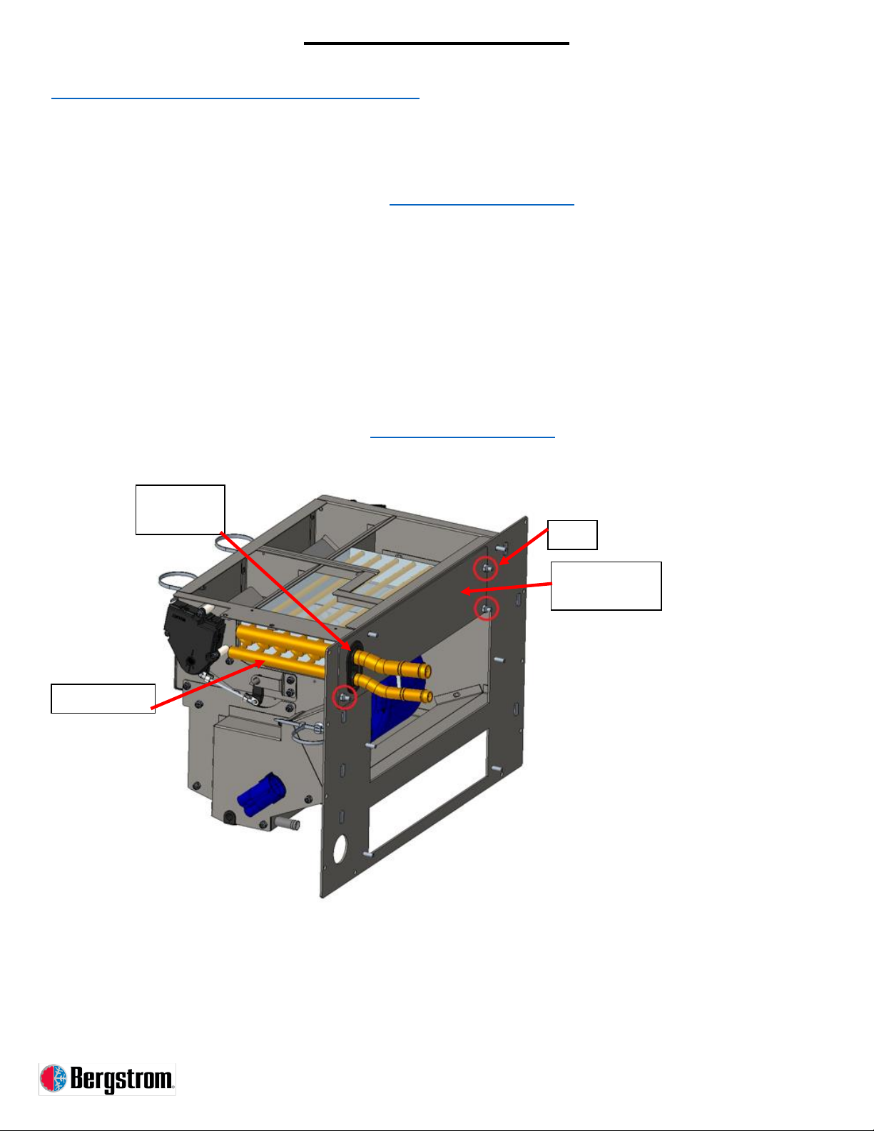
Component Servicing
Indoor HVAC Unit
Indoor HVAC Unit Removal
1. Remove outdoor HVAC unit. Refer to OUTDOOR HVAC UNIT
2. Drain engine coolant from heater core and connected heater hoses.
NOTE –Before removing heater hoses, label hoses to ensure correct installation.
3. Remove 2 spring clamps and disconnect both heater hoses from heater core tubes.
4. Use inside duct top access panel to remove 2 nuts and slide clamp plate away. Remove 2
screws on opposite side.
5. Remove 10 screws holding indoor unit to vehicle.
Indoor HVAC Unit Installation
1. Insert indoor unit and secure to vehicle with 10 screws.
2. Use inside duct top access panel to position clamp plate under top flange of indoor unit and
over the top of mode box, securing with 2 nuts. Secure 2 screws on opposite side.
3. Install heater hoses onto heater core tubes. Fill coolant system.
4. Install outdoor HVAC unit. Refer to OUTDOOR HVAC UNIT
Screw
Inside Duct Top
Access Panel
Nut
16
Component Servicing
Freeze Probe
Freeze Probe Removal
1. Remove outdoor HVAC unit. Refer to OUTDOOR HVAC UNIT
2. Gently pull freeze probe out of the face of the evaporator, noting probe depth and location of
indentation left behind.
3. Remove rubber grommet from side of HVAC module and from freeze probe.
4. Pull freeze probe out of HVAC module.
Freeze Probe Installation
1. Route new freeze probe thorough hole on side of HVAC unit.
2. Gently push freeze probe into the face of the evaporator at the same location and to the same
depth as noted during removal.
3. Secure rubber grommet around freeze probe wires and into the hole on the side of the HVAC
module.
4. Install outdoor HVAC unit. Refer to OUTDOOR HVAC UNIT
Freeze Probe
Rubber Grommet
17
Component Servicing
Fresh and Recirculation Air Filters
Fresh or Recirculation Air Filter Removal
1. Identify outdoor HVAC unit. It is the unit with the TXV.
2. Remove 1 screw and slide cover tabs out of slots.
3. Remove filter by pulling straight out of the door.
Fresh or Recirculation Air Filter Installation
1. Insert filter into respective area.
NOTE –Orient printed filter arrow with airflow direction as shown (towards unit).
2. Secure door by sliding tabs into slots and with 1 screw.
Fresh Air
Filter
Screw
Recirculation
Air Filter
Airflow
Direction
18
Component Servicing
Actuator(s)
Actuator Removal
1. Depending on actuator location, removal of outdoor or indoor unit may be necessary. Refer to
OUTDOOR HVAC UNIT and INDOOR HVAC UNIT
2. Disconnect electrical connector from the specific actuator that is being replaced (passenger
zone blend door actuator shown for reference).
3. Remove 3 nuts to remove actuator.
4. Check to make sure the 3 nylon spacers behind the actuator stay in place over the threaded
studs on the HVAC module.
5. Check to make sure the door adaptor piece stays located on the door rod protruding from the
HVAC module.
Actuator Installation
1. Secure actuator to HVAC unit using 3 nuts.
2. Connect electrical connector to actuator.
3. If necessary, install outdoor or indoor HVAC unit. Refer to OUTDOOR HVAC UNIT and
INDOOR HVAC UNIT
Door Adaptor
Nylon Spacers
Actuator
Nut

19
Component Servicing
Evaporator Coil
Evaporator Coil Removal
1. Remove outdoor HVAC unit. Refer to OUTDOOR HVAC UNIT
2. Remove evaporator access cover from the HVAC module by removing 6 nuts.
3. Remove freeze probe. Refer to FREEZE PROBE
4. Slide evaporator-TXV subassembly out of the HVAC module.
Evaporator Coil Installation
1. If A/C system is to be flushed, perform that operation before re-assembling the system. Refer
to REFRIGERANT CHARGE INFORMATION
NOTE –During installation, always lubricate O-rings on fittings with mineral-based oil.
2. Slide evaporator-TXV subassembly into the HVAC module.
3. Install freeze probe. Refer to FREEZE PROBE
4. Secure evaporator access cover using 6 nuts.
5. Install outdoor HVAC unit. Refer to OUTDOOR HVAC UNIT
Evaporator-TXV
Subassembly
Access Cover
Nut
20
Component Servicing
Heater Core (Indoor HVAC Unit)
Heater Core Removal
1. Remove outdoor HVAC unit. Refer to OUTDOOR HVAC UNIT
2. Remove heater access cover from indoor HVAC unit by removing 3 nuts.
3. Remove and retain rubber grommet from heater tubes and service cover.
4. Pull heater core out of the indoor HVAC unit.
Heater Core Installation
1. Push heater core into indoor HVAC unit.
2. Secure heater access cover using 3 nuts.
3. Secure rubber grommet into plate around tubes.
4. Install outdoor HVAC unit. Refer to OUTDOOR HVAC UNIT
Heater Core
Rubber
Grommet
Heater
Access Cover
Nut
Table of contents
Other Bergstrom Fan manuals


Popular Fan manuals by other brands


BrookVent
BrookVent AIRSTREAM XE+ Installation, maintenance and user manual

S&P
S&P ARTIC N GR Series User instructions

KDK
KDK M40R operating instructions

Euromatic
Euromatic KYT40-5 instruction manual

Zehnder Rittling
Zehnder Rittling ComfoAir 155 WM installation instructions

Sealey
Sealey HVF20PO instructions


