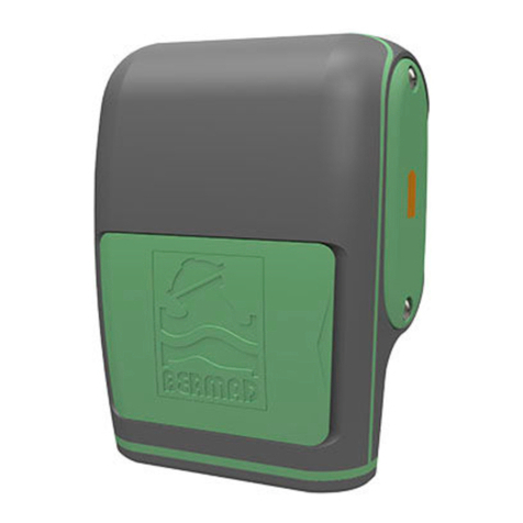
BERMAD BEC PM1 User manual

Water Control Solutions
Installation & Operation Manual
BEC PM1 Controller
Time/Flow/Volume Controller

2
Table of Contents
Introduction
4
Chapter 1
Technical Data and I/O Connections 6
DC Solenoid 6
Power Supply 6
Hydrometer or Water Meter 6
Flow Switch / Rain Sensor 7
Wiring Table 7
Switching the Controller's Operation Modes 8
Chapter 2
Pressure Management according to Flow-rate Application 9
Background 9
The Control Panel Display Icons
10
Programming Steps
11
Basic Settings
11
AUTO Operation
13
Chapter 3
Pressure Management according to
Time Intervals Application 14
The Control Panel 14
Display Icons 15
Programming Steps 16

3
Basic Settings 16
Application Description 18
Programming the Pressure Management by
Time Intervals Application 18
Chapter 4
On/O Control Application 20
Dead-end Pipes Purging Application Settings 20
Chapter 5
On/O Irrigation Application 26
Display Icons 26
Programming Steps 27
Basic Settings 27
Irrigation Program Settings 29
Volumetric Irrigation Program Parameters 30
Irrigation Program Common Parameters 31
Operational Screens 33
Alerts 34
Fault Messages Table 35
Buttons 35
General Information for All Applications 36
Monitoring 36
Manual Operations 37

4
Introduction
This document provides installation and operation instructions for
the BEC PM1 controller as it is used with BERMAD’s control valves in
Waterworks and Irrigation Applications.
Very Important:
Chapter #1 of this document provides general installation and
operation instructions which are common to all the applications’
types while the rest of the chapters are organized by application
type.
Therefore before installing and operating this controller please read
carefully chapter #1 and then jump to the chapter related to your
specific application:
Pressure Management Applications:
Optimizing water supply and reducing non revenue water by using
the BEC PM1 controller is done by connecting it to BERMAD’s two
step pressure reducing valve installed at the entry point of a district
metering area.
Chapter #2
Pressure management according to flow rate:
For switching between the two pre-set pressure regimes of the PRV
according to high or low flow demand at the controlled district please
refer to chapter #2 of this document.
Chapter #3
Pressure management according to time
intervals:
For switching between the two pre-set pressure regimes of the
PRV according to time settings please refer to chapter #3 of this

5
document.
Chapter #4
On/Off Control:
The BEC PM1 enables a volumetric control of BERMAD’s On/Off
control valves that are used for purging pipe’s dead ends, refreshing
reservoirs and other such On/Off applications. Please refer to chapter
#4 if your specific application in of an On/Off type.
Chapter #5
Irrigation Control:
The BEC PM1 controller can be used as a single station irrigation
controller for agriculture or gardening. Please refer to chapter #5 if
your specific application is of an irrigation type.

6
The following I/Os are used for BERMAD’s waterworks and Irrigation
Applications:
DC Solenoid:
Connect the solenoid’s wires to the cable coming out of the
controller’s first station port. Connect the solenoid’s RED wire to the
controller’s RED wire and the BLACK wire to the controller’s BLACK
wire.
Power supply:
Open the battery’s compartment lid and connect a good-quality 9
Volt alkaline battery, then firmly close the lid.
When the battery is first connected, the controller performs a self-
test, closes the DC solenoid and displays the first settings screen.
Under normal use, the battery should last for at least one season.
Hydrometer or Water Meter:
BERMAD’s 900 series Hydrometer, or a water meter with dry contact
pulse output, is used in applications such as the following:
nnPressure management with flow rate reference applications
where switching to the high pressure setting is done in case of a
high demand for water.
nnPipes’ dead-end purging applications where the purged-out water
is measured by volume and not by time.
nnIn cases of fire protection or volumetric irrigation applications.
Connect the two water meter pulse wires to the two controller’s
RED wires. Please note that there is no polarity significance in this
connection.
Chapter #1
Technical Data and I/O Connections

7
Wire
Color
Task Remarks
DC type solenoid - 9V-12V DC Latch - for pressure management
according to flow-rate
RED To be connected to the
solenoid's RED wire
This wire is joint together with
the solenoid's RED wire in the
controller's black cable
BLACK To be connected to the
solenoid's BLACK wire
This wire is joint together with
the solenoid's BLACK wire in
the controller's black cable
DC type solenoid - 9V-12V DC Latch - for pressure management
according to time interval
RED To be connected to the
solenoid’s BLACK wire
This wire is joint together with
the solenoid's BLACK wire in
the controller's black cable
BLACK To be connected to the
solenoid's red wire
This wire is joint together with
the solenoid's RED wire in the
controller's black cable
Water meter
RED
Connect one of the water-
meter's pulse wires to one of
the controller's RED wires
There is no polarity significance
in this connection
RED
Connect the other water-
meter's pulse wires to one of
the controller's RED wires
There is no polarity significance
in this connection
Flow switch (or rain sensor for irrigation applications)
YELLOW
Cut the YELLOW loop and
connect one of the flow
switch wires to one of the
controller's yellow wires.
There is no polarity significance
in this connection
YELLOW
Connect the other flow switch
wire to one of the controller's
YELLOW wires.
There is no polarity significance
in this connection
Flow Switch/Rain Sensor:
Flow switch can be used with the time controlled pressure
management application for switching to the high pressure setting in
case of a high demand for water, i.e. in case of fire.
Wiring Table:
The controller is supplied with the following wires connected to its
terminal strip:

8
Switching the Controller's Operation Modes
The BEC PM1 controller has two distinctive operation modes:
Irr mode - this is the default operation mode of the controller which
is used for Irrigation, Time Intervals Pressure Management and On/
off applications.
Pr mode - this mode is used for the Pressure Management according
to Flow-rate application only.
Switching between these two operation modes is done by
simultaneously pressing the and keyboard buttons.
For example:
Changing from “Irr” to “Pr” mode:
Press the and buttons simultaneously for 5 second, the
system displays the mode name and starts switching to the Pr
mode. Continue pressing the buttons for additional 3 seconds until
the software version appears on screen (in a form of a number)
then release the buttons. The controller is now on its “Pr” mode.
Please note that changing the controller’s mode requires about 10
seconds of continuous buttons pressing time in total.
Changing from “Pr” to “Irr” mode:
Keep pressing the and buttons for another 3 second,
the system displays the new mode name and switches back to
the Irr mode.
Important! Before operation the controller for the first time
make sure that it is set to the correct operation mode for your
specific application.

9
Background
This application enables the user to set a flow rate SET POINT in
number of pulses per hour. The application automatically changes
the control state of the Two Step Pressure Reducing Valve which is
controlled by the BEC PM1 controller according to the actual real-time
flow-rate reading.
When the actual flow rate reading crosses the SET POINT, the
controller starts counting a stabilization time delay parameter
for ensuring that the flow-rate crossing of the set-point is not a
temporary pressure fluctuation.
If by the end of the delay counting the flow-rate reading remains
beyond the set point the solenoid state changes.
There are two delay time parameters: One for LOW to HIGH flow
crossing of the set-point and the other for HIGH to LOW flow
crossing.
This application has four screens:
The first three screens are used for setting the SET POINT flow
reference [SP:PH] and the two values of the delay timers [SP:tH] &
[SP:tL].
The fourth screen is the automatic operation screen (“AUTO”) that is
used for monitoring the application operation.
Chapter #2
Pressure Management according to
Flow-rate Application

10
The Control Panel
UsageNameButton
Next Step button - used to
advance to the next screen
NEXT
Shift button - Not in use in this
application
SHIFT
Used for increasing a numeric
value
ON +
Used for switching between the
“Pr” and “Irr” operation modes
OFF -
Switch between Pressure
Management by Flow (“Pr”) and
Pressure Management by Time
(“Irr”) Applications
&
Display Icons
The following icons may appear on the screen
during programming or operation modes:
Pressure Management by Flow DescriptionIcon Symbol
Pressure Management indication
PM
Setting Mode
The last measured flow rate is higher than the
set point threshold [Pulses/Hour]
The last measured flow rate is lower than the
set point threshold [Pulses/Hour]
Automatic operation screen. Used for monitoring
the system operation

11
Programming Steps
Basic Settings:
Setting Flow Reference Set-point
Upon entering to this screen the display
shows the [SP:PH] (Set Point : Pulses per
Hour) title.
Use the or the buttons to set
the flow-rate value by number of pulses
per hour. This is the flow-rate that
distinguishes between high and low
pressure conditions.
Please note:
The flow reference entry ranges between 0 and 9999 pulses/hour.
The factory default value is 50 pulses per hour.
Press the button to move to the next screen.
Setting the Low to High flow stabilization delay timer
Upon entering to this screen the display
shows the [SP:tH]
(Set Point : High flow timer) title.
Use the or the buttons to set the
required delay time parameter which is
used for verifying that the change from
LOW flow to HIGH flow is stable.
Please note:
The timer values range between 0 and
60 minutes in 1 minute steps.
The factory default value is 1 minute.
Press the button to move to the next screen.
Fig.1 - Flow set-point
Fig.2 - High flow timer

12
Setting the High to Low flow stabilization delay timer
Upon entering to this screen the display
shows the [SP:tL]
(Set Point : Low flow timer) title.
Use the or the buttons to set the
required delay time parameter which is
used for verifying that the change from
High flow to Low flow is stable.
Please note:
The timer values range between 0 and
180 minutes in 1 minute steps.
The factory default value is 20 minutes.
Press the button to move to the next screen.
Fig.3 - Low flow timer

13
Auto operation
Monitoring
When no button is pressed in the controller’s keyboard for 3 minutes,
the controller moves to the main monitoring screen indicated by the
word AUTO in the middle of the screen. The AUTO screen displays the
following data items:
• The “AUTO” icon indicates that the
automatic Pressure Management
operation is active.
• The Display shows the current reading of
the system’s flow-rate.
• The Up arrow
indicates that the
current flow-rate is higher than the SET
POINT flow parameter.
High flow reading
• The DOWN arrow indicates that the
current flow-rate is lower than the SET
POINT flow parameter.
When the solenoid status is ON the
1
Icon appears
on the screen.
When the solenoid status is OFF the 1Icon disappears.
High flow reading
Low flow measurment

14
The Control Panel
The BEC PM1 Human-Machine Interface consists of a graphical display
screen and a four keys keyboard:
NEXT STEP button - Used to advance to the next screen
or programming step
SHIFT button - Used to sequentially change the focus
between the items of the current screen
PLUSE / ON button - Used to increase numeric data, set
on operation days and start manual operation
MINUS / OFF button - Used to decrease numeric data, set
off operation days and stop manual operation
Chapter #3
Pressure Management according to
Time Intervals Application

15
Display Icons
The following icons may appear on the display screen during
programming or operation modes:
High Flow
[seconds]
Setting Mode
Operation Days
Set Time / Time
Mode
Manual OperationVolumetric Mode
Uncontrolled Water
Meter [minutes]
Operation Time
Station Number
1
Automatic
Operation
Flow OFF
Seasonal
Adjustment
Low Battery
AL:bt
Stopped by Flow
Switch

16
Programming Steps
This chapter describes the required programming steps of the
controller and it is divided into three sections: Basic Settings,
Pressure management settings, and end of line flushing settings.
Basic Settings:
First Basic Settings Screen
The basic controller setting should be done once the controller is
wired to the system and the power is connected, or after a total
reset operation is performed. The first setting screen appears
displaying 3 optional settings:
1. Solenoid Type:
Upon initial start-up the connected solenoid type is checked by the
controller; it must be a DC latch solenoid.
2. Clock Mode:
Press the bbutton and set the system clock to 12 or 24 hour
clock. Factory default - 24h.
3. Time / Volume Operation:
Press the button and select the required operation mode. Select
TIME for BERMAD’s pressure management by time application.
Note the icons change according to your selection: the icon should
be selected for time operation. Factory default - Time.
Press the button to move to the next basic settings screen.
Second Basic Settings Screen
In the second setting screen the operator can set the Flow Switch
usage mode. Please note that a flow switch can be used only for
BERMAD’s pressure management by time intervals application.

17
Flow switch mode:
Press the button to enable or disable the flow switch operation.
When a flow switch is enabled the icon appears on screen.
Factory default - flow switch enabled.
Press the button to move to the next basic settings screen
Third Basic Settings Screen
The third setting screen is used for setting the system time and day
of the week.
System Time:
Use the and the buttons to set the system time. Hold the
button pressed to quickly advance the digits. Press both buttons
simultaneously to reset the time and day to the factory default
setting.
Day of the week:
Use the button to scroll through the days of the week and set
the current day.
Press the button to exit the basic settings screens and move to
the operation programming screens.

18
Pressure Management Application Settings
BERMAD’s pressure management by time application is based on
BERMAD control valve equipped with two pressure reducing pilots:
one for high pressure setting and the other for low pressure setting.
Normally the high pressure pilot controls the valve, while the low
pressure pilot is on standby mode. A BEC PM1 controller with a DC
solenoid can switch the high pressure pilot with the low pressure
pilot according to a pre-defined time based operation regime. Such
arrangement can switch the system to low pressure settings during
night, while maintaining high pressure during day time.
The system is also equipped with a high flow switch that can stop
the low pressure regime when higher demand for water is detected,
such as in case of fire.
The following chapter describes the programming steps required for
setting-up this application:
Programming the Pressure Management
by Time Intervals Application
The BEC PM1 operation programs consist of three parameters per
each valve program: Operation Time, Operation Days, and Start Time.
For controlling BERMAD’s Pressure Management by Time Interval
Application the controller is supplied with a single solenoid (valve),
operated by time with up to three start times a day, and with a flow
switch.
In municipal water systems the demand for water in residential
neighborhoods is high during the mornings and evenings and low
during the night and mid-day hours; therefore, the control valve is
set for the high pressure during high demand hours.
Operating the valve with the BEC PM1 controller reduces the
otherwise too high pressure settings during the low demand hours.

19
For example, in typical municipal pressure regime, the day low
pressure hours are between 10:00 AM and 06:00 PM and the night
low pressure hours are between 10:00 PM and 06:00 AM, during the
high demand hours the valve maintains the high pressure setting.
Therefore, the three required program parameters of the controller
are: Operation Time - 8 hours, Operation Days - 7 days and two Start
Times one at 10:00 AM and the other at 10:00 PM.
1. Operation Time:
Use the button to move to the Operation Time programming
screen, this is the screen with the blinking icon, the blinking
triangle with the digit 1 in it, and the icon. Use the buttons to
set the required operation time (8:00 hours in our example).
Press the button to move to the next programming screen
which is the Operation Days screen.
2. Operation Days:
Use the button to set a particular day as an operation day, or use
the button to skip the day, the cursor will advance to the next
day. In our example set all 7 week days for operation.
Press the button to move to the next programming screen
which is the Start Times screen.
3. Start Times:
Use the and the buttons to set the first required Start Timed
(10:00 AM in our example).
Press the button to move to the second Start Time and set it as
required (10:00 PM in our example).
The controller is now set for automatically operating the Pressure
Management by Time Intervals Application.

20
The BEC PM1 enables a volumetric or time based control of
BERMAD's On/Off control valves that are used for purging pipe's
dead ends, refreshing reservoirs and other such On/Off applications.
This chapter describes the Dead-end Pipes Purging Application
Settings.
Dead-end Pipes Purging Application
Settings
Due to operational conditions, in some municipal and industrial
water systems, there is a need for periodic purging of the systems
dead-ends of pipes for refreshing the water supply. BERMAD’s
control valves equipped with BEC PM1 controllers can be installed
in these systems. BERMAD’s Dead-end Pipes Purging Application
accounts for the purging out of the system. This task is automatically
performed based on three major parameters:
1. Purging interval - set at specific days of the week or
as day intervals
2. Amount of purged water - set by operation time or by volume
3. Start time - set for the operation day
(with up to three start times per such day)
The following examples depict three typical scenarios:
Chapter #4
On/O Control Application
Table of contents
Other BERMAD Controllers manuals
Popular Controllers manuals by other brands
Novanta
Novanta ScanMaster user manual
LOVATO ELECTRIC
LOVATO ELECTRIC RGK600 installation manual
Solid State Logic
Solid State Logic Nucleus user guide
Filtration Group
Filtration Group MFS-05 Translation of the original instructions
NI
NI PXI-8104 installation guide

Allen-Bradley
Allen-Bradley 1756-L5 Programming manual
