BERMAD Subtv User manual

Water Control Solutions
Installation & Operation Manual
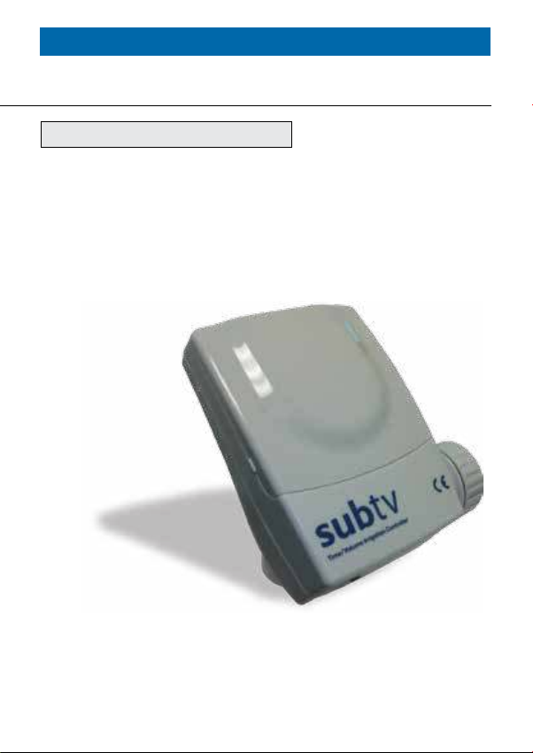
Subtv Controller
for BERMAD Waterworks Applications


Table of Contents
Introduction 3
Technical Data & Installation Instructions 4 - 5
Control Panel 6 - 7
Programming 8 - 16
Monitoring 17
Manual Operation 18

Introduction
Installation & Operation Manual
SUBtv - DC Volumetric One Station Controller
This document provides installation and operation instructions
for the Subtv controller as it is used with the following Bermad
control valves waterworks applications:
■Pilot change at High/Low pressure management application
■Dead end pipes purging application
Subtv Controller
for BERMAD Waterworks Applications

4
Technical data and installation instructions
The following I/Os are used for Bermad’s waterworks applications:
DC Solenoid:
Connect the solenoid wires to the cable coming out of the
controller’s first station port. Connect the solenoid’s RED wire
to the controller’s RED wire and the BLACK wire to the controller’s
BLACK wire.
Power Supply:
Open the battery compartment lid and connect a good quality
alkaline 9 Volt battery, then firmly close the lid. When the battery
is first connected, the controller performs a self-test, closes the
DC solenoid and displays the first settings screen. Under normal
use, the battery should last for at least one season.
Hydrometer:
Bermad’s 900 series Hydrometer, or a water meter with pulse
output, is used in pipes dead-end purging application where
the purged-out water is measured by volume instead of by time.
Connect the two water meter pulse wires to the two controller’s
RED wires. Please note that there is no polarity significance in this
connection.
Flow Switch:
Flow switch can be used with the pressure management
application for switching to the high pressure setting in case of
a high demand for water, i.e. in case of fire. In order to connect
a Normally Closed flow switch, cut the YELLOW wire loop coming
out of the controller and connect the cut wires to switch.
Wiring Schematic:
The controller is supplied with the following wires connected to
its terminal strip:

5
Wire Color Task Remarks
DC type solenoid - 9V-12V DC Latch
Red To be connected to the
solenoid's red wire
Joint together with the
solenoid's black wire in
a black cable
Black To be connected to the
solenoid's black wire
Joint together with the
solenoid's red wire in
a black cable
AC type solenoid - 24V AC
Red To be connected to one
of the solenoid's wires
Joint together with the
solenoid's black wire
in a black cable. No
polarity significance in this
connection.
Black To be connected to the
solenoid's black wire
Joint together with the
solenoid's red wire in
a black cable. No polarity
significance in this
connection.
Water meter
Red
Connect one of the water-
meter's pulse wires to one
of the controller's red wires.
There is no polarity
significance in this
connection.
Red
Connect the other water-
meter's pulse wire to the
second controller's red wire.
There is no polarity
significance in this
connection.
Flow switch
Yellow
Connect one of the flow
switch wires to one of the
controller's yellow wires.
There is no polarity
significance in this
connection.
Yellow
Connect the other flow
switch wire to the second
controller's yellow wire.
There is no polarity
significance in this
connection.

6
The Control Panel
The Subtv Human-Machine Interface consists of a graphical
display screen and a four keys keyboard:
NEXT STEP button - Used to advance to the next
screen or programming step
SHIFT button - Used to sequentially change the focus
between the items of the current screen
PLUSE / ON button - Used to increase numeric data,
set on operation days and start manual operation
MINUS / OFF button - Used to decrease numeric data,
set off operation days, and stop manual operation
7
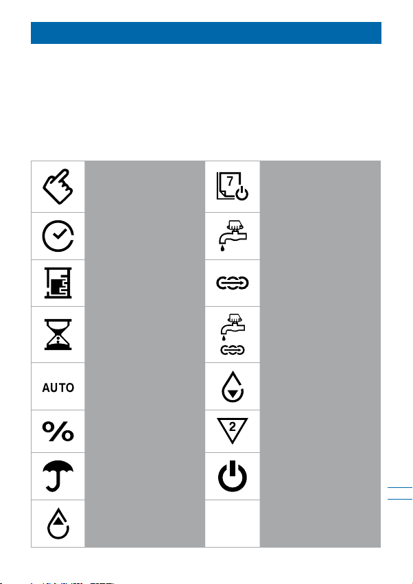
Display Icons
The following icons may appear on the display screen during
programming or operation modes:
Please note:
Some of the following icons are not related to BERMAD applications.
Operation DaysSetting Mode
Manual Operation
Set Time /
Time Mode
Sequential ProgramVolumetric Mode
Semi Auto seq.
Operation
Operation Time
Uncontrolled Water
Meter
Automatic Operation
Station Number
Seasonal
Adjustment
Flow OFF / Low
Battery
Stopped by Flow
Switch
High Flow (seconds)

8
Programming Steps
This chapter describes the required programming steps of the
controller and it is divided into three sections: Basic Settings,
Pressure management settings, and end of line flushing settings.
Basic Settings:
First Basic Settings Screen
The basic controller setting should be done once the controller
is wired to the system and the power is connected, or after a total
reset operation is performed. The first setting screen appears
displaying 3 optional settings:
1. Solenoid Type:
Upon initial start-up the connected solenoid type is checked
by the controller; it must be a DC latch solenoid for BERMAD
applications. The word dC appears on screen indicating that
the type of solenoid found is DC. When the controller is operated
by a 9V battery the solenoid type is DC only and it cannot be
changed by the operator.
2. Clock Mode:
Press the button and set the system clock to 12 or 24 hour
clock. Factory default - 24h.
3. Time / Volume Operation:
Press the button and select the required operation mode.
Select TIME for BERMAD’s pressure management application
and VOLUME for BERMAD’s purging application.
Note the icons change according to your selection:
for time operation and for volumetric operation.
Factory default - Time.
Press the button to move to the next basic settings screen.
9
Second Basic Settings Screen
In the second setting screen the operator can set the Flow Switch
usage mode. Please note that a flow switch can be used only for
BERMAD’s pressure management application.
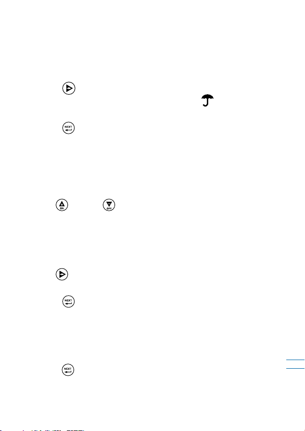
Flow switch mode:
Press the button to enable or disable the flow switch
operation. When a flow switch is enabled the icon appears
on screen. Factory default - flow switch enabled.
Press the button to move to the next basic settings screen.
Third Basic Settings Screen
The third setting screen is used for setting the system time and
day of the week.
System Time:
Use the and the buttons to set the system time.
Hold the button pressed to quickly advance the digits.
Press both buttons simultaneously to reset the time and day
to the factory default setting.
Day of the week:
Use the button to scroll through days of the week and set
the current day.
Press the button to exit the basic settings screens and move
to the operation programming screens.
Total Reset Operation
In order to return the controller to its factory defaults setting,
erasing the memory, and restarting the controller operation,
press the button for at least 6 seconds.

10
Pressure Management Application Settings
BERMAD’s pilot switch pressure management application is
based on a series 700 control valve equipped with two pressure
reducing pilots: one for high pressure setting and the other for low
pressure setting. Normally the high pressure pilot controls the
valve, while the low pressure pilot is on standby mode. A Subtv
controller with a DC solenoid can switch the high pressure pilot
with the low pressure pilot according to a pre defined time based
operation regime.
Such arrangement can switch the system to low pressure
settings during night, while maintaining high pressure during
day time.
The system is also equipped with a high flow switch that can stop
the low pressure regime when higher demand for water is
detected, such as in case of fire.
The following chapter describes the programming steps required
for setting-up this application:
Programming a Pressure Management Application
The Subtv operation programs consist of three parameters
per each valve program: Operation Time or Volume, Operation
Days, and Start Time.
For controlling BERMAD’s Pressure Management Application
the controller is supplied with a single solenoid (valve), operated
by time with up to three start times a day, and with a flow switch.
In municipal water systems the demand for water in residential
neighborhoods is high during the mornings and evenings and low
during the night and mid day hours; therefore, the control valve
is set for the high pressure during high demand hours.
11
Operating the valve with the Subtv controller reduces the too
high pressure settings during the low demand hours.
For example, in typical such pressure regime, the day low
pressure hours are between 10:00 AM and 06:00 PM and the
night low pressure hours are between 10:00 PM and 06:00 AM,
during the high demand hours the valve maintains the high
pressure setting.
Therefore, the three required program parameters of the controller
are: Operation Time - 8 hours, Operation Days - 7 days and two
Start Times one at 10:00 and the other at 18:00.
1. Operation Time:
Use the button to move to the Operation Time programming
screen, this is the screen with blinking icon, blinking triangle
with the digit 1 in it, and the icon. Use the and the
buttons to set the required operation time (8:00 hours in our example).
Press the button to move to the next programming screen
which is the Operation Days screen.
2. Operation Days:
Use the to set a particular day as an operation day, the cursor
will advance to the next day. In our example set all 7 week days
for operation.
Press the button to move to the next programming screen
which is the Start Times screen.
3. Start Times:
Use the and the buttons to set the first required Start
Timed (10:00 in our example).
Press the button to move to the second Start Time and set
it as required (22:00 in our example).
The controller is now set for automatically operating the Pressure
Management Application.

12
Dead-end Pipes Purging Application Settings
Due to operational conditions, in some municipal and industrial
water systems, there is a need for periodic purging of the
systems dead-ends of pipes for refreshing the water supply.
BERMAD’s control valves equipped with Subtv controllers can be
installed in these systems. BERMAD’s Dead-end Pipes Purging
Application accounts for the purging out of the system. This task
is automatically performed based on three major parameters:
1. Purging interval - set at specific days of the week or as
day’s interval
2. Amount of purged water - set by operation time or by volume
3. Start time - set for the operation day (with up to three start
times per such day)
The following examples depict three typical scenarios:
A. Purging interval by Days of the Week and purging
amount by operation time:
In this example the pipe needs to be purged for 5 minutes every
Monday and Friday at 08:00 AM. Therefore, the three required
program parameters of the controller are: Operation Time - 5
Minutes, Operation Days - Monday and Friday, and Start Time
at 08:00 AM.
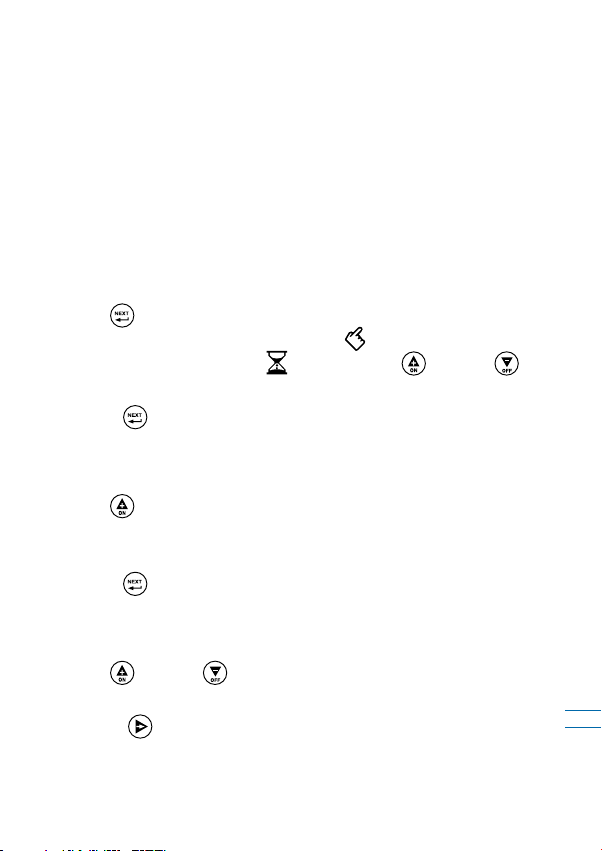
1. Operation Time:
Use the button to move to the Operation Time programming
screen - this is the screen with blinking icon, blinking triangle
with the digit 1 in it and the icon. Use the and the
buttons to set the required operation time (00:05 minutes in
our example).
Press the button to move to the next programming screen
which is the Operation Days screen.

13
2. Operation Days:
Use the to set a particular day as an operation day, the cursor
will advance to the next day. In our example set Monday and
Friday for operation.
Press the button to move to the next programming screen
which is the Start Times screen.
3. Start Time:
Use the and the buttons to set the required Start Time
(08:00 in our example).
The controller is now set for automatically operating this Dead
end Pipes Purging Application.
B. Purging interval by Days Interval and purging amount
by operation time:
In this example the pipe needs to be purged for 5 minutes every
10 days at 08:00 AM. Therefore the three required program
parameters of the controller are: Operation Time - 5 Minutes,
Operation Interval - 10 days, and Start Time at 08:00 AM.
1. Operation Time:
Use the button to move to the Operation Time programming
screen - this is the screen with blinking con, blinking triangle
with the digit 1 in it and the icon. Use the and the
buttons to set the required operation time (00:05 minutes in
our example).
Press the button to move to the next programming screen
which is the Operation Days screen.

14
2. Operation Interval:
On the days of the week screen press the button to 7 times
for skipping the operation by days of the week and advancing
the cursor to the Days Cycle line. Two numbers appear on this
line: the right number presents the program’s Days Interval
and the left number display the number of days left till the next
operation day. Note that during the first setup of this program
the number of day till next operation number is zero.
Use the and the buttons to set the required Days Interval
(10 days in our example). Note that the maximal interval is
30 days.
Press the button to move to the next programming screen
which is the Start Times screen.
3. Start Time:
Use the and the buttons to set the required Start Time
(08:00 in our example).
The controller is now set for automatically operating this
Dead-end Pipes Purging Application.
C. Purging interval by days of the week and purging
amount by Water Volume:
In this example the pipe needs to be purged for 50 water
meter pulses every Monday and Friday at 08:00 AM. Therefore,
the three required program parameters of the controller are:
Operation Volume - 50 pulses, Operation Days - Monday and
Friday, and Start Time at 08:00 AM.
In order to operate the above program the system should be
based on BERMAD’s series Hydrometer, or on other BERMAD’s
control valve and a water meter. The Subtv controller should be
also set to volumetric operation, which can be done only at the

15
initial setup process of the controller (when power is connected
or when the controller’s reset operation is performed).
1. Operation Volume:
Make sure that the controller is configured for Volume operation
as described in the BASIC SETTINGS chapter at the beginning
of this document.
Once a Volumetric operation is set on the first setup screen,
press the icon to move to the next water meter setting
screen. This screen allows the user to set the following water
meter parameters:
High Flow Rate (H.F.R.) - indicated by the on-screen icon.
This parameter defines the minimal allowed time between two
water meter pulses. When pulses are received in shorter interval
than this parameter a High Flow indication is presented by the
controller and the operation stops. (See the fault messages
paragraph in the monitoring chapter below.) The factory default
is 60 seconds; use the and the buttons to set the required
H.F.R. parameter.
Press the button to move to the next water meter
setup parameter.
Timer Override (T.O.R.) - indicated by the on-screen icon.
This parameter defines the maximal allowed time between two
water meter pulses. When pulses are received in longer interval
than this parameter a water meter malfunction indication is
presented by the controller and the operation stops. (See the fault
messages paragraph in the monitoring chapter below.)
The factory default is 10 minutes; use the and the buttons
to set the required T.O.R. parameter.
Press the button to move to the next water meter
setup parameter.

16
Fill-Up Time (F.U.T.) - indicated by the on-screen icon.
This parameter defines the time it takes to fill-up the system
pipes at the beginning of the valve operation. During this time
the system does not enter to High Flow fault. In purging systems
where the purged water is released by open-end pipe to the
atmospheric pressure, the flow rate can be high. Make sure
that the F.U.T. and the H.F.R. parameters are correctly set for
your system requirements. The F.U.T. factory default value is
6 minutes and it can be changed by the and buttons.
Press the button to move to the next programming screen.
Move to the Operation length programming screen, this is the
screen with blinking icon, blinking triangle with the digit 1
in it, and the icon. Use the and the buttons to set
the required operation volume (050 pulses in our example).
Press the button to move to the next programming screen
which is the Operation Days screen.
2. Operation Days:
Use the to set a particular day as an operation day, the cursor
advances to the next day. In our example set Monday and Friday
for operation.
Press the button to move to the next programming screen
which is the Start Times screen.
3. Start Time:
Use the and the buttons to set the required Start Time
(08:00 in our example).
The controller is now set for automatically operating this
Dead-end Pipes Purging Application.

17
Monitoring
When no button is pressed in the controller’s keyboard for
3 minutes, the controller moves to the main monitoring screen
indicated by the word AUTO in the middle of the screen.
The AUTO screen displays the current status of the controller,
which includes the current time and day, as well as the opened
valve indication and its remaining operation time or volume.
During a fault or malfunction mode the relevant fault message
overrides the AUTO screen data, see the faults table below.
To cancel the fault check the system for the cause of the fault,
repair the necessary components and then press the and
the buttons simultaneously for 2 seconds.
Please note:
■When a fault message is displayed on the AUTO screen moving
to the other screens is not possible.
■In case the controller has more than one fault, this screen
alternates the current fault messages every few seconds.
Fault Messages Table
Type Display Operation stopped at: Remarks
Low Battery "AL:bt" All Valves (!) "OFF" icon is lit
Too High
Current
Usage
"AL:Cr" The faulty valve only The valve's
number icon is lit
High Flow "AL:HF" The faulty valve only The valve's
number icon is lit
Timer
Override "AL:tr" All Valves (!) Automatically canceled
at midnight

18
Manual Operation
The operator may manually start / stop the operation of the valve
at the manual operation screen.
Move to the manual operation screen by pressing the button
at any screen for 2 seconds. The icon appears.
Use the and the buttons to start or stop the operation
of the valve. Please note that when manually started, the valve
operates for the duration of its programmed operation time or
operation volume.
Disclaimer
The Subtv is a general purpose controller supplied as an
electronic device controlling BERMAD valves. Therefore this
document is limited to BERMAD’s applications only.
Table of contents
Other BERMAD Controllers manuals


Popular Controllers manuals by other brands


Extron electronics
Extron electronics PC 101 Setup guide

Envirowise
Envirowise D30 Installer's and owner's manual

YASKAWA
YASKAWA Motoman DX200 instructions

EuroLite
EuroLite D-4 user manual

Linak
Linak Deskline DL7 system user manual

Sentera Controls
Sentera Controls MTP-D010 Series Mounting and operating instructions