BERMAD FP-60F-D User manual

BERMAD Fire Protection
Strainers
Approvals
Typical Applications
■Water spray systems
■Deluge systems
■Fire monitors
■Automatic sprinkler systems
■ Foam proportioner/generator provided in the water line
■Upstream of Pressure Control valves
■Upstream of a Sensitive System Devices
Options
Consult BERMAD for other Materials of Construction
or other available specifications.
The BERMAD FP-60F-D/DV Basket Strainers are
intended to be installed in fire protection pipelines
primarily to prevent the clogging of fire sprinkler
nozzles and other debris sensitve components in
water or foam fire systems.
The BERMAD FP-60F-D/DV is designed for in-line
maintenance available with a large diameter flushing
outlet for easy screen cleaning and simple screen
basket extraction, requiring only cover removal.
The ratio of the FP-60F-D/DV strainer’s basket screen
area to the inlet pipe area is more than 10:1, ensuring
continued system performance, a low pressure drop
and longer intervals between cleaning.
NFPA 11, 13, 15 and 16 standards state that listed strainers
shall be provided in the main pipeline of all systems
using nozzles where the water is likely to contain
obstructive material.
Features and Benefits
■UL-Listed and ULC size for Fire systems
■
Low pressure drop – Safety and reliability, ensures firewater
availability
■
Easy in-line maintenance – Large diameter flushing valve
for fast and easy interim cleaning
■
Suitable to prevent clogging – Nozzles, sprinklers or
other types of fire system discharge outlets. Designed
to trap foreign material of 3.2mm (
1
/
8
") diameter or larger
■
Large screen basket – Large basket area, Increasing
system reliability and safety
■
Suitable for installation in varied orientations - Refer to
installation and maintenance section
■
Compatible for use with corrosive fluids and harsh
environments – High Build Epoxy coated body/cover
and stainless steel 316 screen
■
Suitable for Foam Systems – For use with foam
proportioners or foam generators in compliance with
NFPA 11 requirements.
UL-Listed 3" through to 16"
Strainers, Pipeline (HLCV)
ULC Certified for Canada 3" through to 16"
Strainers, Pipeline (HLCV7)
Fire Line Basket Strainer
with Flushing Drain
Model FP-60F-D/DV
Model FP-60F-D/DV
Model FP-60F-DV
(14 & 16")
Model FP-60F-D
(14 & 16")
VdS (in process)
VdS (in process)
Model FP-60F-D Model FP-60F-DV
BERMAD Fire Protection
Strainers
FP-60F-D/DV
Design Engineer Guide
The BERMAD FP-60F-D/DV Basket strainers are for use in firewater supply and are capable of preventing the entrance
of solids that might block or clog fire protection nozzles or other sensitve devices.
Install the FP-60F-D/DV strainer upstream of the sprinkler valve, deluge valve, pressure control valve or any other
debris sensitive system device.
The Strainer must be located where there is adequate clearance for removal of the basket screen assembly to enable
easy extraction and inspection of the strainer basket.
Install the strainer such that there will be adequate drainage for the release of water when opening the strainer for
service and for the dirty water exhausted during the cleaning of the strainer screen using the flushing valve.
The flushing drain connection should be typically fitted with an appropriately sized normally closed valve and drain piping.
Where a flushing valve is to be employed, the FP-60F-D/DV Basket Strainer sizes 3" to 12" are recommended to be installed
in a horizontal position with the strainer cover and flushing valve to the side. To facilitate flushing for 14" and 16" sizes
installation is recommended to be vertical.
The strainers shall be installed and maintained in compliance with the NFPA-25 standard in the addition to the instructions
given by the authorities having jurisdiction.
The NFPA-11 standard requires that a listed strainer with a screen area to pipe cross section area ratio of 10:1 shall be used with
foam proportioners or foam generators, and should be installed in the water pipeline upstream of the water control valve.
The NFPA 13, 15 and 16 standards stipulate that a Listed Strainer shall be provided in the main pipeline of all systems
utilizing nozzles with waterways less than
3
⁄
8
" (9.5 mm) and for any system where the water is likely to contain obstructive
material. Strainers shall be capable of removing from the water all solids of sufficient size to obstruct the nozzles.
Engineer Specifications
The Fire Line Strainer shall be a basket type strainer UL listed.
The strainer shall be with high flow capacity and low pressure loss.
The strainer shall include a flushing valve capable of quickly and efficiently cleaning the strainer screen without removing
the strainer cover, or closing system pressure.
The strainer body and cover shall be ductile iron ASTM A536 65-45-12 with anti-corrosion Fusion Bonded High Build
Epoxy RAL 3002 coating internally and externally, all other wetted parts shall be stainless steel 316.
The screen shall be inline removable basket type, made of stainless steel 316 with screen holes diameter of 3.2 mm
(1/8"), meeting the requirements of the NFPA codes and standards. The Strainer basket screen area shall be at least 10:1
compared to the cross-sectional area of the pipeline.
Strainer maintenance, inspection or service shall be carried out in-line and without disassembly of the strainer body
from the pipeline. The Strainer shall be supplied pre-assembled with stainless steel bolting and hydraulically tested by
a factory certified by the ISO-9001 standard.
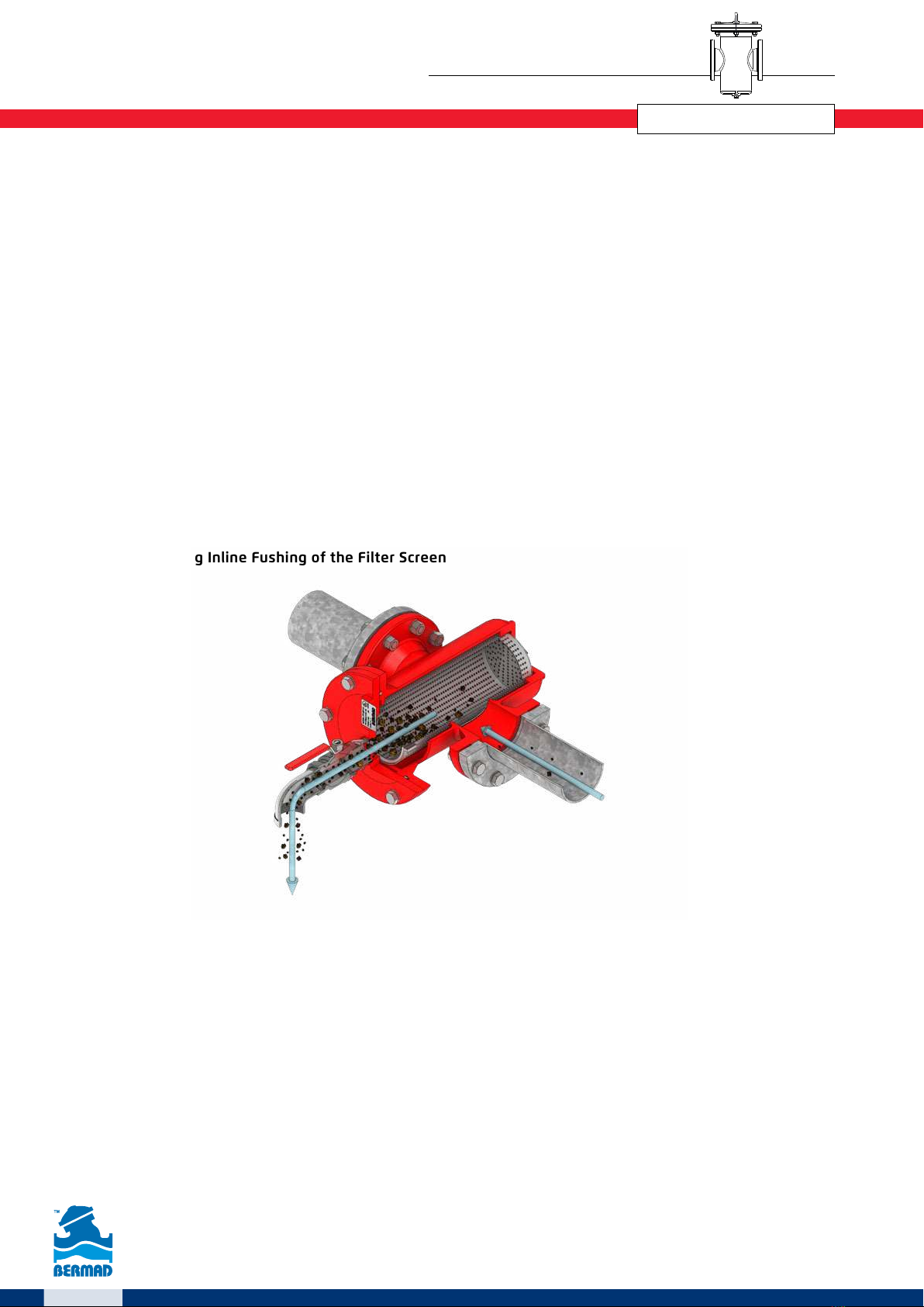
Cross Section Showing Inline Fushing of the Filter Screen

BERMAD Fire Protection
Strainers
FP-60F-D/DV
Installation
Provide basket removal clearances and strainer installation provisions in accordance with the requirements given in
the Design Engineer Guide section above. Install the strainer with the flow arrow on the body pointing in the desired
flow direction.
The strainer should be installed such that the flushing valve Drain Flange is at the lowest point of the strainer, 3" to
12" strainers have the flushing valve port on the cover that can be rotated to be at the lowest point, this is to facilitate
efficient cleaning of the screen while flushing.
The strainer shall be installed on the pipeline upstream of the sprinklers, pressure control valve, deluge valve or any
other sensitive system device. Install a listed isolating valve upstream of the strainer. An adequate support shall be
provided to carry the system installation as well as the dynamic loads.
It is recommended to install a differential pressure gauge rooted to upstream and downstream of the FP-60F-D/DV
strainer, in order to show the degree of strainer blockage. The maximum allowable differential pressure across the
strainer is 7 psi or 0.5 bar at maximum system flow.
Placing In Service
Verify that all strainer cover bolts are well tightened, close the drain plug and/or drain valve, slowly open the supply-
isolating valve and check that there are no leakages. Observe the system pressure gauge: it should indicate that the
normal supply of water pressure is maintained.
Typical Installations
The BERMAD FP-60F-D/DV strainer is ideal to be installed
upstream of the BERMAD Pressure Control Valve, preventing
the fouling of valve sealing surfaces and keeping the
waterways clear from obstructions.
The BERMAD FP-60F-D/DV strainer should be installed
upstream of the Deluge, Foam system or Automatic Sprinkler
system, preventing debris particles from clogging the
nozzles and other sensitve devices.
Automatic Pressure Control SystemDeluge / Sprinkler System

BERMAD Fire Protection
Strainers
FP-60F-D/DV
Maintenance
The following inspection procedure must be performed as indicated, in addition to specific requirements of any applicable
standards. Any damage or performance deficiency must be immediately corrected.
The fire system shall be inspected, tested, and maintained by qualified service personnel in accordance with local
requirements and/or national codes.
Preventive Maintenance
The frequency of inspection is dependant on the quality of the firewater, even so it is recommended that the strainer's
basket screen be removed and cleaned at least annually in addition to flushing after each operation or system flow test.
For the model FP-60F-DV that includes a flushing drainvalve, strainer cover removal for cleaning may be avoided
when a differential pressure gauge / transmitter across the strainer is provided. This device will indicate if the pressure
differential is satisfactorily below the maximum allowable 7 psi (0.5 bar) across the strainer screen at the maximum
system flow rate. If so, this shows that the screen is not dangerously blocked and a flush cleaning with the drain valve
should prove sufficient. However it is recommended to remove the strainer cover at least annually for inspection.
Inspection and Cleaning
Verify that the strainer is depressurized and drained before the disassembly of any strainer component.
The strainer basket screen should be cleaned after each system operation or flow test and during routine inspections,
as follows:
For strainers fitted with a flushing valve:
1. Fully open the flushing drain valve for at least 5 seconds or until the flushed water becomes visibly clear.
2. Close the flushing valve tight.
For periodic inspection and cleaning of screens for strainers without a flushing valve:
1. The system must be shut down and completely drained.
2. Remove the strainer cover and the basket screen.
3. Clean out the basket screen, as well as the interior of the strainer body.
4. Reinstall the basket screen, make sure that the basket is fully inserted into the strainer body and is correctly orientated.
5. Inspect the gasket O-ring and replace if needed.
6. Reinstall the strainer cover, gradually cross tighten diametrically and sequentially all bolts so as to apply uniform load
for the cover seal.
Construction Materials
MaterialDescriptionItem
Ductile Iron ASTM A536 65-45-12, Coated*Body1
Ductile Iron ASTM A536 65-45-12, Coated*Cover2
EPDM, Asbestos FreeO ring3
Stainless steel 304Bolting4
Stainless steel 316LScreen5
Stainless steel 304Lifting Eye6
Stainless steel 316Drain Plug7
Ductile Iron ASTM A536 65-45-12, Coated*Drain Flange (6" - 16")8
2" ISO-7-Rp Stainless steel 316Drain Plug (3 & 4")9
Stainless Steel 304Data Plate10
* Coating: High Build Fusion Bonded Epoxy RAL 3002, internal and external.
Sizes: 3" to 12" Horizontal Installation Sizes: 14 & 16" Vertical Installation
4
8
3
9
2
5
3
1
7
6

BERMAD Fire Protection
Strainers
FP-60F-D/DV
A
B
L
F
W
C
A
B
W
F
L
C
Dimensions and Weights
Sizes: 14" and 16" with side flushing port
Sizes : 3" through to 12"
Size 3" 4" 6" 8" 10" 12" 14" 16"
DN 80 100 200 200 250 300 250 300
Units mm in mm in mm in mm in mm in mm in mm in mm in
L 250 9.8 292 11.5 378 14.9 476 18.7 560 22.0 680 26.8 768 30.2 845 33.3
A 346 13.6 440 17.3 623 24.5 718 28.3 774 30.5 989 38.9 1125 44.3 1215 47.8
B 184 7.2 228 9.0 334 13.1 388 15.3 416 16.4 502 19.8 515 20.3 554 21.8
W 215 8.5 280 11.0 355 14.0 440 17.3 540 21.3 620 24.4 665 26.2 720 28.3
C 20 0.75 25 1 25 1 40 1.5 40 1.5 50 2 40 2 50 2
D 3.2 0.13 3.2 0.13 3.2 0.13 3.2 0.13 3.2 0.13 3.2 0.13 3.2 0.13 3.2 0.13
Flushing Valve
Length* 226 8.9 226 8.9 203 8 203 8 203 8 203 8 229 9 254 10
F 2" ISO-7-Rp 2" ISO-7-Rp 3" #150 3" #150 3" #150 3" #150 4" #150 6" #150
Weight kg/lbs 23 / 51 42 / 93 72 / 159 130 / 287 190 /419 285 / 628 / 628 417 / 919 531 / 1168
* For 3 & 4" strainers the dimension includes a 90º angle spout, for 6" to 16" the dimension is for the flushing valve only

BERMAD Fire Protection
Strainers
FP-60F-D/DV
www.bermad.com
© Copyright 2010-2020 Bermad CS Ltd. All Rights Reserved. The information contained in this document is subject to change without notice.
BERMAD shall not be liable for any errors contained herein. March 2020
1
24000
55
5
5
Pressure Loss
Flow
2
3
4
7
4
3
2
7
3
2
5
0.3
0.5
15
4
7
8
9
6
0.6
0.7
0.8
0.9
0.4
0.2 gpmm3/hpsibar3730 73
1
1
0.1
20
352000 3000 5000
70 700
50 7000 20
0.1
1.0
0.01
100 1000 2000 4000
200
2050500
0.05
0.5
Pressure Loss
Flow
0.2
0.3
0.4
0.7
0.04
0.03
0.02
0.07
3
2
5
0.3
0.5
15
4
7
8
9
6
0.6
0.7
0.8
0.9
0.4
0.2 gpmm3/hpsibar3070300700 3000
10
1
0.1
200
100 1000 10000
300 500 2000 3000 5000
70 700
50
7000 20000
Technical Data
■Available sizes UL-Listed: 3, 4, 6, 8, 10, 12, 14 and 16"
■Other available sizes, w/o flushing port: 18, 20 and 24"
■End connections standard: ANSI B16.42 #150RF
■UL-Listed pressure rating:
3 - 12": 200 psi (14 bar)
14 - 16": 250 psi (17.2 bar)
■Design pressure: 300 psi (20.7 bar)
■Pressure drop: 3 psi at 15 ft/sec (0.2 bar at 4.57 m/sec)
approx, with clean screen, see also note 3
■Temperature rating: 90˚C / 194˚F
■Max allowable differential pressure:
7 psi / 0.5 bar (note 3)
■Screen hole diameter:
1/8inch (3.2 mm)
■Basket screen area to pipe cross-sectional area ratio:
10:1 (min)
■Basket screen free flow area to basket screen area:
40% (min)
■Flushing/Blow-Off port diameter:
3" & 4" strainers 2" Threaded,
6" to 12" strainers 3" #150 Flange,
14" strainer 4" #150 Flange
16" strainer 6" #150 Flange
(1) Flow coefficient Kv: flow in m³/h at 1 bar differential pressure, Cv: flow in gpm at 1 psi differential pressure; The pressure loss calculation formula: Δp = SG (Q/ Cv or Kv)2
(2) Leq: Equivalent pipe length for turbulent flow in clean commercial steel pipe (SCH 40)
(3) Max allowable pressure drop: 7 psi (0.5 bar) across the strainer, basket screen shall be cleaned when pressure drop exceeds this value at maximum flow
Notes:
Size 3" 4" 6" 8" 10" 12" 14" 16"
Units metric US metric US metric US metric US metric US metric US metric US metric US
Kv(1) / Cv(1) 168 194 275 317 551 636 1001 1156 1665 1923 2027 2341 2534 2927 3339 3857
Leq (2) m
/
ft 9 30 14 46 28 93 36 118 43 140 70 228 73 240 85 279
Flow Properties
Ordering Information
Size in/DN FP-60F-D Strainer Code
Part Number
3"/80 FP-3"-60F-01-H-C-A5-ER-D 60F03HCA5N00001-D-ER
4"/100 FP-4"-60F-01-H-C-A5-ER-D 60F04HCA5N00001-D-ER
6"/150 FP-6"-60F-01-H-C-A5-ER-D 60F06HCA5N00001-D-ER
8”/200 FP-8"-60F-01-H-C-A5-ER-D 60F08HCA5N00001-D-ER
10”/250 FP-10"-60F-01-H-C-A5-ER-D 60F10HCA5N00001-D-ER
12”/300 FP-12"-60F-01-H-C-A5-ER-D 60F12HCA5N00001-D-ER
14”/350 FP-14"-60F-01-H-C-A5-ER-D 60F14HCA5N00001-D-ER
16”/400 FP-16"-60F-01-H-C-A5-ER-D 60F16HCA5N00001-D-ER
Size in/DN FP-60F-DV Strainer
w/Flushing Valve Code Part Number
3"/80 FP-3"-60F-01-H-C-A5-ER-DV 60F03HCA5N00001-DV-ER
4"/100 FP-4"-60F-01-H-C-A5-ER-DV 60F04HCA5N00001-DV-ER
6"/150 FP-6"-60F-01-H-C-A5-ER-DV 60F06HCA5N00001-DV-ER
8”/200 FP-8"-60F-01-H-C-A5-ER-DV 60F08HCA5N00001-DV-ER
10”/250 FP-10"-60F-01-H-C-A5-ER-DV 60F10HCA5N00001-DV-ER
12”/300 FP-12"-60F-01-H-C-A5-ER-DV 60F12HCA5N00001-DV-ER
14”/350 FP-14"-60F-01-H-C-A5-ER-DV 60F14HCA5N00001-DV-ER
16”/400 FP-16"-60F-01-H-C-A5-ER-DV 60F16HCA5N00001-DV-ER
Flow Chart
This manual suits for next models
1
Table of contents
Popular Protection Device manuals by other brands

Symantec
Symantec DLP-S500 quick start guide

Hubbell
Hubbell Circuit Guard GFP15M operating instructions

Honeywell
Honeywell HOWARD LEIGHT IMPACT SPORT 1013530 User instructions

Fahl
Fahl LARYVOX TAPE Instructions for use

Schörghofer & Frehe
Schörghofer & Frehe Plisse manual

ensto
ensto Arcteq AQ-L310 instruction manual


Gardigo
Gardigo Vario 90801 instruction manual

SICK
SICK deTec2 Core Mounting instructions

Global Power Products
Global Power Products SURGE SAFE SM Series Installation, operation and maintenance manual

Arcteq
Arcteq AQ 200 Series instruction manual

Arcteq
Arcteq AQ-G215 instruction manual

ABB
ABB REB670 Series Applications manual