Bernecker + Rainer 4XP0000.00-K64 Guide

4XP0000.00-K64
Technical documentation
Version: 1.40 (March 2017)
4XP0000.00-K64
All information contained in this manual is current as of its creation/publication. We reserve the right to change
the contents of this manual without notice. The information contained herein is believed to be accurate as of
the date of publication; however, Bernecker + Rainer Industrie-Elektronik Ges.m.b.H. makes no warranty, ex-
pressed or implied, with regard to the products or documentation contained within this manual. In addition,
Bernecker + Rainer Industrie-Elektronik Ges.m.b.H. shall not be liable for any incidental or consequential damages
in connection with or arising from the furnishing, performance or use of the product(s) in this documentation. Soft-
ware names, hardware names and trademarks are registered by their respective companies.

Table of contents
2 Data sheet V1.40 4XP0000.00-K64
1 Views.......................................................................................................................... 3
2 General information.................................................................................................. 5
2.1 Order data....................................................................................................................................................... 5
2.1.1 Description................................................................................................................................................. 5
2.1.2 Version information....................................................................................................................................5
2.2 Organization of safety notices........................................................................................................................ 6
2.3 Guidelines........................................................................................................................................................6
3 Complete system - Technical data..........................................................................7
3.1 Device interfaces.............................................................................................................................................7
3.1.1 X2X interface............................................................................................................................................. 7
3.1.2 Power supply............................................................................................................................................. 7
3.1.3 Functional ground...................................................................................................................................... 8
3.2 Technical data.................................................................................................................................................9
3.3 Dimensions....................................................................................................................................................10
3.4 Cutout installation..........................................................................................................................................11
3.5 Installation guidelines....................................................................................................................................12
3.6 Panel overlay design.................................................................................................................................... 13
3.6.1 Slide-in label design................................................................................................................................ 13
3.7 Device label...................................................................................................................................................14
3.8 Key and LED configuration...........................................................................................................................15
4 Safety guidelines.....................................................................................................16
4.1 Intended use................................................................................................................................................. 16
4.2 Protection against electrostatic discharge.................................................................................................... 16
4.2.1 Packaging................................................................................................................................................ 16
4.2.2 Guidelines for proper ESD handling....................................................................................................... 16
4.3 Policies and procedures............................................................................................................................... 17
4.4 Transport and storage.................................................................................................................................. 17
4.5 Installation..................................................................................................................................................... 17
4.6 Operation.......................................................................................................................................................17
4.6.1 Protection against touching electrical parts............................................................................................ 17
4.6.2 Environmental conditions - Dust, moisture, corrosive gases.................................................................. 17
4.6.3 Viruses and dangerous programs...........................................................................................................18
4.7 Environmentally friendly disposal..................................................................................................................18
4.7.1 Separation of materials........................................................................................................................... 18
5 Maintenance and servicing.................................................................................... 19
5.1 Cleaning........................................................................................................................................................ 19
5.2 Surface resistance of the panel overlay....................................................................................................... 19
Views
Data sheet V1.40 4XP0000.00-K64 3
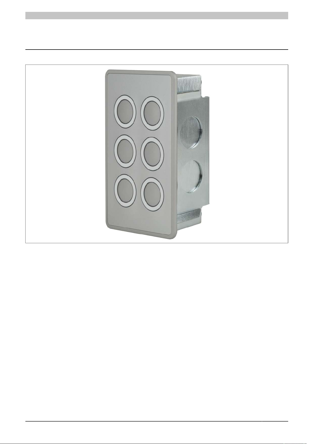
1 Views
Figure 1: 4XP0000.00-K64 - Oblique view

Views
4 Data sheet V1.40 4XP0000.00-K64
Figure 2: 4XP0000.00-K64 - Rear view
General information
Data sheet V1.40 4XP0000.00-K64 5
2 General information
Information:
B&R makes every effort to keep technical descriptions as current as possible. The latest version of
this technical description can be downloaded in PDF format from the B&R website at www.br-automa-
tion.com.
This user's manual is not intended for end customers! It is the responsibility of the machine manufac-
turer or system provider to provide the safety guidelines relevant to end customers in the operating
instructions for the end customer in the respective local language.
2.1 Order data
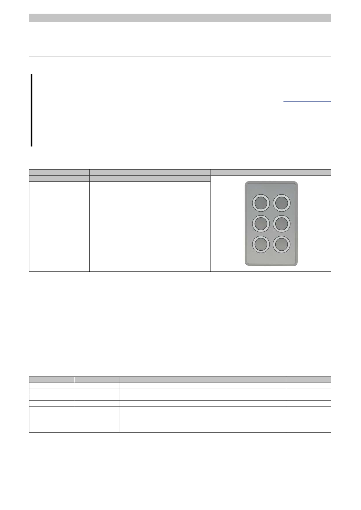
Model number Short description Figure
Keypad modules
4XP0000.00-K64 X2X keypad module, 6 B&R illuminated ring keys, 4-color
(green, yellow, red, white), IP65 protection, fast mounting using
single screw; connection made using M8/M12 circular connec-
tors
Table 1: 4XP0000.00-K64 - Order data
2.1.1 Description
4XP0000.00-K64 is a generally available add-on keypad with the following specifications:
•X2X keyboard
•Aluminum front with anodized surface
•6 B&R illuminated ring keys (green, yellow, white, red)
•Front and back: IP65 protection
•Fast mounting using a single screw
2.1.2 Version information
Version Date Comment Responsible
1.00 2011-09-16 First edition Anna Sigl
1.10 2012-03-21 Redesign Anna Sigl
1.20 2012-03-28 Pinout valid in Rev. C0 and later Anna Sigl
1.30 2013-01-11 Temperature specification Anna Sigl
1.40 2017-03-01 Updated data sheet.
•Updated information about power supply.
•Updated IP65 protection on front and back.
•Updated UL certification.
Nadine Koch
Table 2: Version information

General information
6 Data sheet V1.40 4XP0000.00-K64
2.2 Organization of safety notices
Safety notices in this manual are organized as follows:
Safety notice Description
Danger! Disregarding these safety guidelines and notices can be life-threatening.
Caution! Disregarding these safety guidelines and notices can result in severe injury or substantial damage to property.
Warning! Disregarding these safety guidelines and notices can result in injury or damage to property.
Information: This information is important for preventing errors.
Table 3: Organization of safety notices
2.3 Guidelines
E
European dimension standards apply to all dimension diagrams in this document.
All dimensions are specified in mm.
Unless otherwise specified, the following general tolerances apply:
Range of nominal sizes General tolerance according to
DIN ISO 2768 (medium)
Up to 6 mm ±0.1 mm
For 6 to 30 mm ±0.2 mm
For 30 to 120 mm ±0.3 mm
For 120 to 400 mm ±0.5 mm
For 400 to 1000 mm ±0.8 mm
Table 4: Range of nominal sizes

Complete system - Technical data
Data sheet V1.40 4XP0000.00-K64 7
3 Complete system - Technical data
3.1 Device interfaces
X2X OUT Power supply
X2X IN
Figure 3: 4XP0000.00-K64 - Device interfaces
3.1.1 X2X interface
X2X IN & OUT (M12 connectors)
X2X IN
Pin Description
1 X2X +
2 X2X
3 X2X ⊥
4 X2X \
X2X OUT
Pin Description
1 X2X +
2 X2X
3 X2X ⊥
4 X2X \
Table 5: X2X IN & OUT (M12 connectors)
Information:
The connector's pin assignments are designed so that standard X67 bus cables can be used.
3.1.2 Power supply
24 VDC voltage supply (M8 connector)
Power supply
Pin Description
1 24 V DC
2 24 V DC
3 GND
4 GND
Table 6: Power supply

Complete system - Technical data
8 Data sheet V1.40 4XP0000.00-K64
Information:
No bus power supply is necessary to operate the device (X2X Link power supply). The panel does not
have a power supply to provide bus voltage to additional devices.
The bus power supply is simply routed from the X2X IN connection to the X2X OUT connection and
can only supply additional bus stations using power supply modules with an X2X Link power supply.
3.1.3 Functional ground
A functional grounding clip is located next to the power supply connector. This grounding clip (functional ground)
must be connected to a central grounding point on the control cabinet using a 6.3 mm tab connector and the
shortest possible path with the least resistance possible (e.g. copper strip, at least 2.5 mm²).
Important!
The functional ground (pin 2) must be connected to ground (e.g. control cabinet) using the shortest
possible path. Using the largest possible conductor cross section on the power supply connector is
recommended.
Complete system - Technical data
Data sheet V1.40 4XP0000.00-K64 9
3.2 Technical data
Model number 4XP0000.00-K64
General information
Certification
CE Yes
UL cULus E115267
Industrial Control Equipment
Interfaces
X2X
Type X2X slave
Design 4-pin M12 connector
Internal bus supply Yes
Distance between 2 stations 100 m
Electrical isolation Yes
Keys
Illuminated ring keys 6x B&R illuminated ring keys
Illuminated ring keys
Color Red, green, yellow, white
Electrical characteristics
Nominal voltage 24 VDC
Power consumption Max. 8 watts
Voltage range 18 - 30 VDC
Current consumption Max. 320 mA (at nominal voltage)
Operating conditions
EN 60529 protection •Front: IP65
•Back: IP65
UL 50 protection Front: Type 4X indoor use only
Environmental conditions
Temperature
Operation 0 to +50°C
Storage -20 to +60°C
Transport -20 to +60°C
Relative humidity
Operation T ≤ 40°C: 5 to 85%, non-condensing
T > 40°C: < 75%, non-condensing
Storage T ≤ 40°C: 5 to 90%, non-condensing
T > 40°C: < 75%, non-condensing
Transport T ≤ 40°C: 5 to 90%, non-condensing
T > 40°C: < 75%, non-condensing
Elevation
Operation Max. 3000 m
Mechanical characteristics
Housing
Material Sheet metal, galvanized
Front
Frame Naturally anodized aluminum
Design RAL 9006
Panel overlay
Material Polyester
Gasket Flat gasket around display front
Dimensions
Width 77 mm
Height 123 mm
Depth 52.6 mm
Weight 450 g
Table 7: 4XP0000.00-K64 - Technical data

Complete system - Technical data
10 Data sheet V1.40 4XP0000.00-K64
3.3 Dimensions
Figure 4: 4XP0000.00-K64 - Dimensions
Table of contents
Popular Control Unit manuals by other brands

Festo
Festo Compact Performance CP-FB6-E Brief description

Elo TouchSystems
Elo TouchSystems DMS-SA19P-EXTME Quick installation guide

JS Automation
JS Automation MPC3034A user manual

JAUDT
JAUDT SW GII 6406 Series Translation of the original operating instructions

Spektrum
Spektrum Air Module System manual

BOC Edwards
BOC Edwards Q Series instruction manual

KHADAS
KHADAS BT Magic quick start

Etherma
Etherma eNEXHO-IL Assembly and operating instructions

PMFoundations
PMFoundations Attenuverter Assembly guide

GEA
GEA VARIVENT Operating instruction

Walther Systemtechnik
Walther Systemtechnik VMS-05 Assembly instructions

Altronix
Altronix LINQ8PD Installation and programming manual


