Berner BHR 150 User manual

Instruction manual
Berner Receiver BHR150
Article Number:
682, 685, 686, 688
Languages:
da, nl, en, fr, de, it, es, sv
BERNER_Instruction_manual_Berner_Receiver_BHR150_39917[PDF]_da.pdf 2016-11-10

Receiver User Guide 3...16
Empfänger Bedienungsanleitung 17...30
Récepteur Manuel d´utilisateur 31...44
Ricevitore Guida per l´uso 45...58
Receptor Guía del usuario 59...72
Ontvanger Gebruikershandleiding 73...86
Mottagare Operatörshandbok 87...100
Modtager Brugermanual 101...114
BHR 150 Receiver
User Guide
•
BHR 150
070993_HR 150 Aufbau.indd 1070993_HR 150 Aufbau.indd 1 27.08.2007 12:00:51 Uhr27.08.2007 12:00:51 Uhr

Q 103 741 Printed in Germany
070993_HR 150 Aufbau.indd 2070993_HR 150 Aufbau.indd 2 27.08.2007 12:00:56 Uhr27.08.2007 12:00:56 Uhr

3
Introduction
Thank you for choosing the BHR 150 receiver from Berner. The
BHR 150 is a battery-operated laser receiver that detects a rotating
laser beam and indicates its position relative to the beam using LEDs.
Before using the receiver, be sure to read this user guide carefully.
Included in it is information about setting up, using, and maintaining
the receiver. Also included in this manual are CAUTIONS and Notes.
Each of these words represents a level of danger or concern. A
CAUTION indicates a hazard or unsafe practice that could result in
minor injury or property damage. A Note indicates important
information unrelated to safety.
GB
070993_HR 150 Aufbau.indd 3070993_HR 150 Aufbau.indd 3 27.08.2007 12:00:57 Uhr27.08.2007 12:00:57 Uhr

4
Receiver
Features and Functions
1. Power/Audio Button—is a
multi-functional button that
turns on/off the receiver and
audio function.
2. Marking Notches (both
sides)—align with the
on-grade portion of the
photocell and are used to
mark elevation readings.
The marking notches are
50mm (2 inches) from the
top of the receiver.
3. LEDs (front and back)—
show the position of the
receiver relative to the laser beam (high, on-grade, or low), and
indicate power and low-battery status.
4. Level Bubble—is used to make sure that the receiver is level.
5. Photocell—detects the laser beam when it strikes the receiver.
6. Audio Port—is the opening the sound comes out of.
2
1
6
5
3
4
2
070993_HR 150 Aufbau.indd 4070993_HR 150 Aufbau.indd 4 27.08.2007 12:00:57 Uhr27.08.2007 12:00:57 Uhr

5
0 7. Clamp-Tab Recess—is the
area that the general-purpose
clamp’s release tab fits into.
0 8. Label—shows the serial
number and bar code.
0 9. Magnet—holds the receiver
on a wall molding, cross-T,
runner, etc.
10. Battery Housing—holds two
AA alkaline or rechargeable
batteries.
11. Battery Door—holds the
batteries securely in place.
12. Neck Cord Holder—allows
a neck cord to be attached to
the receiver.
11
12
89
10
7
070993_HR 150 Aufbau.indd 5070993_HR 150 Aufbau.indd 5 27.08.2007 12:00:58 Uhr27.08.2007 12:00:58 Uhr

6
How to Use the Receiver
Installing/Removing the Batteries
1. Release the battery door using your fingers, a coin, or a screwdriver.
Open the door.
2. Install/Remove the 2 AA batteries noting the positive (+) and
negative (–) diagram on the bottom of the battery housing.
3. Close the battery door and latch it shut.
070993_HR 150 Aufbau.indd 6070993_HR 150 Aufbau.indd 6 27.08.2007 12:00:59Uhr27.08.2007 12:00:59Uhr

7
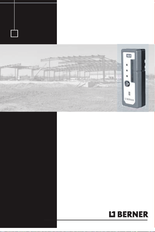
Learning the Receiver Functions
Turning On/Off the Receiver
1. Press the power/audio button to turn on the receiver.
Note: When the receiver is initially turned on, all LEDs and the
audio signal turn on for one second (diagnostic mode).
Note: The on-grade LED flashes once every two seconds to show
that the receiver is on.
2. Press and hold the power/audio button for two seconds to turn off
the receiver.
Note: When the receiver is being turned off, all the LEDs and the
audio signal quickly turn on for one second.
Selecting the Audio Function
The receiver always starts up with the audio mode active.
1. Press the power/audio button repeatedly to turn on/off the
audio function.
Note: If the audio function is on, the receiver beeps quickly when
the receiver is above the laser beam, slowly when below it, and
continuously when centered in the laser beam or on grade.
070993_HR 150 Aufbau.indd 7070993_HR 150 Aufbau.indd 7 27.08.2007 12:00:59Uhr27.08.2007 12:00:59Uhr

8
Using the Receiver with a Laser
1. Press the power/audio button to turn on the receiver.
2. Position the receiver so that its photocell faces the laser.
3. Move the receiver up/down until the LEDs show an on-grade
reading.
Note: The top/bottom red LEDs flash when the receiver is above or
below the laser beam. The green LED flashes when the receiver is
on grade.
ON
OFF
BERNER
High
On Grade
Low
Power/Audio Button
Audio Port
Low Battery
070993_HR 150 Aufbau.indd 8070993_HR 150 Aufbau.indd 8 27.08.2007 12:01:00 Uhr27.08.2007 12:01:00 Uhr

9
LED/Audio Information
LED/Audio Indication Function Audio Output
Green LED: flashes
once every two seconds Receiver is on N/A
Top red LED: flashing High Fast beeping tone
Green LED: flashing On-grade Continuous tone
Bottom red LED:
flashing Low Slow beeping tone
Both red LEDs:
flashing in sequence Low battery N/A
Speaker beep Audio on 3 beeps
Beam location Single beep
070993_HR 150 Aufbau.indd 9070993_HR 150 Aufbau.indd 927.08.2007 12:01:01 Uhr27.08.2007 12:01:01 Uhr

10
General-Purpose Clamp
The general-purpose clamp allows the receiver to be attached to a
survey rod or wooden pole.
Features and Functions
1. Release Tab—allows the receiver to be locked onto or released
from the general-purpose clamp.
2. Jaws—close/open so that the general-purpose clamp can be
attached to or released from a survey rod or wooden pole.
3. Reading Edge—aligns with the receiver’s on-grade marking
notches.
4. Jaws Screw—controls the closing/opening of the jaws.
4
2
1
3
070993_HR 150 Aufbau.indd 10070993_HR 150 Aufbau.indd 10 27.08.2007 12:01:01 Uhr27.08.2007 12:01:01 Uhr

11
Attaching the Receiver to the Survey Rod or
Wooden Pole
1. Slide the general purpose clamp
into the receiver until it “clicks”
into position.
2. Turn the jaws screw
counterclockwise to open the
clamp’s jaws.
3. Slide the survey rod or wooden
pole between the clamp’s jaws.
4. Turn the jaws screw clockwise
to hold the general-purpose
clamp securely in place.
070993_HR 150 Aufbau.indd 11070993_HR 150 Aufbau.indd 11 27.08.2007 12:01:02 Uhr27.08.2007 12:01:02 Uhr

12
Y
Receiver Specifications
LED Channels 3
Capture Height 50 mm (2 in.)
Acceptance Angle 90°
On-Grade Sensitivity Medium: 3.00 mm (1/8in.)
Power Source Two 1.5-V batteries (type LR6/AA)
Battery Life @ 20 °C (68 °F) Alkaline: 70+ hours
Low Battery Indicator Red LEDs flash in sequence
Automatic Shutoff 30 minutes after last laser detection
or push-button actuation
Spectral Sensitivity Operates with red visible and
infrared rotating lasers with
wavelength between 610 and
900 nm
Marking Notch 50 mm (2 in.) below top of
receiver, on both sides
Operating Temperature –20 °C to +50 °C
(–4 °F to +122 °F)
Storage Temperature –40 °C to +70 °C
(–40 °F to +158 °F)
Weight 0.3 kg (.75 lb)
Dimensions (H x W x D) 13.6 x 5.0 x 2.8 cm
(5.37 x 2.00 x 1.11 in.)
070993_HR 150 Aufbau.indd 12070993_HR 150 Aufbau.indd 12 27.08.2007 12:01:02 Uhr27.08.2007 12:01:02 Uhr

13
Y
Protecting the environment
Separate collection. This product must not be disposed of
with normal household waste.
Should you find one day that your BERNER product needs
replacement, or if it is of no further use to you, do not dispose of it
with household waste. Make this product available for
separate collection.
Separate collection of used products and packaging
allows materials to be recycled and used again. Re-use of
recycled materials helps prevent environmental pollution and reduces
the demand for raw materials.
Local regulations may provide for separate collection of electrical
products from the household, at municipal waste sites or by the
retailer when you purchase a new product.
BERNER provides a facility for the collection and recycling of
BERNER products once they have reached the end of their working
life. To take advantage of this service please return your product to
any authorized repair agent who will collect them on our behalf.
You can check the location of your nearest authorized repair agent
by contacting your local BERNER office at the address indicated
in this manual. Alternatively, a list of authorized BERNER repair
agents and full details of our after-sales service and contacts are
available on the Internet at www.Berner-Group.com.
070993_HR 150 Aufbau.indd 13070993_HR 150 Aufbau.indd 13 27.08.2007 12:01:03 Uhr27.08.2007 12:01:03 Uhr

14
EMC Declaration of Conformity
This receiver has been tested and found to comply with the limits for
a Class B digital device for radio noise for digital apparatus set out in
the Radio Interference Regulations of the Canadian Department of
Communication, and is pursuant to part 15 of the Federal
Communication Commission (FCC) rules. These limits are designed
to provide reasonable protection against harmful interference in a
residential installation. This receiver generates radio frequency. If it’s
not used in accordance with the instructions, it may cause harmful
interference to radio or television reception. Such interference can be
determined by turning the receiver off and on. You are encouraged to
try eliminating the interference by one or more of the following
measures:
• Reorient or relocate the receiving antenna.
• Increase the separation between the laser and the receiver.
For more information, consult your dealer or an experience radio/
television technician.
CAUTION: Changes or modifications to the receiver that are not
expressly approved by Berner could void authority to use the
equipment.
070993_HR 150 Aufbau.indd 14070993_HR 150 Aufbau.indd 14 27.08.2007 12:01:04 Uhr27.08.2007 12:01:04 Uhr

15
Declaration of Conformity
Application of 89/336/EEC
Council Directive(s):
Manufacturer’s Name: Albert Berner GmbH
Manufacturer’s Address: Berner Str. 6
74653 Künzelsau
Model Number: BHR 150
Conformance to Directive(s): EC Directive 89/336/EEC using
EN55022 and EN50082-1
Equipment Type/Environment: ITE/residential, commercial
& light industrial
Product Standards: Product meets the limit B
and methods of EN55022
Product meets the levels and
methods of IEC 801-2, 8 kV air,
4 kV contact IEC 801-3, 3 V/m 26
to 1000 MHz 80%, @ 1 kHz
070993_HR 150 Aufbau.indd 15070993_HR 150 Aufbau.indd 15 27.08.2007 12:01:05 Uhr27.08.2007 12:01:05 Uhr

16
Warranty
Berner warrants the receiver to be free of defects in material and
workmanship for a period of one year.
Berner or its authorized service center will repair or replace, at its
option, any defective part for which notice has been given during
the warranty period. If required, travel and per diem expenses to
and from the place where repairs are made will be charged to the
customer at the prevailing rates.
Customers should send the product to Berner or the nearest
authorized service center for warranty repairs, freight prepaid. In
countries with Berner subsidiary service centers, the repaired product
will be returned to the customer, freight prepaid.
Any evidence of negligent, abnormal use, accident, or any attempt to
repair the product by other than factory-authorized personnel using
Berner certified or recommended parts, automatically voids the
warranty.
The foregoing states the entire liability of Berner regarding
the purchase and use of its equipment. Berner will not be held
responsible for any consequential loss or damage of any kind.
This warranty is in lieu of all other warranties, except as set forth
above, including any implied warranty merchantability of fitness for a
particular purpose, are hereby disclaimed. This warranty is in lieu of
all other warranties, expressed or implied.
070993_HR 150 Aufbau.indd 16070993_HR 150 Aufbau.indd 16 27.08.2007 12:01:05 Uhr27.08.2007 12:01:05 Uhr

17
D
Einführung
Wir danken Ihnen, dass Sie sich für den Receiver BHR 150 von
Berner entschieden haben.
Das Modell BHR150 ist ein batteriebetriebener Handempfänger, der
den rotierenden Laserstrahl erfasst und seine Position relativ zum
Laserstrahl durch LEDs anzeigt.
Sie sollten diese Bedienungsanleitung sorgfältig lesen, bevor Sie
den Empfänger verwenden. Sie enthält Informationen über die
Inbetriebnahme, Verwendung und Wartung des Empfängers. In dieser
Bedienungsanleitung sind zudem Warnungen (ACHTUNG) und
Hinweise enthalten. Jeder dieser Begriffe nimmt Bezug auf ein
bestimmtes Gefahrenniveau. ACHTUNG weist auf eine Gefahr oder
unsichere Arbeitsweise hin, die zu geringfügigen Verletzungen oder
Sachschaden führen kann. Ein Hinweis enthält wichtige
Informationen, die nicht auf die Sicherheit bezogen sind.
070993_HR 150 Aufbau.indd 17070993_HR 150 Aufbau.indd 17 27.08.2007 12:01:06 Uhr27.08.2007 12:01:06 Uhr

18
Empfänger
Merkmale und Funktionen
1. Taste Ein/Aus/Tonsignal –
Multifunktionstaste, die den
Empfänger und das Tonsignal
ein- und ausschaltet.
2. Markierungskerben
(auf beiden Seiten des
Empfängers) – sind auf die
Anzeige “Auf Höhe” des
Laserstrahls ausgerichtet und
werden zur Übertragung
von Höhen verwendet.
Sie befinden sich 50 mm
unterhalb der Oberkante
des Empfängers.
3. LEDs (Front- und Rückseite) – zeigen die Position des
Empfängers relativ zum Laserstrahl an (zu hoch, “Auf Höhe“ oder
zu niedrig) und signalisieren die Einschaltkontrolle sowie eine
niedrige Batteriespannung.
4. Libelle – zum Überprüfen der horizontalen Ausrichtung des
Empfängers.
5. Empfangsfeld – zum Empfang des Laserstrahls
6. Tonsignalaustritt.
2
1
6
5
3
4
2
070993_HR 150 Aufbau.indd 18070993_HR 150 Aufbau.indd 18 27.08.2007 12:01:06 Uhr27.08.2007 12:01:06 Uhr

19
7. Aufnahme – rastet im
Empfängeradapter am
Freigabeknopf ein.
8. Aufkleber – zeigt die
Seriennummer und
den Barcode.
9. Magnet – hält den
Empfänger an Wandwinkeln
und anderen Deckenprofilen.
10. Batteriegehäuse – zur
Aufnahme von zwei 1,5 V
(AA) Alkali- Mignon- oder
Akkus-Batterien.
11. Batteriefachdeckel
12. Schnuraufnahme – zum
Anbringen der Halteschnur.
11
12
89
10
7
070993_HR 150 Aufbau.indd 19070993_HR 150 Aufbau.indd 1927.08.2007 12:01:07 Uhr27.08.2007 12:01:07 Uhr
This manual suits for next models
4
Table of contents
Languages:
Other Berner Receiver manuals