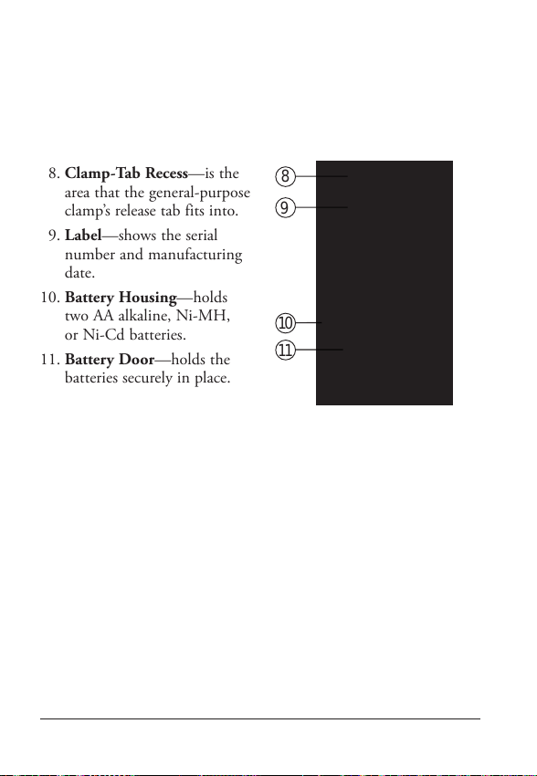
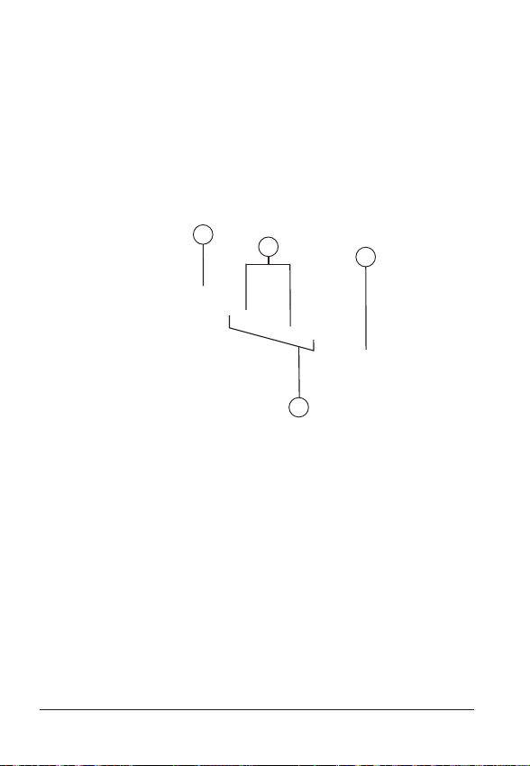
General-Purpose Clamp
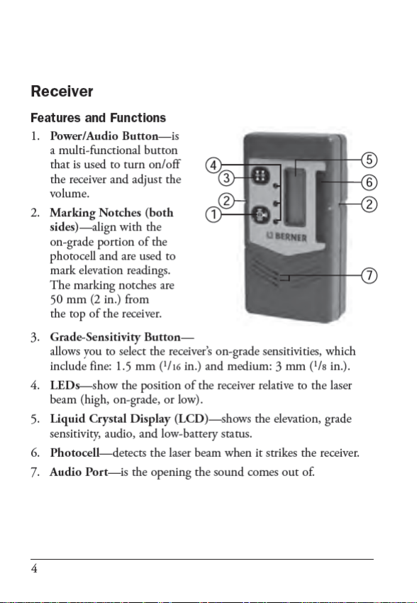
The general-purpose clamp allows the receiver to be attached to
a survey rod or wooden pole.
Features and Functions
Attaching the Receiver to the Survey Rod or Wooden Pole
Declaration of Conformity
Application of 89/336/EEC
Council Directive(s):
Manufacturer’s Name: Berner GmbH
Manufacturer’s Address: Berner Str.
74653 Künzelsau
Model Number: BHR 350
Conformance to Directive(s): EC Directive 89/336/EEC using
EN55022 and EN50082-1
Equipment Type/Environment: ITE/residential, commercial &
light industrial
Product Standards: Product meets the limit B and
methods of EN55022
Product meets the levels and
methods of IEC 801-2, 8 kV
air, 4 kV contact IEC 801-3, 3
V/m 26 to 1000 MHz 80%, @
1 kHz
Warranty
Berner warrants the receiver to be free of defects in material and
workmanship for a period of one year.
Berner or its authorized service center will repair or replace, at its
option, any defective part for which notice has been given during
the warranty period. If required, travel and per diem expenses to
and from the place where repairs are made will be charged to the
customer at the prevailing rates.
Customers should send the product to Berner or the nearest
authorized service center for warranty repairs, freight prepaid.
In countries with Berner subsidiary service centers, the repaired
product will be returned to the customer, freight prepaid.
Any evidence of negligent, abnormal use, accident, or any
attempt to repair the product by other than factory-authorized
personnel using Berner certified or recommended parts,
automatically voids the warranty.
The foregoing states the entire liability of Berner regarding
the purchase and use of its equipment. Berner will not be held
responsible for any consequential loss or damage of any kind.
This warranty is in lieu of all other warranties, except as set forth
above, including any implied warranty merchantability of fitness
for a particular purpose, are hereby disclaimed. This warranty is
in lieu of all other warranties, expressed or implied.
EMC Declaration of Conformity
This receiver has been tested and found to comply with the
limits for a Class B digital device for radio noise for digital
apparatus set out in the Radio Interference Regulations of the
Canadian Department of Communication, and is pursuant to
part 15 of the Federal Communication Commission (FCC)
rules. These limits are designed to provide reasonable protection
against harmful interference in a residential installation. This
receiver generates radio frequency. If it’s not used in accordance
with the instructions, it may cause harmful interference to radio
or television reception. Such interference can be determined
by turning the receiver off and on. You are encouraged to try
eliminating the interference by one or more of the following
measures:
• Reorient or relocate the receiving antenna.
• Increase the separation between the laser and the receiver.
For more information, consult your dealer or an experience
radio/television technician.
CAUTION: Changes or modifications to the receiver that are
not expressly approved by Trimble could void authority to use
the equipment.
Receiver Specifications
LCD/LED Channels 5
Capture Height 50 mm (2 in.)
Acceptance Angle 90°
On-Grade Sensitivity Fine: 1.50 mm (1/16 in.)
Medium: 3.00 mm (1/8in.)
Power Source Two 1.5-V batteries
(type LR6/AA)
Battery Life @ 20 °C (68 °F) Alkaline: 70 hours (LEDs off)
Battery Indicator LCD battery symbol
Automatic Shutoff 30 minutes after last laser detection or
push-button actuation
Spectral Sensitivity Operates with red visible and infrared
rotating lasers with wavelength
between 610 and 900 nm
Marking Notch 50 mm (2 in.) below top of
receiver, on both sides
Operating Temperature –20 °C to +50 °C (–4 °F to +122 °F)
Storage Temperature –40 °C to +70 °C (–40 °F to +158 °F)
Weight 0.28 kg (9.87 oz)
Dimensions (H x W x D) 13.5 cm x 7.2 cm x 2.7 cm
(5.32 in. x 2.83 in. x 1.06 in.)
1. Release Tab—allows the receiver to be locked onto or released
from the general-purpose clamp.
2. Jaws—close/open so that the general-purpose clamp can be
attached to or released from a survey rod or wooden pole.
3. Jaws Screw—controls the closing/opening of the jaws.
4. Reading Edge—aligns with the receiver’s on-grade marking
notches.
1. Slide the general-purpose
clamp into the receiver until
it “clicks” into position.
2. Turn the jaws screw
counterclockwise to open
the clamp’s jaws.
3. Slide the survey rod or
wooden pole between the
clamp’s jaws.
4. Turn the jaws screw
clockwise to hold the
general-purpose clamp
securely in place.
– 13 – – 14 –– 15 –
– 9 – – 10 –– 11 – – 12 –
A - Austria
Berner Gesellschaft m.b.H.
Industriezeile 36
A - 5280 Braunau
Tel. +43 77 22 80 00
Fax +43 77 22 80 01 86
berner@berner.co.at
www.berner.co.at
CH - Switzerland
Montagetechnik Berner AG
Kägenstrasse 8
CH - 4153 Reinach
Tel. +41 61 71 59 222
Fax +41 61 71 59 333
berner-ag@berner-ag.ch
www.berner-ag.ch
D - Germany
Albert Berner GmbH
Bernerstraße 4
D - 74653 Künzelsau
Tel. +49 79 40 12 10
Fax +49 79 40 12 13 00
info@berner.de
www.berner.de
E - Spain
Berner Montaje y Fijación S.L.
Polígono Industrial La Rosa VI
Calle Albert Berner, 2
E - 18330 Chauchina - GR
Tel. +34 958 06 02 00
Fax +34 902 11 31 90
berner-spain@berner.es
F - France
Berner, Z.I. Les Manteaux
F - 89331 St. Julien du Sault
Cedex
N° Azur
Tel. +33 810 23 76 37
Fax +33 810 57 95 79
(coût d’un appel local)
call-center@berner.fr
www.berner.fr
I - Italy
Berner S.p.A.
Via dell’Elettronica 15
I - 37139 Verona
Tel. +39 045 8 67 01 11
Fax +39 045 8 67 01 34
info@berner.it
2
13
4
Protecting the environment
Separate collection. This product must not be
disposed of with normal household waste.
Should you find one day that your BERNER product needs
replacement, or if it is of no further use to you, do not dispose of it
with household waste. Make this product available for
separate collection.Separate collection of used products
and packaging allows materials to be recycled and
used again. Re use of recycled materials helps prevent
environmental pollution and reduces the demand for raw
materials.
Local regulations may provide for separate collection of electrical
products from the household, at municipal waste sites or by the
retailer when you purchase a new product.
BERNER provides a facility for the collection and recycling
of BERNER products once they have reached the end of their
working life. To take advantage of this service please return your
product to any authorised repair agent who will collect them on
our behalf.
You can check the location of your nearest authorised repair
agent by contacting your local BERNER office at the address
indicated in this manual. Alternatively, a list of authorised
BERNER repair agents and full details of our after-sales service
and contacts are available on the Internet at
www.Berner-Group.com
6