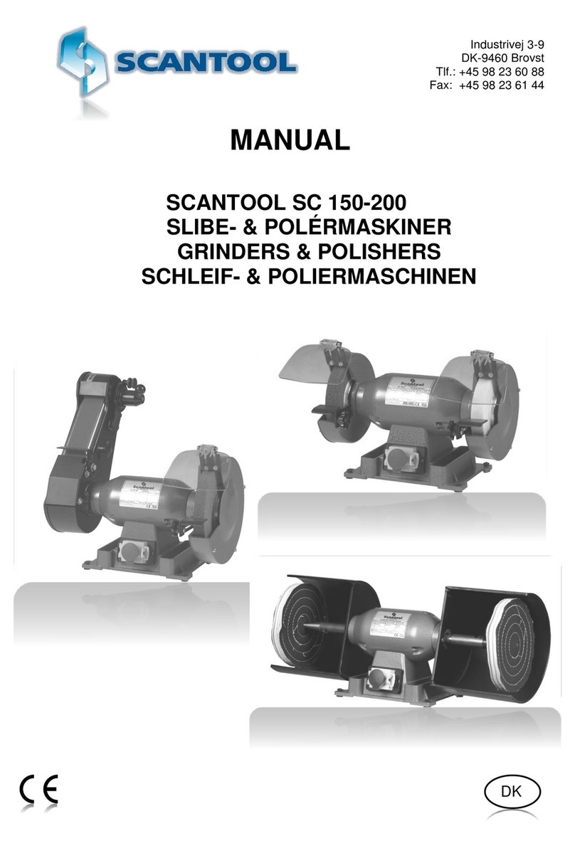
Scantool RB 75X User manual

Industrivej 3-9
DK-9460 Brovst
Tel.: 98 23 60 88
Fax: 98 23 61 44
15.01.16
Operating instructions for:
Pipe Notcher and Belt Grinder
RB/RBX 75-150

1
Introduction
The pipe notcher aggregate RB is developed in 2010 as a replacement for the pipe
notcher aggregate BR. The RB-aggregate can be utilized with many kinds of grinding
machines. This manual is based on the Scantool grinding machine.
EU Declaration of Conformity
Hereby declares that
SCANTOOL RB/RBX 75-150 is manufactured in accordance with the provisions of the
COUNCIL DIRECTIVE of 17. May 2006 (2006/42/EC) The Machinery Directive (order
no. 561 of 25 June 1994 with subsequent amendments)
2006/42/EC: Directive on machinery-safety
2004/108/EC: Directive on Electromagnetic Compatibility
2006/95/EC: Low Voltage Equipment Safety directive
Also on accordance with:
The council directive of 19 February 1973 (73/23/EEC) The Low Voltage Directive
with later amendments (order no. 797 of 30 August 1994)
The council directive of 3 May 1989 (89/336/EEC) The EMC Directive with later
amendments (order no. 796 of 5 December 1991 with subsequent amendments)
SCANTOOL A/S
Industrivej 3-9
9460 Brovst
Denmark
www.scantool-group.com
Ph.: 98 23 60 88
Fax.: 98 23 61 44

2
Table of contents
1. TRANSPORT AND HANDLING 3
2. INSTALLATION AND ADJUSTMENT 4
2.1 MOUNTING THE PIPE NOTCHING AGGREGATE,PURCHASED AS EXTRA EQUIPMENT 4
2.2 INSTALLING BELT GRINDER AND MOUNTING RB-AGGREGATE. 6
2.3 THOROUGH ADJUSTMENT OF THE SANDING BELT. 11
3. USERS GUIDE 11
3.1 OPERATION 12
3.2 SAFETY RULES FOR STATIONARY TOOL MACHINES. 13
3.3 MAINTENANCE 15
3.4 ROLL HOLDER –LOCATION OF CONTACT DISCS 15
3.5 ADJUSTMENT OF THE PIPE HOLDER’S HEIGHT COMPARED TO THE ROLLER 16
3.6 ANGLE OF PIPE NOTCHING 17
3.7 SIDE ADJUSTMENT 18
3.8 PLACEMENT OF ITEM 18
4. SPARE PARTS 19
4.1BELT GRINDER WITH NO EXHAUST 19
4.2 BELT GRINDER WITH EXHAUST 21
4.3 RB AGGREGATE 23
4.4 CONTACT DISCS 25
4.5 SANDING BELTS 27
5. TECHNICAL DATA 29
5.1 TECHNICAL SPECIFICATIONS 29
5.2 DIMENSIONS 30
5.3 CIRCUIT DIAGRAMS 31
5.4 PRESSURE DIAGRAM 35
5.5 WARRANTY 35

3
1. Transport and handling
The products can swiftly be transported on the pallet they arrive on. Remove the
packaging.
When you receive grinder and RB-aggregate as a set.
SCANTOOL belt grinder and RB-aggregate comes installed on a pallet wrapped in
protective packaging with the following dimensions: 1200 x 800 mm. The roll
holder, that is a part of the aggregate is mounted on the grinder.
When you receive the RB-aggregate as a extra equipment for you grinder.
An RB-aggregate is delivered mounted to a pallet. You can see the aggregate below.
Fig.: 1.1 Complete pipe notching attachment
Remove the packaging and the fastening screws in the pallet and lift the belt
grinder and the aggregate of the pallet.

4
2. Installation and adjustment
The installation of the products must take place on an evenly flat surface. The grinder
should be fastened into the floor.
2.1 Mounting the Pipe notching aggregate, purchased as extra
equipment
This section concerns how the roll holder of the aggregate is mounted to a grinder. If you
have received the RB-aggregate and grinder as a set, the roll holder is allready in place
grinder
If you have purchased the RB-aggregate as an extra equipment for your grinder, and the
grinder i produced before around 2011, initially two threaded holes must be established in
the grinders Fork for contact weel and then the role holder is mount with the new
grindingbelt. The procedure is described below.
2.1.a Dismantling
Remove the sparkbox (F) and holder of the grinding facility holder (B) from the grinder.
Figur 2.1.1 Parts of a grinder.
2.1.b Establishment of threaded holes.
Establish as accurately as possible two M6 threaded holes in the belt grinder's fork for
contact weel. Belt grinders manufactured before around 2011 do not have these holes.
See grinder split draft position 23 and place the holes as according to the drawing in figur
2.1.2.

5
Figur 2.1.2 Dimensions for establishing of thread holes.
2.1.c Mounting the Fork Bracket
The fork bracket is tightened with two screws, see below. Make sure the underside of the
little plate seen on the upper fork bracket is level with the top of the fork of the contact
wheel (see picture below). You can hold a finger on top of the support plate while fastening
the bracket.
Fig. 2.1.3 The fork bracket is mounted on the grinder.
2.1.d Mounting of roll holder.
Roll holder and justification part is mounted as seen below, left on fig. 2.1.4. Fasten the
justification part that is situated to the right by the M6-screw. Mantle then the grinding belt.
(grinding belts are given in sec. 5.1: Technical Data).
Check that the roll holder sits straight by measuring the distance between the cross bar of
the roll holder and the shaft of the contact weel in both sides. In case it is the right contact
disc that sits in the roll holder (corresponding to the thickness of the pipe to be notched)
you can just go ahead. Otherwise change contact disc. See section 3.4 for placement of
contact disc.

6
Fig. 2.1.4 Roll holder and justification part i mounted.
2.2 Installing Belt Grinder and Mounting RB-Aggregate.
In the following you will need the tools below:
Spanners 2x17mm
Spanners 1x13mm
Spanners 1x10mm
1x3mm Hex key
1x5mm Hex key
Spirit level
2.2.a Installing the belt grinder.
The belt grinder should be installed at a level, smooth, solid surface. Attach it to the floor
and tilt it to horizontal position.
2.2.b Dismantling of two bolts.
Dismantle the two screws M10x16 on the right side of the belt grinder. See fig. 2.2.2.
2.2.c Connect the bodies of belt grinder and aggregate.
On the bottom of the belt grinder body is found one or two slotted holes. This is the belt
grinders original holes for mounting the spark box. The spark box is dismantled.
On the draft below the back side of the aggregate is seen to the right and the front of the
belt grinder is seen to the left. The draft below only shows one slotted hole as with a 75
model, where as 150-models have two slotted holes. The arrow starts at the assembling
part which is specially designed to connect belt grinder and RB-aggregate. The
assembling part has two threaded rods for a 150 RB-model as it follows.
Slide the front end of the aggregate in around the beltgrinder as the arrow shows on the
figure below. Push the aggregate in so the bottom of the aggregate goes under the bottom
of the belt grinder front and so the assembling part goes into the slot.

7
Figur 2.2.1 Samlingsgevindstykket forener de to kroppe.
The assembling part should go right to the bottom of the slot in the belt grinder. Tighten
the nut underneath loosely so it is possible to make further adjustment.

8
2.2.d Mounting two bolts on the right side.
Then mount the two bolts M10x16 on the right side (see the figure below at the arrows),
they are tightened loosely with possibility of further adjustment.
Fig.: 2.2.2 Two screws M10x16 on the right
Belt grinder and aggregate are now positioned horizontally at the top by help of the Spirit
level. The belt grinder can be tilted and the aggregates foot has 4 screws under making it
possible to stabilize and adjust the height. Tighten the nut(s) on the assembling part at the
bottom of the aggregate. Tighten them well! The two bolts on the right side are also
tightened.

9
2.2.e Adding the right and left support brackets.
Fig.: 2.2.3 Suppport Brackets are mounted
The support brackets (left: S2 and right:S1) sits upside down during the shipping. When
mounted they counteract a vertical movement of the roll holder. Dismantle a screw and
turn them upwards (see figure 2.2.3) with the split inside the oval hole at the top. Tighten
left and right support bracket (S2 and S1) tightly with the two M6x12 Allen Screws.
2.2.f Dismantling and attaching of the housing.
Fig.: 2.2.4 The housing is dismantled by loosening of the two screws.
On the draft above the housing is seen in grey. The housing can swiftly be taken off and
on by loosening and tightening the Allen Screw M6x12 at the bottom of each side of the
housing. The left screw is seen on the draft.

10
2.2.g The belt grinder is prepared
This section concerns users who accessed the belt grinder and aggregate as a set. If you
have already a prepared belt grinder you can jump to the next section 2.2.h.
The belt grinder is in standard delivered equipped with a speed motor with motor brake,
switches (X) with overload relays, zero voltage poles, and coupled to the desired voltage.
! The electrical connection must be performed by a licensed electrician. It should be
verified that the motor (and possibly the ventilator) has the correct rotation (see the arrow
on the motor).
2.2.h Preparation before use.
Before use, eye protection, suction hoses and dust bag should be mounted. Clamps for
installing the suction hose is found in the dust bag. Eye protection (A) should be mounted
in the eye protection bracket (see Fig.: 2.2.1). Check that the aggregate does not touch the
belt.
Fig. 2.2.5 Belt grinder with attached RB aggregate 150
2.2.i Handle adjustment of the belt straight way
The following justification is swiftly done with handle D in case of receiving the belt grinder
and RB aggregate as a set. The other way of adjusting belt straight way was handled at
the production site. Therefore it is possible to start the grinder and control that it is running
straight and stable as follows:
1. Turn the contact wheel (E) by hand and adjust the belt with the handle (D) until it
runs straight.
2. Start the engine carefully and fine tune again with the handle.
E
A
D
X

11
If the handle can not get the belt to run straight it is necessary to make a different
adjustment. This may, for example, be the case if you have received the RB unit as extra
utils. of the tape straight way out in the following section 2.3.
2.3 Thorough adjustment of the sanding belt.
If the belt starts running unevenly and the handle (D) on fig. 2.2.5 cannot make the belt run
straight it is necessary to make an adjustment with the adjustment part. Via the adjustment
part seen on fig. 2.3.1 you can change the angle of the contact disc which is relevant for
the sanding belt run.
Fig 2.3.1 The adjustment part can adjust the grinding belt.
2.3.a Get ready to adjust
Loosen the right and left support brackets and turn the handle D so it is approx. midway
between the two extreme positions. Check that the machine stands stable and that both
bodies are horizontal. The nuts B1 and B2 are shown in Fig. 2.3.1 should be free and
detached as the drawing.
2.3.b Adjustment with adjustment part
Turn unbracobolt w/spring in adjustment part labeled "A" fig. 2.3.1. This will move the
thread in adjustment part up or down and this will result in the tape runs either right or left.
If you turn the bolt counter clockwise it influences the band to the left and turn the bolt
clockwise influences the band to the right. Run the belt forward by hand to see the result of
your adjustment. When the tape runs just it is adjusted. Then the machine can be started
you can fine tune with the same bolt while it is running.
2.3.c Adjustment of grinding belt.
Check that the belt runs level on the roll. First through manual operation. If the belt runs to
one side, it can be adjusted using an unbraco-bolt w/spring (pos. 34 and 43). Then the
machine can be started at low speed and can be fine tuned with the same bolt. The
adjustment is locked by tightening the two nuts (pos. 32) on the adjustment part. The
rough adjustment should only be done occasionally. To ensure that the adjustment does
not shift, the supporting brackets are now fastened (Nos. 12 and 13 (RB)).
For normal operation, the belt is fine-tuned by using adjustment lever D as usual on the
belt grinder. (see drawing below)
3. Users guide
Here, the two 2xM6 have been
established.

12
3.1 Operation
After installing and connecting the above mentioned, the pipe notcher is ready for use.
Pipe notching can be done at the contact disc and belt grinding on the level grinding table
by opening the lid. A grinding is increased if you start with a light grinding
pressure.

13
3.2 Safety rules for stationary tool machines.
Follow them to achieve best results and full benefit from your new machine.
The good craftsman respects
the tools with which he works.
He knows they represent years
of constantly improved design.
He also knows that they are
dangerous if misused.
This is the theme of a new safe-
use program for stationary
power tools. The safety rules
are based on approved
practices in industrial and home
shops
1.
carefully. Learn its applications and limitations, as
well as the specific
potential hazards
peculiar to this tool.
2. Keep guard in place
and in working order.
3. Ground all tools. If tool is equipped with three-
prong plug, it should be plugged into a three-hole
electrical receptacle. If an adapter is used to
accomodate a two-
prong receptacle, the
adapter wire must be
attached to a known
ground. Never
remove the third
prong.
4. Remove adjusting
keys and wrenches.
Form habit of checking to
see that keys and
adjusting wrenches is
removed before turning it
on.
5. Cluttered areas and benches invite accidents.
6. Avoid dangerous
power tools in damp or wet
locations or expose them
to rain. Keep your work
area well lighted.
6. Keep children away.
All visitors should be
kept in a safe distance
from work area.
8. Make workshop
kidproof with
padlocks, master
switches, or by
removing starter
keys.
9.
safer at the rate for
which it was designed.
.
10. Use right tool.
attachment to do
a job it was not
11. Wear proper apparel. Wear no loose clothing,
gloves, neckties, rings, bracelets, or other jewelry
which may get caught in moving parts. Non-slip
footwear is recommended. Wear protective hair

14
designed for.
covering to contain long
hair.
12. Always use safety
glasses. Also use face or
dust mask if cutting
operation is dusty.
Everyday eyeglasses only
have impact resistant
lenses. They are NOT
safety glasses.
13. Secure works. Use
clamps or vise to hold
safer than using your
hands and it frees both
hands to operate tool.
14.
overreach.
Keep
proper
footing and
balance at
all times.
15. Maintain tools with care. Keep tools sharp and
clean for best and safest
performance. Follow
instructions for lubricating
and changing accessories.
16. Disconnect tools before
servicing and when changing
accessories such as grinding
wheels, polishing mops,
grinding belts, blades, bits,
cutters, etc.
17. Reduce the risk of
unintentional starting.
Make sure switch is in off
position before plugging
in.
18.
manual for recommended accessories. Use of
improper accessories may cause risk of injury to
persons.

15
3.3 Maintenance
Clean the suction ducts regularly. The dust bag is emptied after use. Replace the grinding
surface on the level grinding table as needed.
For belt replacements, the pressure is taken off the belt by turning the handle (D) on fig.
2.2.5 counterclockwise. The housing (see fig. 2.2.4) is disassembled and the worn belt is
removed. Put a new belt on and verify that the direction of the arrows on the back of the
belt, are equivalent to the direction of the rotation. The handle (D) is turned back clockwise
until the belt is tightened. And then the housing is assembled again.
Check that the belt runs in the middle by turning the belt around with your hand and adjust
inwards if necessary.
3.4 Roll holder –location of contact discs
The distance between belt grinder and contact weel must be changed when you wish to
grind another pipe dimension.
As an illustrative indication, we have made a drawing of t
positions, corresponding to different roll sizes.
Indication of Contact disc position.
On the side of the aggregate you will find a sticker with the above table.
Position
Contact disc(mm)
Contact disc (inch)
1-3
ø17-27
Ø0.67 - 1.1
2-4
ø27-37
Ø 1.1 - 1.5
3-5
ø37-47
Ø 1.5 1.9
4-6
ø47-57
Ø 1.9 2.3
5-7
ø57-67
Ø 2.3 2.6
6-8
ø67-80
Ø 2.6 3.1
7-9
ø80-95
Ø 3.1 3.7
8-10
ø90-100
Ø 3.5 4
9-11
ø95-100
Ø 3.7 - 4

16
3.5 Adjustment of the pipe holder’s height compared to the roller
It is important that the contact disc and the pipe holder are parallel and at the correct
height.
3.5.a Contact disc and Pipe Holder is made Parallel
The distance between the pipe holder table surface and the top of the roll in the right and
left side should be the same (=parallel).
Fig.:3.5.1 Height difference between Contact disc and pipe holder table is measured.
If there is a measurable height difference this should be adjusted. On fig. 3.5.2 the pipe
holder is seen. The lower part lies in reality inside the body and under the body you will
find the shown bolts and nuts protuding out.
Figur 3.5.2 The Pipe Holder is seen from below- the body is invisible.
First you loosen the nuts that the arrows point to. The table lies now loose in the body of
the aggregate on top of the 4 bolts w/nuts(V1, V2, H1, H2) that is seen on fig. 3.5.2. You
must now rotate in pairs on either the two nuts on the left side or the two nuts on the right
side.
By turning the nuts V1 and V2 one circuit downwards and after that the bolt one circuit up
the table will move one mm upwards in the left side and similarly for H1 and H2. So

17
when you finish making the pipe holder parallel to the contact disc you fasten the two nuts
that the arrow points to again.
Height adjustment of pipe holder to the middle of the roll holder is done through a similar
adjustment of the 4 screws mentioned above. Now you have to turn all 4 nuts at once. One
full turn equals a 1 mm adjustment.
3.6 Angle of Pipe Notching
The grip (pos. 41 on the spare part list of the aggregate) is loosened and rotated to the
desired degree, after which it is tightened, and the subject is placed in the vice and
fastened.
Fig. 3.6 shows a pipe and sanding belt from above. A RB pipe grinder can grind at a
maximum angle. The width of the band, however, limit the scope. An RB75 is limited
for pipe sizes over 35 mm, while an RB150 is limited for pipe sizes over 72 mm.
You can interpolate in according to the table in Fig. 3.6.
L: Belt Width; Ø: Width of the item/pipe
Vmax: Maximum Angle possible.
Ø(mm)
V(max)
L=75 mm
(RB75)
L=150
(RB150)
17
60
60
35
60
60
40
55
60
50
44
60
60
31
60
65
22
60
70
0
60
75
0
59
80
-
57
90
-
52
100
-
46
110
-
41
120
-
34
130
-
26
140
-
15
145
-
0
150
-
0
Fig 3.6 Maximum Angles of Pipe Notching at Different Pipe Dimensions.

18
3.7 Side adjustment
Verify that the subject hits approximately in the centre of the contact discer and belt, if not,
make a side adjustment with the help of the hand wheel (pos 2 on the spare parts list of
the aggregate).
3.8 Placement of item
The table is placed in the rear position and the item/pipe is placed in the vice and led
forward to approximately 10-50 mm / 0.4- (depending on diameter) from the contact
discer and the item is fastened.
You can now use the pipe notcher on the unit.

19
4. Spare parts
When ordering spare parts, the production and serial number must be disclosed.
4.1Belt grinder with no exhaust
Fig.:4.1 Split drawing of belt grinder with no exhaust
This manual suits for next models
8
Table of contents
Other Scantool Grinder manuals
Popular Grinder manuals by other brands

Metabo HPT
Metabo HPT G13SC2 Safety instructions and instruction manual

HIKOKI
HIKOKI G 18SE4 Handling instructions

Extol Industrial
Extol Industrial 8791840 Translation of the original user manual

Makita
Makita GA4590 instruction manual

Pecol
Pecol RB2600PROHP-230 manual

SUHNER
SUHNER LLG 4 Technical document

Bavaria
Bavaria BAG 115 Original operating instructions

Hitachi
Hitachi G 23UB2 Handling instructions

Zoeller
Zoeller 71 HD Series owner's manual

King Canada
King Canada 8208K instruction manual

Florida Pneumatic
Florida Pneumatic Universal Tool UT8737 General Safety Information & Replacement Parts

Hilti
Hilti AG 180-20 D manual