BERNSTEIN SRF DI Series User manual

BERNSTEIN AG . Hans-Bernstein-Straße 1 . 32457 Porta Westfalica . www.bernstein.eu Seite 1 von 20
0800000860, 0206-18 / Issue date: 2018-04-17
Betriebs- und Montageanleitung / Installation and Operating Instructions / Instructions de service et de montage
BERNSTEIN AG . Hans-Bernstein-Straße 1 . 32457 Porta Westfalica . www.bernstein.eu BERNSTEIN-Dok.: 0800000860 / Stand: 1 / 2018-04-17 / 0206-18 Seite 1 von 20
www.bernstein.eu
Betriebs- und Montageanleitung/
Installation and Operating Instructions/
Instructions de service et de montage
Contact
International Headquarters
BERNSTEIN AG
Hans-Bernstein-Straße 1
32457 Porta Westfalica
Fon+49 571 793-0
Fax +49 571 793-555
[email protected]ein.eu
www.bernstein.eu
China
BERNSTEIN Safe Solutions
(Taicang) Co., Ltd.
Fon+86 512 81608180
Fax +86 512 81608181
info@bernstein-safesolutions.cn
Hungary
BERNSTEIN Kft.
Fon+36 1 4342295
Fax +36 1 4342299
Denmark
BERNSTEIN A/S
Fon+45 7020 0522
Fax +45 7020 0177
France
BERNSTEIN S.A.R.L.
Fon+33 1 64 66 32 50
Fax +33 1 64 66 10 02
info@fr.bernstein.eu
Italy
BERNSTEIN S.r.l.
Fon+39 035 4549037
Fax +39 035 4549647
United Kingdom
BERNSTEIN Ltd
Fon+44 1922 744999
Fax +44 1922 457555
Austria
BERNSTEIN GmbH
Fon+43 2256 62070-0
Fax +43 2256 62618
Switzerland
BERNSTEIN (Schweiz) AG
Fon+41 44 775 71-71
Fax +41 44 775 71-72
SRF Diagnosegeräte /
SRF diagnostic devices /
Appareils de diagnostic SRF
SRF DI...
Betriebs- und Montageanleitung / Installation and Operating Instructions / Instructions de service et de montage
BERNSTEIN AG . Hans-Bernstein-Straße 1. 32457 Porta Westfalica . www.bernstein.eu BERNSTEIN-Dok.: 0800000860 / Stand: 1 / 2018-04-17 / 0206-18 Seite 1 von 20

BERNSTEIN AG . Hans-Bernstein-Straße 1. 32457 Porta Westfalica . www.bernstein.eu Seite 2 von 20
Betriebs- und Montageanleitung / Installation and Operating Instructions / Instructions de service et de montage
BERNSTEIN AG . Hans-Bernstein-Straße 1. 32457 Porta Westfalica . www.bernstein.eu BERNSTEIN-Dok.: 0800000860 / Stand: 1 / 2018-04-17 / 0206-18 Seite 2 von 20
Bestimmungsgemäßer Gebrauch/
Intended use/
Utilisation conforme à la destination
1
Anwendung/
Application/
Application
2
D – Deutsch GB – English FR – Français
Die SRF Diagnosegeräte der BERNSTEIN AG dienen als
Interface, um die seriellen Daten der SRF (Daisy Chain
Diagnose DCD) über diverse Schnittstellen (IO-Link, NFC, USB
und PNP-Ausgang) dem Anwender zur Verfügung zu stellen.
!Die SRF Diagnosegeräte sind keine Sicherheitsgeräte. Die
Daten und Signale aus diesen Geräten sind nicht
sicherheitsrelevant.
The SRF diagnostic devices from BERNSTEIN AG act as an
interface to provide the user with serial data for the SRF (Daisy
Chain Diagnostic DCD) across various interfaces (IO-Link, NFC,
USB and PNP output).
!SRF diagnostic devices are not safety devices. The data and
signals from these devices are not relevant to safety.
Les appareils de diagnostic de BERNSTEIN AG servent
d’interface pour la mise à disposition de l’utilisateur des
données sérielles de SRF (Daisy Chain Diagnose DCD) via
différentes interfaces (sorties IO-Link, NFC, USB et PNP).
!Les appareils de diagnostic SRF ne sont pas des appareils de
sécurité. Les données et les signaux provenant de ces appareils
ne sont pas critiques pour la sécurité.
Um die Daten aller Sensoren mit dem Diagnosegerät
empfangen zu können, wird es zwischen dem letzten Sensor
einer SRF-Kette und der sicheren Auswertung geschaltet
(Bild 1).
To be able to receive data from all sensors with this diagnostic
device, it is wired in between the last sensor on an SRF chain
and the secure evaluation device (Fig. 1).
Pour recevoir les données de tous les détecteurs avec les
appareils de diagnostic, une commutation est effectuée entre
le dernier détecteur d’une chaîne SRF et l’évaluation en toute
sécurité (Fig. 1).
Jedes Auswertegerät verfügt über eine USB, NFC und IO-Link
Schnittstelle.
Every evaluation device has a USB, NFC and IO-Link port. Chaque appareil d’évaluation dispose d’une interface USB, NFC
et IO-Link.
Bild 1
Fig. 1

BERNSTEIN AG . Hans-Bernstein-Straße 1 . 32457 Porta Westfalica . www.bernstein.eu Seite 3 von 20
Betriebs- und Montageanleitung / Installation and Operating Instructions / Instructions de service et de montage
BERNSTEIN AG . Hans-Bernstein-Straße 1 . 32457 Porta Westfalica . www.bernstein.eu BERNSTEIN-Dok.: 0800000860 / Stand: 1 / 2018-04-17 / 0206-18 Seite 3 von 20
Das SRF DI6-C-0/1-T kann bis zu 6 SRF-Ketten mit maximal je 32
SRF verarbeiten. Die Diagnosedaten jeder Sicherheitskette bzw.
von jedem SRF aus jeder Kette können über die Schnittstellen
abgerufen werden.
Die Darstellung in Bild 2 zeigt Beispielhaft ein System mit 3
Sicherheitskreisen.
The SRF DI6-C-0/1-T can process up to 6 SRF chains, each with a
maximum of 32 SRFs. The diagnostic data on each safety chain
and/or of every SRF from every chain, can be called up via these
ports.
The illustration in Fig. 2 shows an example of a system with 3
safety circuits.
Le SRF DI6-C-0/1-T peut traiter jusqu’à 6 chaînes SRF avec
chacune 32 SRF au maximum. Les données de diagnostic de
chaque chaîne de sécurité ou de chaque SRF de chaque chaîne
peuvent être appelées via les interfaces.
L‘illustration de la Fig. 2 montre un exemple d‘un système avec
3 circuits de sécurité.
Bild 2
Fig. 2

BERNSTEIN AG . Hans-Bernstein-Straße 1. 32457 Porta Westfalica . www.bernstein.eu Seite 4 von 20
Betriebs- und Montageanleitung / Installation and Operating Instructions / Instructions de service et de montage
BERNSTEIN AG . Hans-Bernstein-Straße 1. 32457 Porta Westfalica . www.bernstein.eu BERNSTEIN-Dok.: 0800000860 / Stand: 1 / 2018-04-17 / 0206-18 Seite 4 von 20
Das Diagnosegerät bietet eine IO-Link Schnittstelle zum
busunabhängigen Einlesen der Diagnosedaten in eine
Steuerung.
!Die Diagnosedaten sind nicht sicherheitsrelevant.
The diagnostic device offers an IO-Link interface for
bus-independent scanning of diagnostic data into a
controller.
!The diagnostic data is not relevant to safety.
L’appareil de diagnostic dispose d’une interface IO-Link
permettant une lecture indépendante du bus des données
de diagnostic d’une commande.
!Les données de diagnostic ne sont pas critiques pour la
sécurité.
Funktion / Schnittstellen/
Function / Interfaces/
Fonction / Interfaces
3
IO-Link Slave IO-Link Slave IO-Link esclave
24 V
+
IO-Link 24 V
IO-Link CQ
-
L+
COM
- 3
4
1
IO-Link
Master
SRF DI
Bild 3
Fig. 3
Die Datenstruktur im IO-Link Protokoll entnehmen Sie
bitte dem Dokument IO-Link-Konfigurationsbeschreibung
0800000857.
Die zur Konfiguration notwendige IODD und die IO-Link-
Konfigurationsbeschreibung finden Sie auf der BERNSTEIN AG
Website (www.bernstein.eu).
For details of the data structure in the IO-Link protocol, please
refer to the IO-Link configuration description document,
reference number 0800000857.
The IODD needed for configuration and the IO-Link
configuration description can be found on the BERNSTEIN AG
website (www.bernstein.eu).
Vous trouverez la structure des données dans le protocole
IO-Link du document Description de la configuration IO-Link
0800000857.
Vous trouverez l’IODD nécessaire pour la configuration et la
description de la configuration IO-Link sur le site Internet de
BERNSTEIN AG (www.bernstein.eu).
Anschluss an einen IO-Link Master/
Connection to an IO-Link Master/
Raccordement à un IO-Link maître

BERNSTEIN AG . Hans-Bernstein-Straße 1 . 32457 Porta Westfalica . www.bernstein.eu Seite 5 von 20
Betriebs- und Montageanleitung / Installation and Operating Instructions / Instructions de service et de montage
BERNSTEIN AG . Hans-Bernstein-Straße 1 . 32457 Porta Westfalica . www.bernstein.eu BERNSTEIN-Dok.: 0800000860 / Stand: 1 / 2018-04-17 / 0206-18 Seite 5 von 20
USB USB USB
Das Diagnosegerät bietet eine Schnittstelle zur Anzeige der
Sensorinformationen auf dem PC / Laptop.
Der PC / Laptop muss mittels eines USB A auf USB Mini B
Steckers verbunden werden.
Die notwendige PC-Software finden Sie auf der BERNSTEIN AG
Website (www.bernstein.eu).
Die Dokumentation der Software 0800000858 finden Sie auf
der BERNSTEIN AG Website (www.bernstein.eu).
The diagnostics device provides an interface for displaying
sensor information on the PC / laptop.
The PC / laptop must be connected to a USB Mini B connector
by means of a USB A connector.
You can find the PC software you require on the
BERNSTEIN AG website (www.bernstein.eu).
You can find software documentation 0800000858 on the
BERNSTEIN AG website (www.bernstein.eu).
L’appareil de diagnostic dispose d’une interface pour l’affichage
des informations des détecteurs sur un PC/ordinateur portable.
Le PC/l’ordinateur portable doit être raccordé au connecteur
USB Mini B via un connecteur USB A.
Vous trouverez les logiciels pour PC nécessaires sur le site
Internet de BERNSTEIN AG (www.bernstein.eu).
Vous trouverez la documentation relative au logiciel 0800000858
sur le site Internet de BERNSTEIN AG (www.bernstein.eu).
NFC NFC NFC
Das Diagnosegerät bietet eine Schnittstelle zur Übertragung
der Diagnosedaten auf ein Android Smartphone mit NFC
Schnittstelle.
Das Smartphone muss dabei über den mit
gekennzeichneten Bereich gehalten werden.
Die benötigte App kann im Appstore oder über die
BERNSTEIN AG Website (www.bernstein.eu) heruntergeladen
werden.
Die Dokumentation der App 0800000859 finden Sie auf der
BERNSTEIN AG Website (www.bernstein.eu).
Folgende Daten werden über diese Schnittstellen
bereitgestellt:
The diagnostics device provides an interface for transmitting
the diagnostics data to an Android smartphone with an NFC
port.
For this, the smartphone must be held by the area marked
with .
The app required can be obtained from the Appstore or
can be downloaded from the BERNSTEIN AG website
(www.bernstein.eu).
You will find documentation for app 0800000859 on the
BERNSTEIN AG website (www.bernstein.eu).
The following data is provided via these interfaces:
L’appareil de diagnostic dispose d’une interface pour la
transmission des données de diagnostic sur un smartphone
Android avec interface NFC.
Le smartphone doit pour cela être maintenu sur la zone
indiquée par .
L’application requise peut être téléchargée sur l’Appstore ou
sur le site Internet de BERNSTEIN AG (www.bernstein.eu).
Vous trouverez la documentation relative à l’application
0800000859 sur le site Internet de BERNSTEIN AG
(www.bernstein.eu).
Les données suivantes sont disponibles via ces interfaces :

BERNSTEIN AG . Hans-Bernstein-Straße 1. 32457 Porta Westfalica . www.bernstein.eu Seite 6 von 20
Betriebs- und Montageanleitung / Installation and Operating Instructions / Instructions de service et de montage
BERNSTEIN AG . Hans-Bernstein-Straße 1. 32457 Porta Westfalica . www.bernstein.eu BERNSTEIN-Dok.: 0800000860 / Stand: 1 / 2018-04-17 / 0206-18 Seite 6 von 20
Information / Information / Information Bedeutung / Meaning / Signication
Betätiger erkannt / Actuator detected /
Actionneur reconnu
Betätiger erkannt / Betätiger nicht erkannt / Actuator detected / Actuator not detected / Actionneur reconnu / Actionneur non reconnu
Falscher Betätiger / Wrong actuator /
Actionneur incorrect
Betätigerkode i.O. / Betätigerkode n.i.O. / Actuator code OK / Actuator code not OK / Code d‘actionneur OK / Code d‘actionneur non OK
Betätigerkode nicht eingelernt /
Actuator code not taught-in /
Code d‘actionneur non programmé
Betätigerkode gespeichert / kein Betätigerkode gespeichert / Actuator code saved/ Actuator code not saved /
Code d‘actionneur enregistré / Aucun code n‘est enregistré
Betätiger am Rand des Erfassungsbereiches /
Actuator at the edge of the detection area /
Actionneur à la limite de la zone de détection
Betätigerabstand OK / Betätiger am Rand des Erfassungsbereiches / Actuator distance OK / Actuator at the edge of the detection area /
Distance de l‘actionneur OK / Actionneur à la limite de la zone de détection
Sicherheitseingang 1 / Safety input 1 /
Entrée de sécurité 1
An / Aus / On / O / On / O
Sicherheitseingang 2 / Safety input 2 /
Entrée de sécurité 2
An / Aus / On / O / On / O
Sicherheitsausgang 1 / Safety output /
Sortie de sécurité 1
An / Aus / On / O / On / O
Sicherheitsausgang 2 / Safety output 2/
Sortie de sécurité 2
An / Aus / On / O / On / O
Lokaler Reset / Local reset /
Réinitialisation au niveau local
Lokaler Reset wird erwartet / Lokaler Reset wird nicht erwartet / Local reset expected / Local reset not expected /
Réinitialisation au niveau local attendue / Réinitialisation au niveau local non attendue
Betriebsspannungswarnung /
Operating voltage warning/
Avertissement de tension de service
Die Betriebsspannung ist OK / Die Betriebsspannung liegt ±5 % vor dem Ende des Spannungsbereiches/
Operating voltage is OK / The operating voltage is +/- 5 % to the end of the voltage range /
La tension de service est OK / La tension d sevice est +/- 5 % avant la n de la plage de tension
Betriebsspannung 24 V /
Operating voltage 24 V /
Tension de service 24 V
Betriebsspannung OK / Betriebsspannung außerhalb der Spezikation (24 V +/- 20 %) /
Operating voltage is OK/Operating voltage outside specication (24 V +/- 20 %) /
Tension de service OK / Tension de service en dehors de la spécication (24 V +/- 20 %)

BERNSTEIN AG . Hans-Bernstein-Straße 1 . 32457 Porta Westfalica . www.bernstein.eu Seite 7 von 20
Betriebs- und Montageanleitung / Installation and Operating Instructions / Instructions de service et de montage
BERNSTEIN AG . Hans-Bernstein-Straße 1 . 32457 Porta Westfalica . www.bernstein.eu BERNSTEIN-Dok.: 0800000860 / Stand: 1 / 2018-04-17 / 0206-18 Seite 7 von 20
Information / Information / Information Bedeutung / Meaning / Signication
Zusatzfunktionen des Sensors /
Additional sensor functions /
Fonctions supplémentaires du détecteur
Anzeige der Funktionsausstattung des Sensors, wie z. B. lokaler Reset, Kodierungsvariante, usw. /
Display of the additional function of the sensor, e. g. local reset, coding level, etc.
Achage des équipements fonctionnels du détecteur tels que la réinitialisation au niveau local, le niveau de codage etc.
Anzahl verbleibender Betätigereinlernvorgänge /
Number of remaining actuator teach-in operations /
Nombre de processus de programmation restants
de l‘actionneur
Je nach Sensortyp ist das Einlernen neuer Betätiger limitiert. Dieser Wert zeigt die verbleibenden Einlernzyklen an. /
Depending on the sensor type, the number of teach-in cycles of new actuators is limited.
This value shows the remaining number of teach-in cycles. /
En fonction du type de détecteur, le nombre d‘opération d‘apprentissage est limité.
Cette valeur montre les cycles d‘apprentissage restants.
Empfangene Betätigerkodierung / Received actuator code /
Code de l‘actionneur reçu
Anzeige des Betätigerkodes. / Indication of the actuator code. / Achage du code de l‘actionneur.
Zeit Betätiger in Erfassungsgrenze /
Time“actuator in detection limit”/
Temps actionneur à la limite de la zone de détection
Die Zeit in Stunden, seit der sich der Betätiger am Rand des Erfassungsbereiches bendet. /
Indicates the time in hours since the actuator is located at the edge of the detection area /
Temps en heures depuis que l‘actionneur se trouve à la limite de la zone de détection.
Ausgangsfehler Abschaltzeit /
Output error switch-o time /
Défaut de sortie temps d‘arrêt
Die verbleibende Zeit in Minuten, bis der Sensor die Sicherheitsausgänge abschaltet,
nachdem ein Fehler auf einem Ausgangskanal erkannt wurde. /
The remaining time in minutes until the sensor switches o the safety outputs,
after an error has been detected on one output channel. /
Temps restant en minutes jusqu‘à ce que le détecteur désactive les sorties de sécurité depuis
qu‘une erreur a été détectée sur un canal de sortie.
Betriebsspannungswarnung /
Operating voltage warning /
Avertissement de tension de service
Information über die Häugkeit von Betriebsspannungswarnungen. /
Information on the frequency of operating voltage warnings. /
Information sur la fréquence des avertissement de tension de service.
Sensortemperatur / Sensor temperature /
Température du détecteur
Zeigt die Sensortemperatur in °C an. / Indicates the sensor temperature in °C. / Indique la température en °C.
Anliegende Versorgungsspannung / Supply voltage applied /
Tension d‘alimentation appliquée
Zeigt die anliegende Versorgungsspannung in Volt (V) an. /
Indicates the applied supply voltage in volts (V). /
Indique la tension d‘alimentation appliquée en volt (V).
Betätigerabstand / Actuator distance / Distance de l‘actionneur Zeigt den Betätigerabstand in % zum maximalen Schaltabstand an. /
Indicates the actuator distance in % to the maximum sensing distance. /
Indique la distance de l’actionneur en % par rapport à la portée maximale

BERNSTEIN AG . Hans-Bernstein-Straße 1. 32457 Porta Westfalica . www.bernstein.eu Seite 8 von 20
Betriebs- und Montageanleitung / Installation and Operating Instructions / Instructions de service et de montage
BERNSTEIN AG . Hans-Bernstein-Straße 1. 32457 Porta Westfalica . www.bernstein.eu BERNSTEIN-Dok.: 0800000860 / Stand: 1 / 2018-04-17 / 0206-18 Seite 8 von 20
Über den aktuellen Status der Sensoren wird im Gerät ein
Fehlerspeicher protokolliert.
Die protokollierten Ereignisse sind:
- Betriebsspannungsfehler
- Falscher Betätiger erkannt (nur bei hoch (H) und unicode (U)
kodierten Sensoren)
- Betätiger am Rande des Erfassungsbereiches
- Zustand der Sicherheitsausgänge 1 und 2
Es werden bis zu 512 dieser Ereignisse mit Datum und Uhrzeit
dauerhaft gespeichert.
Treten weitere Ereignisse auf, wird der älteste Eintrag
überschrieben.
Die Daten im Fehlerspeicher können auch im spannungslosen
Zustand über NFC ausgelesen werden.
Um die Ausgabe der Fehlerdaten mit der korrekten Uhrzeit
und Datum zu ermöglichen, ist eine Synchronisation mit der
BERNSTEIN App oder dem Diagnoseprogramm erforderlich.
Eine Beschreibung dazu finden Sie in der Beschreibung des
jeweiligen Programms.
An error memory in the device keeps a record of the current
status of the sensors.
The logged events are:
- Operating voltage errors
- Incorrect actuator detected (only for high (H) and unicode (U)
encoded sensors)
- Actuator at limit of detection area
- Status of safety outputs 1 and 2
Up to 512 of these events are stored permanently with date
and time.
If further events occur, the oldest entry is overwritten.
The data in the error memory can also be read out via NFC in
the de-energized state.
To facilitate output of error data with the correct time
and date, synchronisation with the BERNSTEIN app or the
diagnostics program is required.
You will find a description of this in the relevant program.
Le statut actuel des détecteurs est enregistré dans une
mémoire des erreurs de l’appareil.
Les résultats enregistrés sont :
- Erreur de tension de service
- Actionneur incorrect reconnu (uniquement avec des
détecteurs codés élevé (H) et unicode (U))
- Actionneur à la limite de la zone de détection
- État des sorties de sécurité 1 et 2
Jusqu’à 512 de ces résultats sont enregistrés avec la date et l’heure.
Si d’autres résultats apparaissent, l’entrée la plus ancienne est
écrasée.
Les données de la mémoire d‘erreurs peuvent également être
lues par NFC à l‘état hors tension.
Pour éditer des données d’erreur avec une heure et une date
correctes, une synchronisation avec l’application de Bernstein
ou le programme de diagnostic est nécessaire.
Vous trouverez une description dans la description de chacun
des programmes.
Die Diagnosegeräte bieten 8 (SRF DI-C-8/1-T) oder 16
(SRF DI-C-16/1-T) elektronische PNP-Ausgänge. Jeder einzelne
Ausgang zeigt den aktuellen Zustand des Sensors an.
High = Betätiger nicht erkannt ➙Schutzeinrichtung geöffnet
Low = Betätiger erkannt ➙Schutzeinrichtung geschlossen
Die digitalen Meldeausgänge bieten die optionale Funktion,
das Verweilen am Ende des Erfassungsbereiches des Betätigers
anzuzeigen.
Um diese Funktion auszuwählen muss der Schalter 3 des
DIP Schalters
ON
123 auf On gestellt werden (siehe auch
Tabelle 1).
The diagnostics devices provide 8 (SRF DI-C-8/1-T) or 16
(SRF DI-C-16/1-T) electronic PNP outputs. Every single output
displays the current status of the sensor.
High = actuator not detected ➙Guard unit opened
Low = actuator detected ➙Guard unit closed
The digital reporting outputs provide the optional function
of displaying the lag time at the end of the detection range of
the actuator.
To select this function, switch 3 on the DIP switch
ON
123 must
be set to On (also see Table 1).
Les appareils de diagnostic disposent de 8 (SRF DI-C-8/1-T) ou
16 (SRF DI-C-16/1-T) sorties électroniques PNP. Chacune des
sorties indique l’état actuel du détecteur.
High = actionneur non reconnu ➙dispositif de protection ouvert
Low = actionneur reconnu ➙dispositif de protection fermé
Les sorties de signal numériques disposent d’une fonction
optionnelle permettant d’afficher la temporisation à la fin de la
zone de détection de l’actionneur.
Pour sélectionner cette fonction, l’interrupteur 3 de
l’interrupteur DIP
ON
123 doit être mis sur On (voir aussi le
tableau 1).
Digitale Meldeausgänge nur SRF DI-C-8/1-T und
SRF DI-C-16/1-T
Digital message outputs only SRF DI-C-8/1-T and
SRF DI-C-16/1-T
Sorties de signal numériques uniquement pour SRF DI-C-
8/1-T et SRF DI-C-16/1-T

BERNSTEIN AG . Hans-Bernstein-Straße 1 . 32457 Porta Westfalica . www.bernstein.eu Seite 9 von 20
Betriebs- und Montageanleitung / Installation and Operating Instructions / Instructions de service et de montage
BERNSTEIN AG . Hans-Bernstein-Straße 1 . 32457 Porta Westfalica . www.bernstein.eu BERNSTEIN-Dok.: 0800000860 / Stand: 1 / 2018-04-17 / 0206-18 Seite 9 von 20
Ist diese Funktion ausgewählt, so taktet der Ausgang des
jeweiligen SRF mit 1 Hz, sobald der Betätiger am Ende des
Erfassungsbereiches verweilt.
Sobald der Betätiger nicht mehr erfasst wird, also die
Schutzeinrichtung geöffnet ist, ist der Ausgang dauerhaft high.
If this function has been selected, the output of the relevant
SRF indexes at 1 Hz, as soon as the actuator comes to a stop at
the end of its detection range.
As soon as the actuator is no longer being detected,
i.e. because the guard unit has opened, the output is
permanently high (H).
Si cette fonction a été sélectionnée, la sortie de chaque SRF a
une fréquence de 1 Hz dès que l’actionneur temporise à la fin
de la zone de détection.
Dès que l’actionneur n’est plus détecté, le dispositif de
protection s’ouvre et la sortie est «high» en permanence.
Die Diagnosegeräte SRF DI-C-8/1-T und SRF DI-C-16/1-T
können kaskadiert werden, um die Meldeausgänge optimal
auf die in der Reihenschaltung befindliche Sensoranzahl
anzupassen.
Bei einer Kaskadierung der Diagnosegeräte kann jedes Gerät
den Zustand eines Blocks Sensoren anzeigen. Die Größe des
Blocks hängt von der Geräteversion ab und beträgt 8 bzw. 16
Sensoren.
Um dem Diagnosegerät den Block Sensoren zuzuweisen das
es anzeigen soll, müssen die Schalter 1 und 2 des DIP Schalters
ON
123 gemäß Tabelle 1 eingestellt werden.
Der dritte Schalter dient zur Umschaltung der
Ausgangsfunktion am Diagnosegerät (siehe Funktion„Digitale
Meldeausgänge“)
Diagnostic devices SRF DI-C-8/1-T and SRF DI-C-16/1-T can
be cascaded to adapt reporting outputs to the number of
sensors in the sequential circuit to an optimum standard.
When the diagnostic devices are cascaded, every device can
display the status of a block. The size of the block depends
on the device version and comprises 8 or 16 sensors
respectively.
To assign the block sensors to the diagnostics device that it
should display, switches 1 and 2 on the DIP switch
ON
123
must be set in accordance with Table 1.
The third switch is there to change over the output function
on the diagnostics device (see the‘Digital reporting outputs’
function)
Les appareils de diagnostic SRF DI-C-8/1-T et SRF DI-C-16/1-T
peuvent être mis en cascade pour adapter de façon optimale
les sorties de signal au nombre de détecteur se trouvant dans
la connexion série.
En cas de mise en cascade des appareils de diagnostic, chaque
appareil peut afficher l’état d’un bloc de capteurs. La taille du
bloc dépend de la version de l’appareil et comprend 8 ou 16
détecteurs.
Pour assigner l’appareil de diagnostic au bloc de capteurs qu’il
doit afficher, les interrupteurs 1 et 2 de l’interrupteur DIP
ON
123
doivent être réglés conformément au tableau 1.
Le troisième interrupteur sert à commuter la fonction de sortie
sur l’appareil de diagnostic (voir fonction «Sorties de signal
numériques»)
Kaskadierung von Diagnosegeräten nur SRF DI-C-8/1-T
und SRF DI-C-16/1-T
Cascading of diagnostic devices, only SRF DI-C-8/1-T and
SRF DI-C-16/1-T
Mise en cascade d’appareils de diagnostic uniquement
pour SRF DI-C-8/1-T et SRF DI-C-16/1-T
BERNSTEIN AG . Hans-Bernstein-Straße 1. 32457 Porta Westfalica . www.bernstein.eu Seite 10 von 20
Betriebs- und Montageanleitung / Installation and Operating Instructions / Instructions de service et de montage
BERNSTEIN AG . Hans-Bernstein-Straße 1. 32457 Porta Westfalica . www.bernstein.eu BERNSTEIN-Dok.: 0800000860 / Stand: 1 / 2018-04-17 / 0206-18 Seite 10 von 20
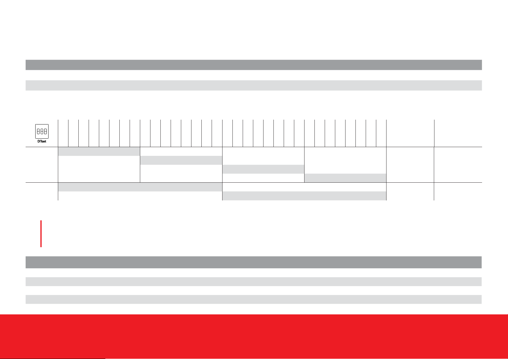
Schalter Standard 8 Standard 16 Switches Standard 8 Standard 16 Interrupteur Standard 8 Standard 16
1[AUS] +0 / [AN] +8 Keine Funktion 1 [OFF] +0 / [ON] +8 No function 1 [OFF] +0 / [ON] +8 Aucune fonction
2[AUS] +0 / [AN] +16 [AUS] +0 / [AN] +16 2 [OFF] +0 / [ON] +16 [OFF] +0 / [ON] +16 2 [OFF] +0 / [ON] +16 [OFF] +0 / [ON] +16
3[AUS] Zustand /
[AN] Reichweite
[AUS] Zustand /
[AN] Reichweite 3[OFF] State /
[ON] Range
[OFF] State /
[ON] Range 3[OFF] Etat /
[ON] Portée
[OFF] Etat /
[ON] Portée
ON
123
SRF 1
SRF 2
SRF 3
SRF 4
SRF 5
SRF 6
SRF 7
SRF 8
SRF 9
SRF 10
SRF 11
SRF 12
SRF 13
SRF 14
SRF 15
SRF 16
SRF 17
SRF 18
SRF 19
SRF 20
SRF 21
SRF 22
SRF 23
SRF 24
SRF 25
SRF 26
SRF 27
SRF 28
SRF 29
SRF 30
SRF 31
SRF 32
Schalter 1
Switch 1
Interrupteur 1
Schalter 2
Switch 2
Interrupteur 2
Standard 8
[AUS/OFF/OFF] [AUS/OFF/OFF]
[AN/ON/ON] [AUS/OFF/OFF]
[AUS/OFF/OFF] [AN/ON/ON]
[AN/ON/ON] [AN/ON/ON]
Standard 16 X* [AUS/OFF/OFF]
X* [AN/ON/ON]
Tabelle 1 / Table 1 / Table 1
* X -> keine Bedeutung/ don’t care / aucune importance
LED-Signale/
LED signals /
Signal LED /
4
LED Farbe / Colour / Couleur Bedeutung / Meaning / Sens
Power Grün / Green / Vert Gerät in Betrieb / Device in operation / Appareil en service
Fault Rot / Red / Rouge Fehler / Error / Erreur
Diagnostic Grün / Green / Vert Kommunikation vorhanden / Communication present / Communication existante
IO-Link Grün / Green / Vert IO-Link Daten werden übertragen / IO-Link data is transmitted / Des données IO-Link sont transmises
BERNSTEIN AG . Hans-Bernstein-Straße 1 . 32457 Porta Westfalica . www.bernstein.eu Seite 11 von 20
Betriebs- und Montageanleitung / Installation and Operating Instructions / Instructions de service et de montage
BERNSTEIN AG . Hans-Bernstein-Straße 1 . 32457 Porta Westfalica . www.bernstein.eu BERNSTEIN-Dok.: 0800000860 / Stand: 1 / 2018-04-17 / 0206-18 Seite 11 von 20
Anschluss /
Connection /
Raccordement
5
SRF DI-C-0/1-T
12 34
56 78
Power
Fault
Diagnostic
IO-Link
Bild 4
Fig. 4
SRF DI-C-8/1-T
Bild 5
Fig. 5
12 34
910 11 12
56 78
13 14 15 16
Power
Fault
Diagnostic
IO-Link
Anschlussplan Connecting diagram Diagramme de connexion
Klemme 01 + 24 V DC Terminal 01 + 24 V DC Borne 01 + 24 V DC
Klemme 02 IO-Link 24 V Terminal 02 IO-Link 24 V Borne 02 IO-Link 24 V
Klemme 03 IO-Link CQ Terminal 03 IO-Link CQ Borne 03 IO-Link CQ
Klemme 04 GND Terminal 04 GND Borne 04 GND
Klemme 05 Diagnose 1 IN Terminal 05 Diagnostic 1 IN Borne 05 Diagnostic 1 IN
Klemme 06 Diagnose 2 IN Terminal 06 Diagnostic 2 IN Borne 06 Diagnostic 2 IN
Klemme 07 Diagnose 1 OUT Terminal 07 Diagnostic 1 OUT Borne 07 Diagnostic 1 OUT
Klemme 08 Diagnose 2 OUT Terminal 08 Diagnostic 2 OUT Borne 08 Diagnostic 2 OUT
Klemme 09* Meldeausgang 01 Terminal 09* Signal output 01 Borne 09* Sortie de signal 01
Klemme 10* Meldeausgang 02 Terminal 10* Signal output 02 Borne 10* Sortie de signal 02
Klemme 11* Meldeausgang 03 Terminal 11* Signal output 03 Borne 11* Sortie de signal 03
Klemme 12* Meldeausgang 04 Terminal 12* Signal output 04 Borne 12* Sortie de signal 04
Klemme 13* Meldeausgang 05 Terminal 13* Signal output 05 Borne 13* Sortie de signal 05
Klemme 14* Meldeausgang 06 Terminal 14* Signal output 06 Borne 14* Sortie de signal 06
Klemme 15* Meldeausgang 07 Terminal 15* Signal output 07 Borne 15* Sortie de signal 07
Klemme 16* Meldeausgang 08 Terminal 16* Signal output 08 Borne 16* Sortie de signal 08
Klemme 17** Meldeausgang 09 Terminal 17** Signal output 08 Borne 17** Sortie de signal 09
Klemme 18** Meldeausgang 10 Terminal 18** Signal output 10 Borne 18** Sortie de signal 10
Klemme 19** Meldeausgang 11 Terminal 19** Signal output 11 Borne 19** Sortie de signal 11
Klemme 20** Meldeausgang 12 Terminal 20** Signal output 12 Borne 20** Sortie de signal 12
Klemme 21** Meldeausgang 13 Terminal 21** Signal output 13 Borne 21** Sortie de signal 13
Klemme 22** Meldeausgang 14 Terminal 22** Signal output 14 Borne 22** Sortie de signal 14
Klemme 23** Meldeausgang 15 Terminal 23** Signal output 15 Borne 23** Sortie de signal 15
Klemme 24** Meldeausgang 16 Terminal 24** Signal output 16 Borne 24** Sortie de signal 16
SRF DI-C-16/1-T
Bild 6
Fig. 6
12 34
910 11 12
56 78
13 14 15 16
Power
Fault
Diagnostic
IO-Link
17 18 19 20
21 22 23 24
* Diese Klemmen sind in der Geräteversion
Standard 08 und 16 vorhanden! (Bild 5 und 6)
** Diese Klemmen sind nur in der
Geräteversion Standard 16 vorhanden! (Bild 6)
* These terminals are provided when
using version Standard 08 and 16! (Fig. 5 and 6)
* *These terminals are only provided when
using version Standard 16! (Fig. 6)
* Ces bornes sont disponibles dans la version
appareil Standard 08 et 16 disponibles! (Fig. 5 et 6)
** Ces bornes sont seulement disponibles
en utilisant la version standard 16! (Fig. 6)

BERNSTEIN AG . Hans-Bernstein-Straße 1. 32457 Porta Westfalica . www.bernstein.eu Seite 12 von 20
Betriebs- und Montageanleitung / Installation and Operating Instructions / Instructions de service et de montage
BERNSTEIN AG . Hans-Bernstein-Straße 1. 32457 Porta Westfalica . www.bernstein.eu BERNSTEIN-Dok.: 0800000860 / Stand: 1 / 2018-04-17 / 0206-18 Seite 12 von 20
Anschlussplan Connecting diagram Diagramme de connexion
Klemme 01 + 24 V DC Terminal 01 + 24 V DC Borne 01 + 24 V DC
Klemme 02 IO-Link 24 V Terminal 02 IO-Link 24 V Borne 02 IO-Link 24 V
Klemme 03 IO-Link CQ Terminal 03 IO-Link CQ Borne 03 IO-Link CQ
Klemme 04 GND Terminal 04 GND Borne 04 GND
Klemme 05 Diagnose 1.1 IN Terminal 05 Diagnostic 1.1 IN Borne 05 Diagnostic 1.1 IN
Klemme 06 Diagnose 1.2 IN Terminal 06 Diagnostic 1.2 IN Borne 06 Diagnostic 1.2 IN
Klemme 07 Diagnose 2.1 IN Terminal 07 Diagnostic 2.1 IN Borne 07 Diagnostic 2.1 IN
Klemme 08 Diagnose 2.2 IN Terminal 08 Diagnostic 2.2 IN Borne 08 Diagnostic 2.2 IN
Klemme 09 Diagnose 3.1 IN Terminal 09 Diagnostic 3.1 IN Borne 09 Diagnostic 3.1 IN
Klemme 10 Diagnose 3.2 IN Terminal 10 Diagnostic 3.2 IN Borne 10 Diagnostic 3.2 IN
Klemme 11 Diagnose 4.1 IN Terminal 11 Diagnostic 4.1 IN Borne 11 Diagnostic 4.1 IN
Klemme 12 Diagnose 4.2 IN Terminal 12 Diagnostic 4.2 IN Borne 12 Diagnostic 4.2 IN
Klemme 13 Diagnose 5.1 IN Terminal 13 Diagnostic 5.1 IN Borne 13 Diagnostic 5.1 IN
Klemme 14 Diagnose 5.2 IN Terminal 14 Diagnostic 5.2 IN Borne 14 Diagnostic 5.2 IN
Klemme 15 Diagnose 6.1 IN Terminal 15 Diagnostic 6.1 IN Borne 15 Diagnostic 6.1 IN
Klemme 16 Diagnose 6.2 IN Terminal 16 Diagnostic 6.2 IN Borne 16 Diagnostic 6.2 IN
SRF DI6-C-0/1-T
Bild 7
Fig. 7
12 34
910 11 12
56 78
13 14 15 16
Power
Fault
Diagnostic
IO-Link

BERNSTEIN AG . Hans-Bernstein-Straße 1 . 32457 Porta Westfalica . www.bernstein.eu Seite 13 von 20
Betriebs- und Montageanleitung / Installation and Operating Instructions / Instructions de service et de montage
BERNSTEIN AG . Hans-Bernstein-Straße 1 . 32457 Porta Westfalica . www.bernstein.eu BERNSTEIN-Dok.: 0800000860 / Stand: 1 / 2018-04-17 / 0206-18 Seite 13 von 20
Abmessungen/
Dimensions/
Dimensions
6
Montage/
Installation/
Montage
7
12 34
910 11 12
56 78
13 14 15 16
Power
Fault
Diagnostic
IO-Link
21 22 23 24
17 18 19 20
Bild 8
Fig. 8
Für die Montage gelten die üblichen Methoden bei
Hutschienen-Modulen (TS35).
For assembly, the standard methods for T-rail modules apply
(TS35).
Pour le montage, les méthodes habituelles pour les modules à
profilé-chapeau (TS35) s’appliquent.

BERNSTEIN AG . Hans-Bernstein-Straße 1. 32457 Porta Westfalica . www.bernstein.eu Seite 14 von 20
Betriebs- und Montageanleitung / Installation and Operating Instructions / Instructions de service et de montage
BERNSTEIN AG . Hans-Bernstein-Straße 1. 32457 Porta Westfalica . www.bernstein.eu BERNSTEIN-Dok.: 0800000860 / Stand: 1 / 2018-04-17 / 0206-18 Seite 14 von 20
Technische Daten /
Technical Data /
Caractéristiques techniques
8
Elektrische Daten / Electrical Data / Caractéristiques électriques
Bemessungsbetriebsspannung / Rated supply voltage / Plage de tension de fonctionnement Ue24 V, verpolungssicher /Reverse polarity protection /Protégé contre l’inversion des pôles, +25 %, - 20 %
Spannungspegel / Voltage level / Niveau de tension gemäß/ according to / selon Typ 3 EN 61131-2
Bemessungsbetriebsstrom / Rated operating current / Courant de service assigné Ie50 mA (pro Meldeausgang/ each signal output / chaque sortie de signal)
Spannungsfall / Voltage drop / Chute de tension Ud< 3,5 V (pro Meldeausgang/ each signal output / chaque sortie de signal)
Leerlaufstrom / No-load current / Courant à vide I0≤ 15 mA
Meldeausgänge / Signal outputs / Sorties de signal
PNP, Schließer (geschlossen bei geöneter Schutzeinrichtung) /
PNP, N.O. (closed by opened protective device) /
PNP, contact à fermeture (fermé lorsque le dispositif de protection est ouvert)
Schnittstellen / Interfaces / Interfaces USB 2.0
NFC
Kurzschlussschutz / Short–circuit protection/ Protection contre les courts-circuits ja / yes / oui
EMV / EMC / Compatibilité Électromagnétique gemäß EN 61326-1 und EN 61131-9 / according to EN 61326-1 and EN 61131-9 /
selon EN 61326-1 et EN 61131-9
Mechanische Daten / Mechanical Data / Caractéristiques techniques
Gehäuse / Enclosure / Boîtier PA-GF, schwarz / black / noir
Frontplatte PBT, lichtgrau / light grey / gris clair
Anzeigen / Indication / Indicateurs 4 x LED
Umgebungstemperatur / Ambient temperature / Température ambiante 0 °C - +60 °C
Lagertemperatur / Storage temperature / température de stockage 0 °C - +60 °C
Aufstellungshöhe / Altitude / Altitude ≤ 2000 m NHN
Anschlussart / Connection / Type de raccordement Schraubklemmen / screw terminals / borne à vis
Schutzart / Protection type / Degré de protection IP20
Schutzklasse nach / Protection class according to / Classe de protection selon EN IEC 61558 III
IO – LINK Spezikation / IO – LINK specication / IO – LINK spécication
IO – LINK Spec V 1.1 Konform / compliant / conforme
Geschwindigkeit / Speed / La vitesse COM 2 38400 baud
BERNSTEIN AG . Hans-Bernstein-Straße 1 . 32457 Porta Westfalica . www.bernstein.eu Seite 15 von 20
Betriebs- und Montageanleitung / Installation and Operating Instructions / Instructions de service et de montage
BERNSTEIN AG . Hans-Bernstein-Straße 1 . 32457 Porta Westfalica . www.bernstein.eu BERNSTEIN-Dok.: 0800000860 / Stand: 1 / 2018-04-17 / 0206-18 Seite 15 von 20
Typenschlüssel/
Type code /
Code des types
9
Technologie /
Technology /
Technologie
(1)
-
Produkttyp /
Product type /
Type de produit
(2)
-
Bauform /
Design /
Forme de construction
(3)
-
Anzahl PNP Ausgänge /
Number of PNP outputs /
Nombre de sorties PNP
(4)
-
Schnittstellen /
Interfaces /
Interfaces
(5)
-
Anschluss /
Connection /
Raccordement
(6)
1. Technologie / Technology / Technologie
Bei der Technologie handelt es sich um eine xe Benennung.
Für die RFID Diagnosemodule lautet die Abkürzung:
SRF (Safety RFID)
The technology is a xed designation. For the RFID diagnostic
modules, the abbreviation is: SRF (Safety RFID)
La technologie est une désignation xe. Pour les modules de
diagnostic RFID, l‘abréviation est la suivante: SRF (Safety RFID)
2. Produkttyp / Product type / Type de produit
Kürzel / Abbreviation / Abréviation Bedeutung / Meaning / Signication
DI Diagnosemodul für eine Diagnosekette / Diagnostics module for a diagnostics chain /
Module de diagnostic pour une chaîne de diagnostic
DI6 Diagnosemodul für 6 Diagnosekette / Diagnostics module for 6 diagnostics chains /
Module de diagnostic pour 6 chaînes de diagnostic
3. Bauform / Design / Forme de construction
Kürzel / Abbreviation / Abréviation Bedeutung / Meaning / Signication
CHutschienengehäuse zur Schaltschrankmontage / T-rail housing for switch cabinet mounting /
Boîtier à prolé-chapeau pour un montage dans une armoire électrique
FEckiges Gehäuse (30x68x15) zu Feldmontage / Angular housing (30x68x15) for eld mounting /
Boîtier carré (30x68x15) pour un montage sur le terrain
4. Anzahl PNP Ausgänge / Number of PNP outputs / Nombre de sorties PNP
Kürzel / Abbreviation / Abréviation Bedeutung / Meaning / Signication
00 x PNP Out
88 x PNP Out
16 16 x PNP Out

BERNSTEIN AG . Hans-Bernstein-Straße 1. 32457 Porta Westfalica . www.bernstein.eu Seite 16 von 20
Betriebs- und Montageanleitung / Installation and Operating Instructions / Instructions de service et de montage
BERNSTEIN AG . Hans-Bernstein-Straße 1. 32457 Porta Westfalica . www.bernstein.eu BERNSTEIN-Dok.: 0800000860 / Stand: 1 / 2018-04-17 / 0206-18 Seite 16 von 20
5. Schnittstellen / Interfaces / Interfaces
Kürzel / Abbreviation / Abréviation Bedeutung / Meaning / Sens
0Keine weiteren Schnittstellen / No other interfaces / Pas d‘autres interfaces
1IO-Link + NFC + USB
2IO-Link + NFC
6. Anschluss / Connection / Raccordement
Kürzel / Abbreviation / Abréviation Bedeutung / Meaning / Sens
A# Kabel mit oenem Ende (# = Länge in Meter)/ Cable with open end (# = Length in meters) /
Câble ouvert à l‘extrémité (# = Longueur en mètres)
BM8 Stecker / M8 plug / Connecteur M8
CM12 Stecker / M12 plug / Connecteur M12
D# Kabel mit M8 Stecker (# = Länge in Meter) / cable with M8 plug (# = Length in meters) /
connecteur M8 avec câble (# = Longueur en mètres)
E# Kabel mit M12 Stecker (# = Länge in Meter) / cable with M12 plug (# = Length in meters) /
connecteur M12 avec câble (# = Longueur en mètres)
TAnschlussklemmen / Connection terminals / Borne de raccordement
XAnschluss siehe Datenblatt / Connection see data sheet / Connexion voir la che technique
6. Sonderheiten (optional) / Special characteristics (optional) /Caractéristique spéciale (en option)
Beispiel für Diagnosemodul zur Schrankmontage / Example for Diagnostics module for cabinet mounting / Exemple de Module de diagnostic pour un montage dans une armoire électrique:
SRF DI-C-16/1-T
Beispiel für Diagnosemodul zur Feldmontage mit 2,2 m Kabel und oenem Ende / Example for Diagnostics module for eld mounting with 2,2 m open cable end /
Exemple de Module de diagnostic pour un montage sur le terrain avec extrémité de câble ouverte de 2,2 m:
SRF DI-F-0/1-A2,2
Beispiel für Diagnosemodul zur Feldmontage mit 2 m Kabel und M12 Stecker / Example for Diagnostics module for eld mounting with 2 m cable and M12 plug /
Exemple de Module de diagnostic pour un montage sur le terrain avec câble de 2 m et connecteur M12:
SRF DI-F-0/1-E2

BERNSTEIN AG . Hans-Bernstein-Straße 1 . 32457 Porta Westfalica . www.bernstein.eu Seite 17 von 20
Betriebs- und Montageanleitung / Installation and Operating Instructions / Instructions de service et de montage
BERNSTEIN AG . Hans-Bernstein-Straße 1 . 32457 Porta Westfalica . www.bernstein.eu BERNSTEIN-Dok.: 0800000860 / Stand: 1 / 2018-04-17 / 0206-18 Seite 17 von 20
Instandhaltung / Wartung/
Maintenance / Service/
Entretien / Maintenance
10
Das Produkt bedarf keiner gesonderten Instandhaltungs- oder
Wartungsprozeduren.
The product requires no special servicing or maintenance
procedures.
Le produit ne requiert aucune procédure d’entretien ou de
maintenance particulière.
DIN EN 61131-2
DIN EN 61131-9
DIN EN 61326-1
Vorschriften abhängig von der Ausführung
Standards depending on the version
Diréctives selon la version
EU-Konformität
EU-Conformity
Conformité CE
Richtlinie
Directive
Diréctive
2011/65/EU (RoHS II)
2014/30/EU (EMV / EMC / Directive Compatibilité Électromagnétique)
2012/19/EU (EU-WEEE II)
ect e
cCSAus (class 2 Power source)
Zulassungen (in Vorbereitung) /
Approvals (in preparation) /
Homologations (en préparation)
Vorschriften / Zulassungen / Richtlinien
Standards / Approvals / Directive
Diréctives / Homologations / Diréctive
11

BERNSTEIN AG . Hans-Bernstein-Straße 1. 32457 Porta Westfalica . www.bernstein.eu Seite 18 von 20
Betriebs- und Montageanleitung / Installation and Operating Instructions / Instructions de service et de montage
BERNSTEIN AG . Hans-Bernstein-Straße 1. 32457 Porta Westfalica . www.bernstein.eu BERNSTEIN-Dok.: 0800000860 / Stand: 1 / 2018-04-17 / 0206-18 Seite 18 von 20
Technische Daten
Produktspezifische Eigenschaften sowie weitere technische
Daten entnehmen Sie bitte dem Technischen Datenblatt.
Weiterführende Informationen erhalten Sie unter
www.bernstein.eu.
Haftungsausschluss
Bei Verletzung der Anweisungen erlischt die Herstellerhaftung.
Liability disclaimer
By breach of the given instructions manufacturer’s liability
expires.
Exclusion de la responsabilité
La responsabilité du fabricant est annulée si les instructions ne
sont pas respectées.
Technical data
Please refer to the technical data sheet for product-specific
characteristics and other technical data.
For further information please visit www.bernstein.eu.
Caractéristiques techniques
Pour les caractéristiques du produit et les données techniques,
veuillez vous référer à la fiche technique.
Rendez-vous sur www.bernstein.eu pour des informations
complémentaires.
Die deutsche Sprachfassung ist die Originalbetriebs- und
Montageanleitung. Bei anderen Sprachen handelt es sich um
die Übersetzung der Originalbetriebs- und Montageanleitung.
The original operating and installation instructions are the
German language version. Other languages are a translation of
the original operating and installation instructions.
La version allemande est la langue d’origine des instructions
de service et de montage. Les autres langues ne sont qu’une
traduction des instructions de service et de montage en langue
allemande.
Haftungsausschluss – Technische Daten – Konformitätserklärungen/
Liability disclaimer – Technical Data – Declarations of conformity
Exclusion de la responsabilitè – Caractéristiques techniques –
Déclaration de conformité
12
BERNSTEIN AG . Hans-Bernstein-Straße 1 . 32457 Porta Westfalica . www.bernstein.eu Seite 19 von 20
Betriebs- und Montageanleitung / Installation and Operating Instructions / Instructions de service et de montage
BERNSTEIN AG . Hans-Bernstein-Straße 1 . 32457 Porta Westfalica . www.bernstein.eu BERNSTEIN-Dok.: 0800000860 / Stand: 1 / 2018-04-17 / 0206-18 Seite 19 von 20

BERNSTEIN AG . Hans-Bernstein-Straße 1. 32457 Porta Westfalica . www.bernstein.eu Seite 20 von 20
Betriebs- und Montageanleitung / Installation and Operating Instructions / Instructions de service et de montage
BERNSTEIN AG . Hans-Bernstein-Straße 1. 32457 Porta Westfalica . www.bernstein.eu BERNSTEIN-Dok.: 0800000860 / Stand: 1 / 2018-04-17 / 0206-18 Seite 20 von 20
Notizen/
Notes/
Notes
This manual suits for next models
4
Table of contents
Other BERNSTEIN Diagnostic Equipment manuals


