Siemens Intelli-Arc User manual

1
Intelli-ArcTM Diagnostic Tool
Instruction Sheet
Base unit
Handheld device

2
DANGER
Hazardous voltage. Will cause death or serious injury.
This device necessitates working on or near equipment with exposed electrical
hazards. Turn off and lock out power supplying equipment before connecting Intelli-Arc
Diagnostic Tool. Ensure a safe work zone before re-energizing equipment for testing
purposes.
SAFETY INSTRUCTIONS
1. Intelli-Arc Diagnostic Tool must be installed and operated only by a
qualified electrician.
2. To be installed only on a single phase 120VAC grounded system.
3. The Intelli-Arc Diagnostic Tool is not a protective device. For use only on
the load side of a listed branch circuit protection device rated at 20
Amperes or less.
4. To prevent severe shock or electrocution, always turn the power off
before working on or inside equipment.
5. It is the qualified electrician’s responsibility to ensure a secured, safe
working area around the enclosure before turning on power to the
equipment.
6. Intelli-Arc Diagnostic Tool is intended for temporary installation only.
Never leave the work site with the Diagnostic Tool connected.
7. Always replace all doors and covers before departing from the work site.
CAUTION
Hazard of Equipment Damage.
Will cause Damage to the Intelli-Arc Diagnostic Tool.
Do not reverse-feed or back-wire. Do not subject to megger, high voltage,
or hi-pot test. Remove the Intelli-Arc Diagnostic Tool before high-potting
occurs on the system or on the circuit.

3
General
The Intelli Arc Diagnostic Tool is intended to analyze house hold circuits to localize arc faults. It can indicate early
warnings of possible arcing before an AFCI breaker would trip. The Intelli Arc Diagnostic Tool may show contributions
from different loads that each individually would not create a trip condition. However, the combination of these loads may
create a situation that results in a trip condition of an AFCI breaker.
The Intelli Arc Detector does NOT protect from arcing in any circuit and it does not prevent any damage that an arc fault
can cause. It is a measurement tool to support the detection of an arc fault.
The Intelli Arc Diagnostic Tool is for indoor use only for measurements of category III in branch circuits of maximum 20A
rated current.
If this product is used in a manner not specified by the manufacturer, the protection provided by the equipment may be
impaired.
Any changes or modifications not expressly approved by the grantee of this device could void the user's authority to
operate the equipment
Radio Frequency Interference Warnings & Instructions
This equipment has been tested and found to comply with the limits for a Class B digital device, pursuant to part 15 of the
FCC Rules. These limits are designed to provide reasonable protection against harmful interference in a residential
installation. This equipment generates, uses and can radiate radio frequency energy and, if not installed and used in
accordance with the instructions, may cause harmful interference to radio communications. However, there is no
guarantee that interference will not occur in a particular installation. If this equipment does cause harmful interference to
radio or television reception, which can be determined by turning the equipment off and on, the user is encouraged to try
to correct the interference by one or more of the following measures:
-Reorient or relocate the receiving antenna.
-Increase the separation between the equipment and receiver.
-Connect the equipment into an outlet on a circuit different from that to which the receiver is connected.
-Consult the dealer or an experienced radio/TV technician for help.
One Intelli Arc Diagnostic Tool set consists of one Carrying Case Including:
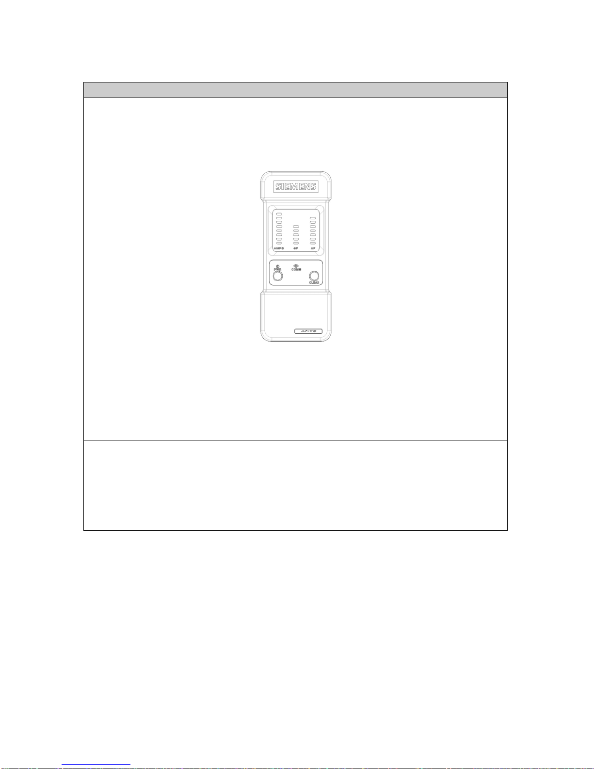
1. 1 Intelli Arc Diagnostic Tool IDT5000B – Base Unit
2. 1 Intelli Arc Diagnostic Tool IDT5000H – Handheld Unit
3. 4 wires AWG 12, 4-5 ft. length
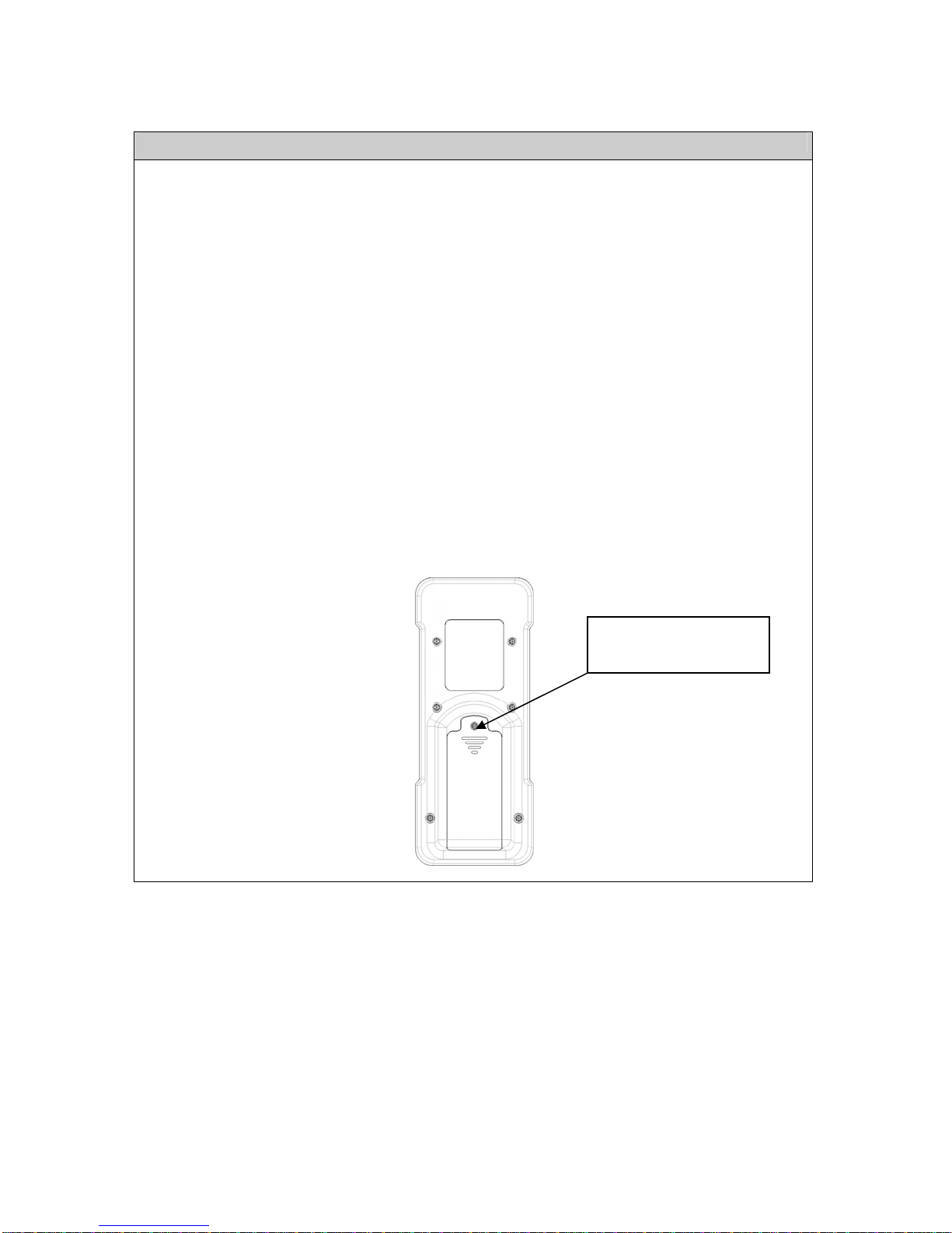
4. 2 AA alkaline batteries for the Handheld Unit
5. 8 replacement screws for the terminal lugs of the Base Unit
6. 1 Instruction Sheet
For technical support related to the operation of this device please contact:
Siemens Energy & Automation, Inc.
3333 Old Milton Parkway
Alpharetta, GA 30005
1-800-964-4114

4
INSTALLATION INSTRUCTIONS
See Figures 1 & 2
1. Turn “OFF” and lock out the power to the equipment in which the Intelli-Arc Diagnostic Tool is to be installed.
2. Move the handle of the breaker on the circuit to be analyzed to the “OFF” position. This circuit breaker serves as the
disconnect device tor the Intelli-Arc Diagnostic Tool.
3. Remove the load side hot and neutral wires from the breaker of the branch circuit to be tested. Panelboard neutral
(pigtail) wire must remain connected to panel neutral bar.
4. Connect the two wires removed in step 3 to the load terminals of the base unit. Connect 12 AWG copper
conductors from the load terminals of the AFCI breaker to be tested to the line terminals of the Intelli-Arc Diagnostic
Tool base unit.
a) Base unit of Diagnostic Tool draws power from the power line. No batteries are used in this device.
b) Each connection between Intelli-Arc Diagnostic Tool and the circuit breaker must have a length between 4 and
5 feet.
c) Strip insulation of wires should be limited to a length of 3/8 inch. See Intelli-Arc Diagnostic Tool base unit label
for stripping guide.
d) Ensure that wire connectors are properly torqued. Do not over-torque. See Intelli-Arc Diagnostic Tool base unit
label and circuit breaker label for the respective torque criteria.
e) Wiring scheme to install base unit of Diagnostic Tool:
Load Hot
min 4 ft.
Load Neutral
min 4 ft.
Branch
Circuit
Line Hot
Pigtail
Neutral Bar
Load Hot
min 4 ft.
Panel Neutral
min 4 ft.
Branch
Circuit
Line Hot
Neutral Bar
Figure 1 - AFCI or GFCI Breaker Figure 2 - Conventional Breaker
5. For strain relief a lanyard opening is provided to mount the Base Unit in a safe and convenient location.
6. Establish a secured, safe work area around the load center or panelboard.
7. While exercising caution, turn power back on to the load center or panelboard.
8. Follow operating instructions.
9. Turn off and lock out power supplying the device before removing base unit. Restore all branch circuit connections
and close cover if testing is complete. Return to step 1 of Installation Instructions to test another branch circuit.

5
OPERATING INSTRUCTIONS
1. De-energize all individual loads on the branch circuit under evaluation at the outlet (switch, receptacle, junction box,
work box, etc.).
2. While exercising caution, turn on the branch circuit breaker
3. Turn “ON” the breaker supplying power to the branch circuit under evaluation.
4. Turn “ON” the handheld device (Fig. 3). Note: To confirm functionality of all LEDs, see LED Test Procedure below.
Figure 3
5. The communication LED will start blinking after the handheld establishes communication with the base unit. The
LED will continue blinking as long as the handheld maintains communication.
6. Energize, and then de-energize loads one by one on the branch circuit being evaluated, observing LED indications
on handheld device after each load is energized and de-energized. (See “LED Indications” for more details.)
7. The “GF” and “AF” LEDs will lock in the top (red) position when any event causes the device to read maximum
levels, even if the event ceases to exist. Press the “CLEAR” button to continue evaluation of the branch circuit.
8. Turn off and lock out power supplying the device before removing base unit. Restore all branch circuit connections.
Close cover if testing is complete or return to step 1 of Installation Instructions to test another branch circuit.
9. Always remove Intelli-Arc Diagnostic Tool and replace load center or panelboard cover before leaving the work site.
LED Test Procedure
1. Turn “OFF” handheld device.
2. Press and hold “CLEAR” button on handheld.
3. Press “PWR” button on handheld device, while continuing to hold “CLEAR” button.
4. The LED columns will light up one by one and each top LED will remain on so long as the “CLEAR” button is
pressed.
5. If any LED fails to illuminate during the procedure then the handheld device must be replaced.
6. Once the “CLEAR” button is released the top LEDs will clear and the handheld is ready for operation.

6
LED Indications
Three sets of LED indicators are provided on the handheld device for use in troubleshooting branch circuit issues. These
three indications give information regarding current (“AMPS”), ground fault level (“GF”), and arc fault level (“AF”).
Current (“AMPS”)
1. The full scale current for this LED indication is 20+A.
2. LED indicators do not increase by uniform intervals.
3. The 5 A point is marked on handheld device for reference.
Ground Fault (“GF”)
1. The full scale current for this LED indication is 50+ mA.
Arc Fault (“AF”)
1. This LED indication does not display in reference to current level but rather in severity of events, with a full scale
reading (red LED) representing an event that is very likely to cause an AFCI device to trip.
2. Partial readings (yellow LEDs) may or may not be suspect issues to evaluate.
3. Transitional events, i.e. turning on an appliance, are likely to register as some low level on the Arc Fault scale.

7
Technical Specification
Operating ambient temperature: 5ºC – 40ºC (41ºF – 104 ºF)
Maximum relative humidity: 80% for temperatures up to 31ºC (88ºF)
decreasing linearly to 50% at 40ºC (104ºF)
Environment: Indoor use at altitude up to 2000 m (6561 feet)
Range of operating voltage: 108V – 132V
Pollution degree: Pollution degree 2
Wire requirements: 4 Wires
4 – 5 feet length
60 / 75ºC
CU#14-8 / AL#10-8
Maximum torque for terminal lugs: 25 lb-in
Handheld Batteries: The Diagnostic Tool handheld device operates on
2 AA batteries. These batteries may be accessed
from the back side of the handheld device. See
Figure 4 below. For battery disposal, please follow
instructions of battery manufacturer.
Battery types: Alkaline
Figure 4
Battery Access
1) Remove screw
2) Lift plastic cover
Table of contents
Other Siemens Diagnostic Equipment manuals