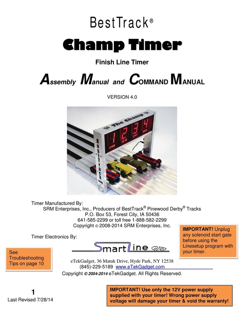
BestTrack Champ Timer SS User manual

BestTrack®
Champ Timer SS
Timer Instruction Manual
SRM Enterprises, Inc., Producers of BestTrack®Pinewood Derby®Tracks
P.O. Box 53, Forest City, IA 50436
Phone: 641-585-2299
Copyright © 2022 SRM Enterprises, Inc.
IMPORTANT! Use only the 12V power supply
supplied with your timer! Wrong power
supply voltage will damage your timer &
void the warranty!

2
Champ Timer SS
•Displays 1 to 8 lanes.
•Large (2 ¼ inch) displays can be read at a distance.
•6.5 inch clearance above track.
•Use with or without a computer connection.
•Computer connection included.
•Reset button and timed automatic reset.
•Easy to install on your BestTrack®Pinewood Derby®Track.
Champ Timer system consists of:
•Champ Timer unit with 1-8 displays.
•AC Power Adapter.
•50 ft. RS-232 Serial Cable for computer connection.
•Reset Switch & Start Gate Switch with mounting brackets.
•50 ft. Reset Switch/Start Gate Switch Cable.
Warranty
The Champ Timer has a 3-year warranty on the electronics and against
manufacturing defects.
This warranty does not cover damages such as incidental or physical
damage, damage due to misuse, modifications, or incompatible
equipment/accessories being used.
We need to be notified of damaged/missing parts within 30 days of the delivery of your order.

3
Mounting and Operating Instructions
Mounting Champ Timer Hardware
Follow these steps to install the Champ Timer over the track.
Your Champ
Timer comes
completely
assembled, ready
to be mounted on
your BestTrack®
Pinewood Derby®
track. (4-lane
timer shown)
Slide two ¼-20 X 1” long hex head bolts (included) in the
track outer mounting slots of the timer section of track.
(You will have to remove the connector angle at one end
of the timer section if your track is already assembled.)
Use a carpenter’s square to align these bolts with the
center timer sensor holes punched in your track. (4-lane
track shown). Tighten a nut on this bolt to hold it in
place.
IMPORTANT! Tighten a nut on this bolt to hold it in
place. This will center the timer above the sensor
holes in the track.

4
Slide the timer over the end of the track with the
sensor bar beneath the track. Place the timer over
the bolts installed in the previous step using the
timer’s track mounting holes (holes shown in picture
on previous page). Then place a washer over each
bolt and secure the timer with an additional nut on
each bolt.Finger tighten only. Do not over
tighten.
Do Not Over Tighten the
Mounting Bolts!
Finger tighten only.

5
Reset Switch & Jack Bracket Mounting
Slide a ¼-20 X ½” long hex head bolt into the mounting slot at the edge of the
track near the start lever assembly and mount the reset switch bracket as
shown in the picture below. Use a hex nut to fasten the bracket to the track.
Start Gate Switch Bracket Mounting
Slide a ¼-20 X ½” long hex head bolt into the third mounting slot from the
edge of the track. Slide the start gate switch lever(shown below in blue for
picture clarity) under the start gate assembly as shown, so that the switch is
activated as the start gate drops. Use a hex nut to fasten the bracket to the
track.
Adjust the bracket position and/or start gate switch lever (shown in blue) so
that the start gate switch lever is fully depressed. You should hear the
start switch “click” when the start gate is put into the up “ready to race”
position. If not, you may need to slightly bend the start gate switch lever
on the switch down towards the floor.

6
1. Plug the power supply into the power supply jack on the Champ Timer unit.
IMPORTANT! Use only the 12V DC power supply supplied with your timer!
Wrong power supply voltage will damage your timer & void the warranty!
2. Plug the 9-Pin RS-232 Serial Cable into the Champ Timer computer connection port,
shown in picture above. Plug the other end of this cable into the RS-232 Serial to
USB Adapter. Plug the Serial to USB Adapter into a USB port on your computer. Use
the CD that comes with the USB to Serial Adapter to install the driver. Note: The
adapter driver might download and install automatically if you are already connected
to the internet when you plug the adapter into the USB port on your computer.
3. Plug one end of the Reset/Start Switch Cable into the Champ Timer start switch jack,
shown in the picture above. Plug the other end into the jack on the Reset Switch &
Jack Bracket, shown on page 5. Carefully make sure that the cable is fully inserted
into both jacks.
Note: WIRING INFORMATION - The supplied start gate switch has three connections
marked C(Common), NC (Normally Closed) and NO (Normally Open). The preferred
method is to have the start gate switch lever depressed before the race and un-
pressed when the race starts. This method requires the use of the C and NC
connections as shown in the picture below. (Top & bottom connections.)
Use the top & bottom connections, leaving
the middle one open.

7
4. Using the Champ Timer AC adapter, power up the Champ Timer.
IMPORTANT! Use only the 12V DC power supply supplied with your timer!
5. Timer Sequence:
When the timer is first plugged in at startup, you will see all lane displays showing an
8, then a lane number illuminates in each lane. (See #6 & #7 below). The display will
then blank out.
If the start gate is in the up (ready to race) position you will see a lower case “u” in
each lane indicating the start gate is “up”.
When the start gate drops, the “u” will change to a lower case “r” indicating the
“race”has started and the elapsed time has started counting.
As each car crosses the finish line the “r” will change to the place of finish and the
display will also show the elapsed time for that lane.
6. Default Mode (doing nothing during power up, with no computer connection) - The
results remain on the displays for 15 seconds, unless the Reset Button is pressed.
All lanes are active in default mode. At startup all displays will show their respective
lane numbers (lane 1 '1', lane 2 '2', etc.)
If using GPRM (Grand Prix Race Manager) software with a computer connection, skip
to #9 below.
7. No Timeout Mode (Timer will not reset until the reset button is pushed) -
Activated by pressing and holding in the Reset Button before and during power up
until the number 2 is displayed in each lane. The timer displays will show all '2's
instead of the lane's respective number (lane 1 '1', lane 2 '2', etc.). This mode allows
the results of a race to be displayed indefinitely until the Reset Button is pressed. All
lanes are active in No Timeout Mode.
8. Lane Mask Option (Turning Off Lanes) –
Lane masking can be done in either Default Mode or No Timeout Mode.
(See #6 & #7 above).
Choose which one of these modes prior to using the lane masking option.
Before powering up the timer, place something over the sensors of the lanes that you
want to be masked/turned off. Power up the timer.
Masking when using Default Mode:When n's are displayed on the blocked lanes,
press the Reset Button for approximately 5 seconds to have those lanes turn off.
Masking when using No Timeout Mode:Release the reset button after the 2’s are
displayed in the lanes. When n’s are then displayed on the blocked lanes, press the
reset button again for approximately 5 seconds to turn those lanes off.
Note: This is a one-time masking for both modes - if lanes need to be reconfigured,
unplug, and then restart the timer. If the timer is unplugged, the lanes will need to be
masked again.

8
9. Computer Connection Mode - This mode becomes active once a back-and-forth
communication has been established between GPRM (Grand Prix Race Manager)
software and the timer. To connect to GPRM software, go to the software Hardware
Settings page and make sure “The Champ” radio button is selected. Click on the
software “Start Testing” button to connect the timer to the software. Run a test race on
the Hardware Settings page.
Note: Once communication with GPRM has been established, all lanes will be turned
back on if previously masked (see #8 above). You will now use the GPRM software to
mask (turn off) the lanes. The timer will also be in No Timeout Mode (see #7 above)
and will not reset on its own. You can reset the timer from within the software or by
using the reset button.
10. When using a Serial to USB Adapter -
If you are using a Serial to USB Adapter to connect your Champ Timer to a laptop or
other computer, be sure to install the drivers for your USB Adapter. Your timer will not
communicate with the computer if you do not have the drivers installed for the Serial to
USB Adapter. If a driver disc was not included with your Serial to USB Adapter, you
can download a new version from the manufacturer’s web site.
Note: The adapter driver might download and install automatically if you are already
connected to the internet when you plug the adapter into a USB port on your
computer.
TROUBLESHOOTING:
If you have a “n” in one or more lanes, this means that the lower sensor cannot see
the infrared LED light shining down on the track from the upper part of the timer.
Check to see if the lower sensors on the sensor bar are aligned with the sensor holes
in the track. Check to make sure that no debris is blocking the sensor. Look
at the infrared LED light that shines down on to the track and make sure it is pointing
straight down and did not get tipped to one side. The LED can be gently repositioned if
needed. The infrared light from the upper LEDs is invisible.
If the first car is showing a “0.0000” elapsed time on a race, the timer is not
receiving the start signal from the start gate switch. Check to make sure the start gate
switch/reset cable is plugged in all the way. Also, check to make sure the start gate
switch lever is fully depressed and that you can hear the start gate switch “click” when
the start gate is put up into the “ready to race” position. You may need to slightly bend
the metal lever of the start gate switch down towards the floor so that it contacts the
start gate sooner.
If you are getting 9.9999 for all the times for your cars, you may have the start
gate switch hooked up incorrectly. See the diagram shown on page 6.
The middle connection of the start gate switch should not be connected, see the
diagram shown on page 6.
Table of contents
Other BestTrack Timer manuals
