manuals.online logo
Brands
  1. Home
  2. •
  3. Brands
  4. •
  5. Zamel
  6. •
  7. Timer
  8. •
  9. Zamel ASM-04 User manual

Zamel ASM-04 User manual

STAIRCASE LIGHTING TIMER ASM-04 USER’S MANUAL
ZAMEL Sp. z o.o.
ul. Zielona 27, 43-200 Pszczyna, Poland
Tel. +48 32 210 46 65, Fax +48 32 210 80 04
www.zamel.com, e-mail: [email protected]
plik: asm-04_inst_ext_gb | modykacja:17.07.2019
APPEARANCE
FEATURES
TECHNICAL DATA
DESCRIPTION
ASM-04
Power input terminals: L; N
Rated supply voltage: 230 V AC
Supply voltage tolerance: -15 to +10%
Rated mains frequency: 50 / 60 Hz
Rated current load: 26 mA
Release terminals: IN; IN; IN
Release control current: 0.5 mA
Time delay setting range: 10 s to 10 min (with a rotary potentiometer)
Time delay setting resolution: ±10%
Time delay setting repeatability: ±5%
Power threshold setting: 0.1 to 2 kW
Power threshold trip off delay: 40 s
Power overload indication: red LED
Transmitter contact ratings: 1NO – 16 A / 250 V AC1 4,000 VA
Wiring terminals: 7
Wiring size: 0,2 ÷ 2,50 mm2
Operating temperature: -20 ÷ +45oC
Installation orientation: any
Installation type: DIN rail
Protection grade: IP20
Overvoltage category: II
Pollution class: 2
Dimensions: single module 90 x 17,5 x 66 mm
Weight: 0,079 kg
● Controls time delay to turn staircase
lamps off
● Smooth lamp turn-off time delay
setting from 10 s to 10 min
● Power threshold setting from 0.1 to 2
kW for overload protection
● Works with single-pole backlit lamp
switches
● Forced lamp off override
● Power overload LED indicator
● Function of permanent switching on
the lighting
● Single-module enclosure
● For installation on a DIN rail
The ASM-04 staircase lighting timer
controls lamps in coridors and staircases.
Once tripped to turn on the lamps, the
staircase lighting timer turns them off au-
tomatically after a time delay preset by the
user. The time delay can be set between
10 seconds to 10 minutes with a potenti-
ometer on the front panel of the staircase
lighting timer. The staircase lighting timer
features a power limiter to isolate the con-
trolled lamp power line when the power
threshold, which can be set between 0.1
and 2 kW, is exceeded.
Input (supply) terminals
The device is designed for a
single-phase installation and
must be installed in accordance
with standards valid in a particu-
lar country. Installation, connec-
tion and control should be carried
out by a qualied electrician staff, who act in
accordance with the instruction manual and
the device functions. In case of casing dis-
mantling, the guarantee is lost and an electric
shock may occur. Before installation make
sure the connection cables are not under volt-
age. The cruciform head screwdriver 3,5 mm
should be used to install the device. Improper
transport, storage, and use of the device inu-
ence its wrong functioning. It is not advisable
to install the device in the following cases:
if any device part is missing or the device is
damaged or deformed. In case of improper
functioning of the device contact the producer.
CAUTION
Do not dispose of this device with
other waste! In order to avoid
harmful effects on the environment
and human health, the used device
should be stored in designated
areas. For this purpose, you can
dispose of household waste free
of charge and in any quantity to
a collection point set up, as well
as to the shop when you buy new
equipment.
Release terminals
(IN, IN, IN)
Power supply indicator
Power overload indicator
Time delay adjustment
Power threshold adjustment
Output (load) terminals
CONNECTIONMOUNTING, FUNCTIONING
1. Isolate from power the wiring system to be
connected with this product with its circuit
breaker, overcurrent device or disconnec-
tor, as applicable.
2. Use a suitable tester to verify that the iso-
lated power input wiring is not live.
3. Install the ASM-04 on a DIN Rail in the
respective switchboard.
4. Connect the wiring to the terminals, see
the applicable wiring connection diagram.
5. Turn on the power of the connected wiring
system.
6. Operate the potentiometers to set the de-
sired time delay and power threshold.
The product is ready for use once prop-
erly installed and wired. The staircase lighting
timer turns on the connected lamp lines for
the duration of the time delay setting when
tripped to do so with a lamp switch. When the
set time delay expires, the lamps are turned
off automatically and remain so until the stair-
case lighting timer is tripped again with a
lamp switch. When a power overload occurs
in the wired lamp system which exceeds the
power threshold setting, the power load ter-
minals are isolated from voltage for 40 s. The
staircase lighting timer supports 4-wire power
systems. The ASM-04 staircase lighting timer
features a blockage: the controlled lamps
are turned off after the set time delay even
if a lamp switch is locked in the “on” position
and function of permanent switching light af-
ter pushing 3 times the button (after giving
control signal) in a time less than 5 seconds
(modul monitoring the power level in instala-
tion is permanent active). The staircase light-
ing timer returns to normall operation when
tripped again.
APPLICATION
Typical applications:
The staircase lighting timer supports 4-wire power voltage systems. Single-pole
switches (also backlit models) can be wired in parallel with this product.
WARRANTY CARD
There is 24 months guarantee on the product
Salesman stamp and signature, date of sale
1. ZAMEL provides a two-year warranty for its products.
2. The ZAMEL warranty does not cover:
a) mechanical defects resulting from transport, loading / unloading or other circumstances
b) defects resulting from incorrect installation or operation of ZAMEL products;
c) defects resulting from any changes made by CUSTOMERS or third parties, to products sold or equipment necessary for the correct
operation of products sold;
d) defects resulting from force majeure or other aleatory events for which ZAMEL is not liable;
e) power supply (batteries) to be equipped with a device in the moment of sale (if they appear);
3. All complaints in relation to the warranty must be provided by the CUSTOMER in writing to the retailer after discovering a defect.;
4. ZAMEL will review complaints in accordance with existing regulations.;
5. The way a complaint is settled, e.g. replacement of the product, repair or refund, is left to the discretion of ZAMEL.
6. Guarantee does not exclude, does not limit, nor does it suspend the rights of the PURCHASER resulting from the discrepancy be-
tween the goods and the contract.
0,5mA
DIMENSIONS
TIME COURSE
RELAY CAPACITY
INNER DIAGRAM
PRODUCT FAMILY
The staircase lighting time delay switch ASM-04
belongs to staircase lighting time delay switches
ASx family.
NL
IN
IN
IN
t
t
t t t
t
P
40 s
0,2 s 0,2 s
t
Product type code
Product version:
M - modular
N - surface-mounted
H - water-tight
P - for installation in juction boxes
Product version:
01 - Three or four-wire systems
02 - Forced lamp off override
03 - Forced lamp off override and
ON/AUTO/OFF control
04 - Forced lamp off override with power
threshold limiter
10 - Forced lamp off override, smooth
dim-out and trip indication
Power supply options:
24V - 24 V AC/DC available in ASM-02
U -12÷240 V AC/DC available in
ASH-01, ASM-01, ASN-01

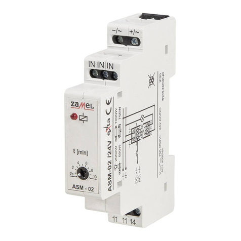
Other Zamel Timer manuals

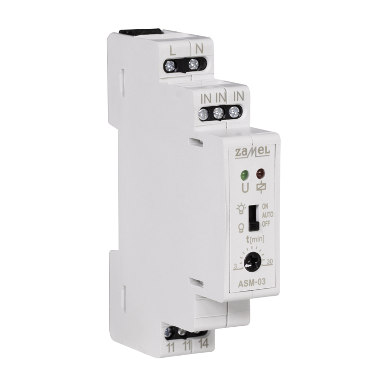
Zamel EXTA ASM-03 User manual

Zamel

Zamel EXTA ASM-03 User manual

Zamel exta ZCM-32 User manual

Zamel

Zamel exta ZCM-32 User manual

Zamel EXTA ASN-02 User manual

Zamel

Zamel EXTA ASN-02 User manual

Zamel EXTA ASM-02 User manual

Zamel

Zamel EXTA ASM-02 User manual

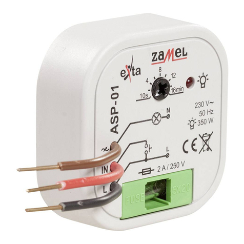
Zamel EXTA ASP-01 User manual

Zamel

Zamel EXTA ASP-01 User manual

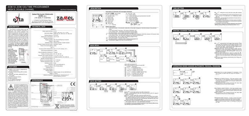
Zamel exta ZCM-12 User manual

Zamel

Zamel exta ZCM-12 User manual

Zamel EXTA ASH-01 User manual

Zamel

Zamel EXTA ASH-01 User manual

Zamel EXTA ASH-02 User manual

Zamel

Zamel EXTA ASH-02 User manual

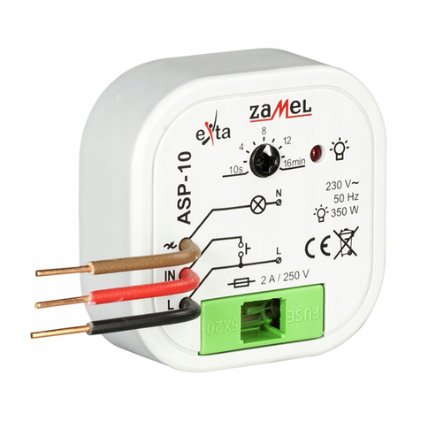
Zamel exta ASP - 10 User manual

Zamel

Zamel exta ASP - 10 User manual

Zamel EXTA ASH-01 User manual

Zamel

Zamel EXTA ASH-01 User manual

Zamel EXTA ASH-02 User manual

Zamel

Zamel EXTA ASH-02 User manual

Popular Timer manuals by other brands

EOS Excellent Installation and operating instruction

EOS

EOS Excellent Installation and operating instruction

Orbegozo PG 10 instructions

Orbegozo

Orbegozo PG 10 instructions

Orbit B-hyve quick start guide

Orbit

Orbit B-hyve quick start guide

Masterplug 7 Day Electronic Timer - Compact User information

Masterplug

Masterplug 7 Day Electronic Timer - Compact User information

Melnor Aqua Timer 3015 manual

Melnor

Melnor Aqua Timer 3015 manual

Auber Instruments JSL-72 instruction manual

Auber Instruments

Auber Instruments JSL-72 instruction manual

Sealey TL2000 instructions

Sealey

Sealey TL2000 instructions

IDEC GT3W Series instructions

IDEC

IDEC GT3W Series instructions

Topgreener TGT09 installation instructions

Topgreener

Topgreener TGT09 installation instructions

Newlec 2747530 Technical description

Newlec

Newlec 2747530 Technical description

Kärcher WT 4 Original instructions

Kärcher

Kärcher WT 4 Original instructions

Roto ZEL STG ZSU 24V manual

Roto

Roto ZEL STG ZSU 24V manual

SEBSON D1 manual

SEBSON

SEBSON D1 manual

Rain Bird SST-400i Operation manual

Rain Bird

Rain Bird SST-400i Operation manual

Diivoo WT-04 user manual

Diivoo

Diivoo WT-04 user manual

Intermatic EH10 installation instructions

Intermatic

Intermatic EH10 installation instructions

DAPAudio IPS-WPT manual

DAPAudio

DAPAudio IPS-WPT manual

CARLO GAVAZZI DAA01 installation instructions

CARLO GAVAZZI

CARLO GAVAZZI DAA01 installation instructions

manuals.online logo
manuals.online logoBrands
  • About & Mission
  • Contact us
  • Privacy Policy
  • Terms and Conditions

Copyright 2025 Manuals.Online. All Rights Reserved.