4
Now bring all magnets one by one under the sensor and check for Magnet
reflector alignment as explained above. The LED on sensor should light up.
Adjust the height of sensor or level of reflector assembly as required till LED
on the sensor lights up for all the reflector assemblies uniformly.
(Red LED for 12V DC & White LED for 24V DC)
Now remove one tape from the reflector assembly and run the Loom at
normal speed. The LED on top of sensor should light up continuously. If it
does not light, check the alignment and then refer to trouble shooting Section.
Now your sensor is ready and can be put to normal operation. Run the
loom at normal speed and when the weft tape breaks or if there is uneven
tension in shuttle bobbin tape, the loom will stop instantly (poor winding on
bobbin or shuttle brake is loose or if the bobbin is empty). The sensor does not
require any maintenance as it is dust proof, but periodic checking will help in
long way. Maintenance and alignment / setting of magnet reflectors are
required to be done periodically.
Precautions: Following precautions will help in getting maximum advantage
from sensor.
a. The sensor will trigger even if the weft tension is low. Ensure that a proper
spring is put in shuttle brake. The weft tension is reduced when the bobbin
diameter is reduced. If sensor triggers at small diameter, then reverse the
bobbin direction to get more tension in weft.
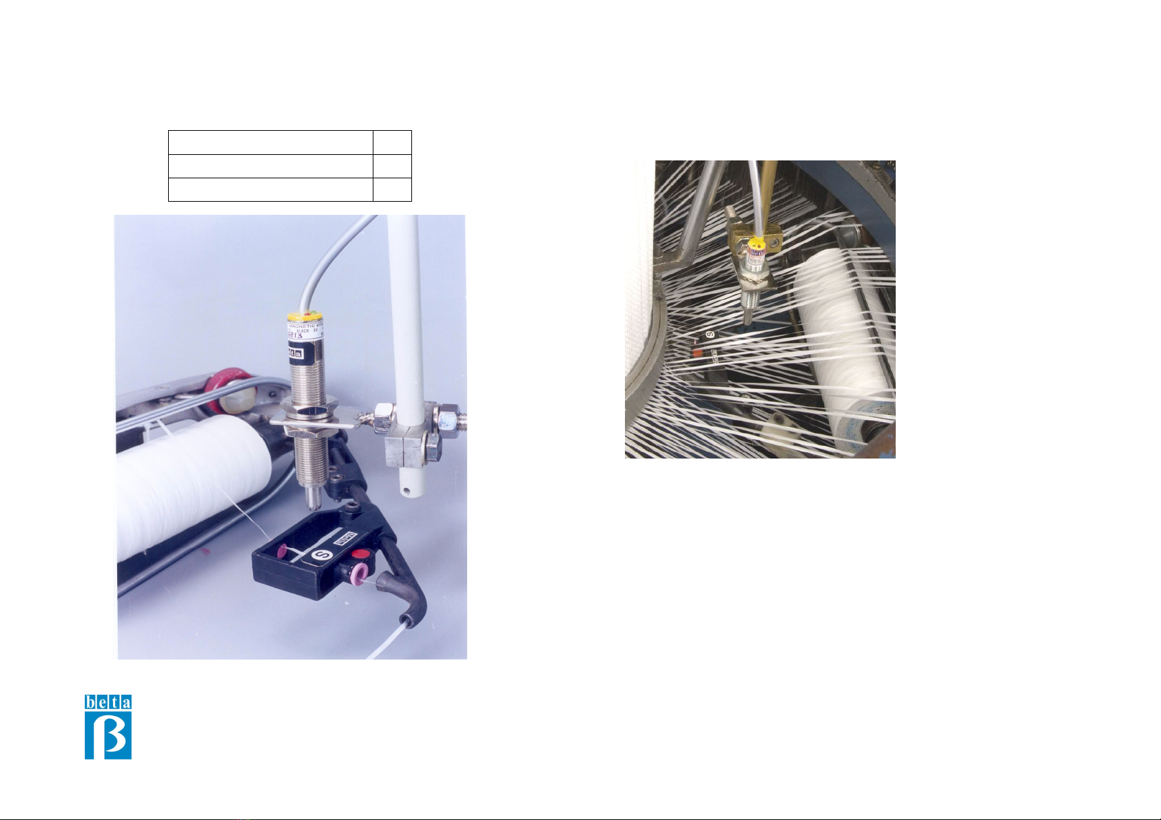
b. The magnet reflector assembly must be tight on boom pipe. The location of
all the assemblies should be same for all the shuttles. Further, these should be
in perfect horizontal position. The gap between sensor tip and magnet should
be around 35 mm and horizontal offset of 10 mm from magnet is desirable to
avoid false tripping.
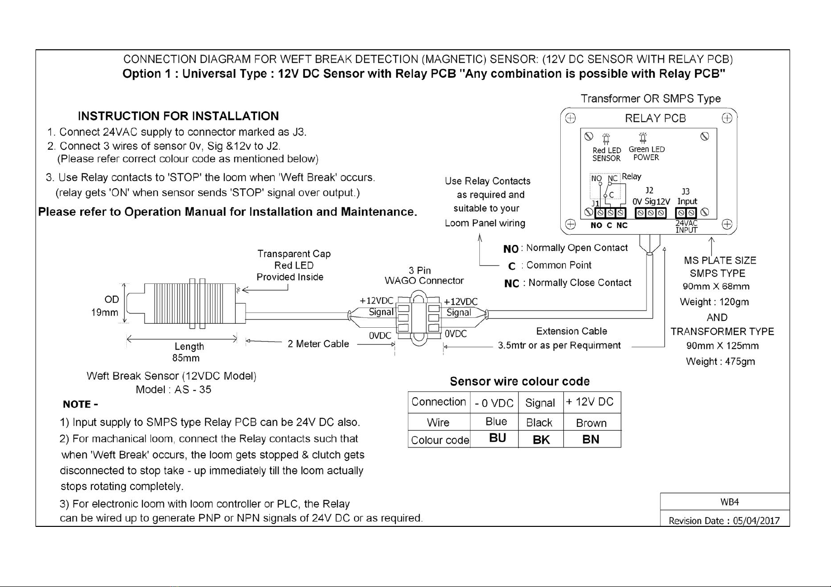
c. For 12V DC Sensor: Do not connect output of sensor to any other PCB.
This may damage electronics inside the sensor. Our sensor is designed for our
relay board only. In case you wish to use any other card, please take prior
permission from our service department.
5
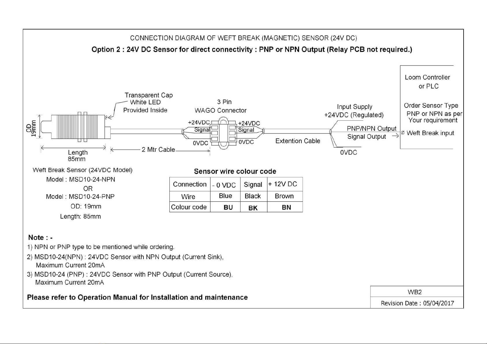
d. For 24V DC Sensor: The Sensor output is PNP type or NPN type. While
ordering, you have to order as per your requirement. This PNP or NPN output
is designed for connecting to loom controller or PLC as digital input only.
e. We have supplied two / three red colour and two / three blue colour magnet
holders with this set. Please mount these alternately on the loom to avoid
Magnetization of sensors in long run.
f. It is highly recommended that yarn path from shuttle bobbin to magnetic
holder and ceramic eyelet on boom pipe should be as straight as possible by
selecting the proper boom pipe size. This will reduce the wear and tear on
boom reflector assembly and give a longer life to it.
LED Indicators:
SELF TEST: A feature is added to check tripping circuit of Weft Break sensor
and LEDs. On every power ON to Weft Break sensor, the LED will flash. This
flashing on power ON indicates that sensor is working and while the LED is on
sensor is ON for a short time, in effect the input on loom controller / PLC will
be also ON at that moment OR the Relay on Relay PCB will be also ON at that
moment. This is the 'self test' by Weft Break sensor where it checks the LED
on sensor, and the output connection of sensor up to Relay PCB OR the loom
controller / PLC is ok.
For 12V DC Sensor Model AS - 35:
The Sensor has one LED and its function is as under:
a. Red LED - Magnetic field sensed by sensor (Tape break condition)
b. The Relay PCB has two LEDs and their functions are as under:
i. Red LED - Relay ON. (Relay gets ON when tape breaks.)
ii. Green LED - Power ON (Always ON when Power supply is ON)
For 24V DC Sensor:
The Sensor has one LED and its function is as under:
White LED - Magnetic field sensed by sensor (Tape break condition)