Better Bathrooms 900 Quadrant Steam User manual

900 Quadrant Steam
Shower Cabin with 6 Body Jets
PLEASE READ THE GUIDE BEFORE COMMENCING INSTALLATION
Please retain this document for future reference
Multiple person assembly
BUY IT DIRECT
Lowfields Way
Elland
Hx5 9DA
This product is IPX4 rated, and so no part of the installation
is allowed to be within bathroom Zones 0 or 1. Installation is
permitted within Zone 2
and outside of the bathroom zones as long as it is not in a
position where it is likely to be sprayed with water.
Zone 0: The interior of the bathtub or shower basin.
Zone 1: The area around the bathtub or shower basin
up to a height of 2.25m above the floor
Zone 2: The area stretching to 0.6m outside the bath or
shower and above the bath or shower if over 2.25m

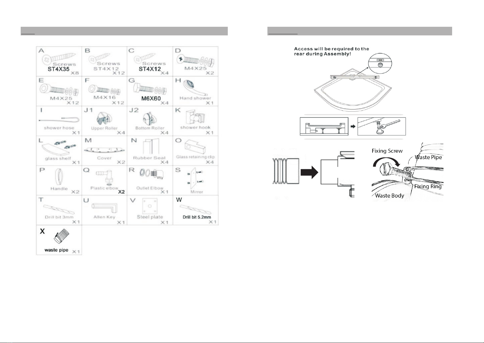
Information (Electrical work to be carried out by a Qualified Electrician) Parts
> This installation is a multiple person installation
> Ensure the glass is not chipped or cracked before installation
> AC Power supply of 220V + 10% 50 Hz which should be connected to
to an earthed 13amp fused spur switch, outside the bathroom.
> Supply wiring to the unit should be no less than 4mm2
> Water supply pressure 1.5 - 4 bar
> The hot water supply should not exceed 65c
> The water supply pipes should be fitted with isolation valves and
be located to allow easy access.
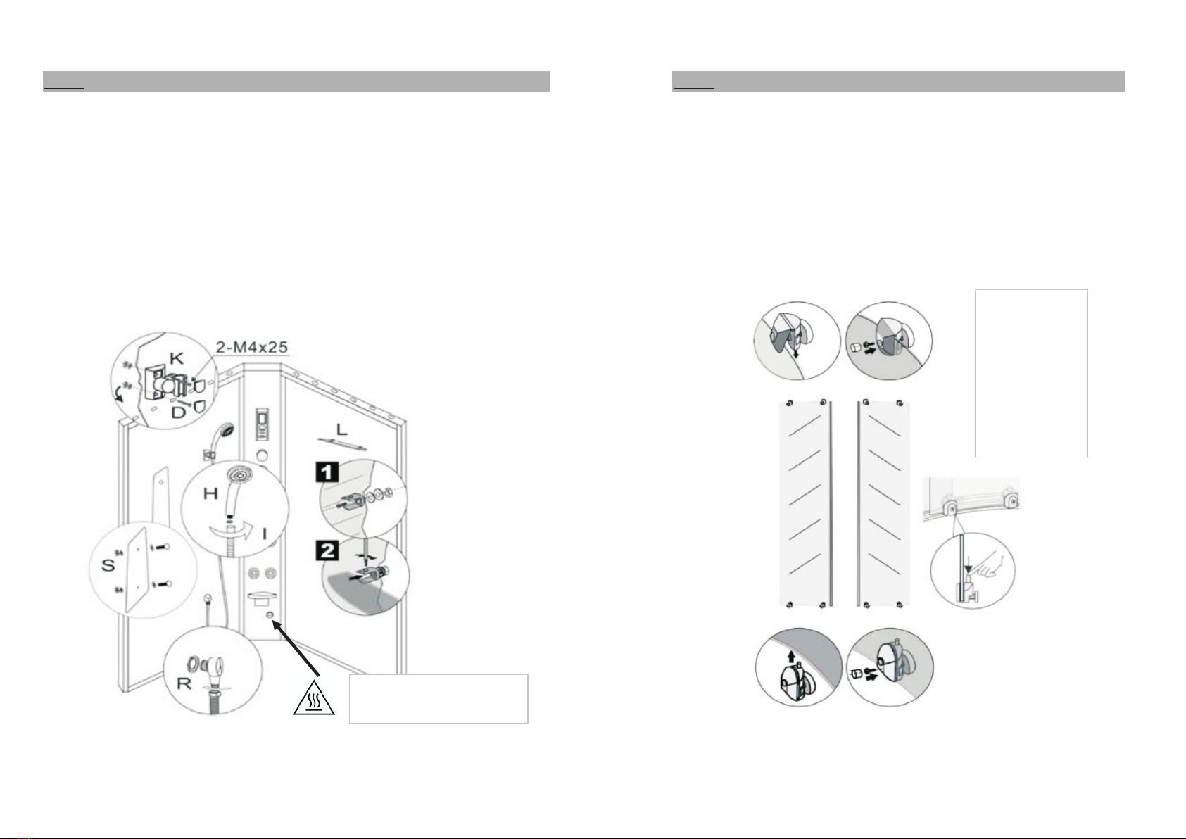
> The steam generator and steam outlet become hot during use and
remain hot for a period after use, therefore contact with either can
cause injury, do not touch until fully cooled.
> After use always turn off the unit at the switch.
> Any maintenance should only be carried out once the power supply
to the unit has been isolated
> Any maintenance should only be carried out once the water supply
to the unit has been isolated
> Separate electrical appliances producing steam or humidity are not to be used
inside the cabin.
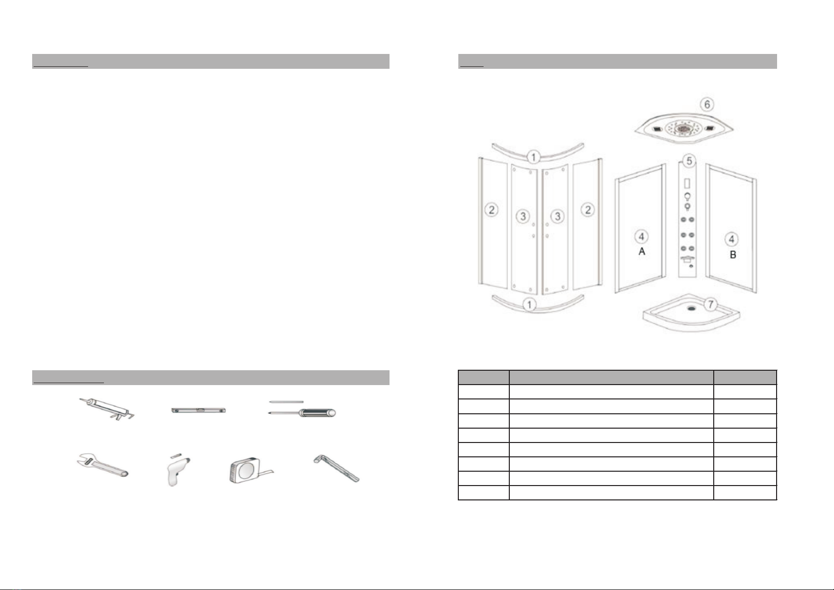
Tools Required No Description Qty
No.1 Chrome rail 2
No.2 Fixed panel 2
No.3 Door 2
Silicone Sealant Spirit Level Screwdriver No.4A Shower kit black back panel 1
No.4B Shelf black back panel 1
No. 5 Control panel inc steam box & electrics 1
No.6 Roof - inc speaker, fan and lights 1
Spanner Drill Tape Measure Hex Key No.7 Tray inc waste 1
SEPT 18 - V6BB

Parts Tray Install
! Check for removal of any protective film/tape
Before installatiing the tray, connect the waste pipe (X) and fixing ring
to the waste body, once connected tighten the ring using the screw.
Place the tray inc waste into the required location
Once in position check the tray is level
If levelling is required, adjust the legs on the tray
Check the tray using a spirit level
Once the tray is level, tighten the securing nuts on the legs
After levelling, connect the pre-fitted waste tube to the
Check all parts are present before commencing the installation household waste pipe using an adequate sealing method.
Check for leaks before continuing the installation
Also check sufficient fall is provided for the waste pipe
Waste Pipe
Waste
SEPT 18 - V6BB

Install (Multiple person assembly) Install
1. Connect the top and bottom rails (1) to the fixed panels (2) 4. Push seal (N) onto the edge of the fixed panel (2)
2. Hold the rail (1) to the front face of the chrome profile (2) 5. Ensure the fin on the seal faces inside the enclosure
3. From inside the profile connect the screws (A) and tighten into rail 6. Fit the glass clips (O) to the rail using screws (C)
7. Ensure clips are secure to retain the fixed glass
Note: Seals may require trimming to size
SEPT 18 - V6BB

Install (Multiple person assembly) Install
8. You must seal the frame as shown below, along the length of the 9. Attach the top and bottom covers (M) to the end of the
touching surfaces (Do not seal on the inside) central panel (5)
10. Push the back panels (4A and 4B) to the central panel (5)
after being sealed and align correctly.
11. Secure together using the nuts and bolts (F)
! Failure to seal in this way may allow water to escape through the
touching surfaces and to the outside of the enclosure.
SEPT 18 - V6BB

Install (Multiple person assembly) Install
12. Place the panel assembly onto the tray and align frame with tray. 15. Remove assembly, drill holes using 5.2mm drill bit (supplied)
13. Place the steel plate (V) onto the back corner of the tray (Drill should not be on hammer setting)
14. Align the steam generator to the steel plate, once steam generator Hold this frame and secure into position using the fixings
and frame are aligned, mark drill holes onto tray. provided, as shown below.
Hot surface during use
The corner profile
should have the cut out
positioned over the lip
on the tray
SEPT 18 - V6BB

Install (Multiple person assembly) Install
17. Place the front frame and glass onto the tray and align on the 18. Seal the frame as shown, before connecting the front frame to the
tray and with the back panels, drill frame using a 3mm drill bit. back panels and to the tray.
Remove the assembly. ! Failure to seal in this way may allow water to escape through the
touching surfaces and to the outside of the enclosure.
Align assembly on the tray to
position frame holes over drilled
holes in tray
When sealing between the frame
and tray ensure to seal up to the
drainage slot in the tray, do not
block the drainage slot.
SEPT 18 - V6BB

Install (Multiple person assembly) Install
19. Place the roof (6) onto the assembly and secure to the frame using 21. Secure the steam generator frame to the steel plate (V) using
fixings provided nuts and bolts (G)
20. Connect flexi-tube from mixer to shower head connection, 22. Insert steam generator hose through centre hole in plate (V)and
ensure seal is fitted and tighten connect to outlet on shower waste (Pic 6)
SEPT 18 - V6BB

Install (Multiple person assembly) Install
23. To connect the mixer to the water supply, you will require 27. Seal the outside of the enclosure, along the front edge
2 x flexi connectors with 1/2" female nut (not supplied) where any touching surfaces meet.
24. When looking at the front of the enclosure the hot supply 28. Seal along the back and side edges where the frame
must be connected to the left inlet, failure to do this will meets the tray, ensuring not block the drainage slots
cause issues with the thermostat function
25. When installing the flexi-tails do not create flat spots, DO NOT SEAL INSIDE
kinks or bend excessively as this could result in damage to
the tail and affect performance. DO NOT USE FOR AT LEAST 24 HOURS
26. Turn on water supply and check for leaks
Front
Hot surface
Flexi-pipes not supplied Rear Steam generator
SEPT 18 - V6BB

Install (Multiple person assembly) Install
30. Connect handset holder (K) to the left hand back panel 35. Fit fixed roller (J1) to top of each glass door, secure and fit
tighten and secure using fixings (D), do not overtighten cover
31. Connect mirror (S) to left hand back panel 36. Fit spring bottom rollers (J2) to bottom of each glass door,
32. Connect hose outlet (R) to left hand back panel using nut secure and fit cover
provided, with thread for hose facing down 37, Hook the door onto the top rail, push the door towards the
33. Attach fixings for shelf to right hand back panel and secure, bottom rail, then press down on the bottom roller to hook
then slide the glass into the brackets and secure using under the bottom rail, then release.
retaining screws within the brackets 38. Push vertical door seals (N) onto back edge of door, cut if
34. Connect shower hose to outlet (R) and handset (H) required
ensuring to fit seals (cone end to fit inside holder K) If adjustment
in the doors is
required, do
this by turning
the
adjustment
screw in the
top roller
Hot Surface - Steam
Outlet
SEPT 18 - V6BB
Table of contents
Other Better Bathrooms Shower Cabin manuals
Popular Shower Cabin manuals by other brands

US HORIZON
US HORIZON SORRENTO Series Assembly instructions

Arblu
Arblu PERSEO ANGOLO Q-R 2SL+1LF Assembling instructions

ELEGANT
ELEGANT SPR870 quick start guide

RIHO
RIHO SCANDIC NXT X101 installation manual

Aquadart
Aquadart Rolla 8 installation instructions

Arblu
Arblu DEDALO PLUS NICCHIA 1AB+1LF Assembly instructions


