Beuchat VOYAGER-2G User manual


2
LIMITED TWO-YEAR WARRANTY
For details, refer to the Product Warranty Registration Card provided.
COPYRIGHT NOTICE
This manual is copyrighted, all rights are reserved. It may not, in whole or in part, be copied, photocopied, repro-
duced, translated, or reduced to any electronic medium or machine readable form without prior consent in writing from
Beuchat/2002 Design.
VOYAGER 2G Operating Manual, Doc. No. 12-2792
©2002 Design, 2010
San Leandro, CA USA 94577
TRADEMARK NOTICE
Beuchat, the Beuchat Logo, VOYAGER 2G, and the VOYAGER 2G Logo, are all registered and unregistered trademarks
of Beuchat. All rights are reserved.
PATENT NOTICE
U.S. Patents have been issued, or applied for, to protect the following design features:
Data Sensing and Processing Device (U.S. Patent no. 4,882,678), Ascent Rate Indicator (U.S. Patent no. 5,156,055).
CE
The CE mark is used to mark conformity with the European Union EMC directive 89/336/EEC. Beuchat dive instru-
ments fulfill the required EU directives.
EN 13319 "Diving accessories - Depth gauges and combined depth and time measuring devices - Functional and
safety requirements, test methods" is a European diving depth gauge standard. The VOYAGER 2G is designed to
comply with this standard.
DECOMPRESSION MODEL
The program within the VOYAGER 2G simulates the absorption of nitrogen into the body by using a mathematical
model. This model is merely a way to apply a limited set of data to a large range of experiences. The VOYAGER 2G
dive computer model is based upon the latest research and experiments in decompression theory. Still, using the
VOYAGER 2G, just as using the Navy (or other) No Decompression Tables, is no guarantee of avoid-
ing decompression sickness, i.e. “the bends.” Every diver’s physiology is different, and can even vary from
day to day. No machine can predict how your body will react to a particular dive profile.

3
CONTENTS
WARRANTY, NOTICES, DECOMPRESSION MODEL ....................................................................................................2
OVERVIEW .......................................................................................................................................................................7
FULL LCD ....................................................................................................................................................................8
CONTROL BUTTONS .................................................................................................................................................9
OPERATING MODES ................................................................................................................................................10
AUDIBLE ALARM .....................................................................................................................................................10
BACKLIGHT ..............................................................................................................................................................12
POWER SUPPLY.......................................................................................................................................................13
PC INTERFACE .........................................................................................................................................................14
FEATURES AND DISPLAYS ..........................................................................................................................................15
BAR GRAPHS ...........................................................................................................................................................16
ALPHA / NUMERIC DISPLAYS ...............................................................................................................................18
SURFACE MODES .........................................................................................................................................................21
OPERATING MODES AND SURFACE MODE .........................................................................................................22
NORM SURF MAIN and ALTs ..............................................................................................................................23
NORM/GAUGE SET MODES ....................................................................................................................................24
SET F (NORM FO2) ...................................................................................................................................................25
Set FO2 GAS 1 .....................................................................................................................................................26
Set FO2 GAS 2 .....................................................................................................................................................27
Set FO2 Default ....................................................................................................................................................28

4
CONTENTS (continued)
SET A (NORM/GAUG ALARMS) ..............................................................................................................................28
Set Audible Alarm .................................................................................................................................................28
Set Depth Alarm....................................................................................................................................................39
Set EDT (Elapsed Dive Time) Alarm ....................................................................................................................39
Set NiBG (Nitrogen Bar Graph) Alarm ..................................................................................................................30
Set DTR (Dive Time Remaining) Alarm ................................................................................................................30
Set PO2 Alarm .....................................................................................................................................................30
SET U (UTILITIES) ....................................................................................................................................................31
Set Wet Activation .................................................................................................................................................31
Set Units ...............................................................................................................................................................31
Set DS (Deep Stop) ..............................................................................................................................................32
Set SS (Safety Stop).............................................................................................................................................32
Set CF (Conservative Factor) ...............................................................................................................................32
Set Glo (Backlight Duration) .................................................................................................................................33
Set SR (Sampling Rate) .......................................................................................................................................33
SET T (TIME) .............................................................................................................................................................34
Set Date Format ...................................................................................................................................................34
Set Time Format ...................................................................................................................................................34
Set Time................................................................................................................................................................35
Set Date ................................................................................................................................................................35
SN (SERIAL NUMBER) .............................................................................................................................................36
DIVE PLANNER (NORM) ..........................................................................................................................................37
FLY COUNTDOWN (NORM/GAUG) .........................................................................................................................39
DESAT COUNTDOWN (NORM) ................................................................................................................................39
MEMO MODE (NORM/GAUG) ..................................................................................................................................40
HISTORICAL MODE (NORM/GAUG) .......................................................................................................................43

5
CONTENTS (continued)
NORM DIVE MODES ......................................................................................................................................................45
NO DECO DIVE TIME REMAINING (NDC) ...............................................................................................................46
OXYGEN ACCUMULATION ......................................................................................................................................46
ASCENT RATE INDICATOR (ASC) ..........................................................................................................................47
NO DECO DIVE MODE .............................................................................................................................................47
No Deco Deep Stop (DS) .....................................................................................................................................49
No Deco Safety Stop (SS) ....................................................................................................................................51
CAUTIONARY MODES ...................................................................................................................................................53
DECOMPRESSION ...................................................................................................................................................54
CONDITIONAL VIOLATION (CV)..............................................................................................................................56
DELAYED VIOLATION 1 (DV1) .................................................................................................................................57
DELAYED VIOLATION 2 (DV2) .................................................................................................................................58
DELAYED VIOLATION 3 (DV3) .................................................................................................................................59
VIOLATION GAUGE MODE (VGM) ..........................................................................................................................60
HIGH PO2 ..................................................................................................................................................................62
HIGH O2 ...................................................................................................................................................................63
SWITCHING GAS MIXES (NORM) .................................................................................................................................65
NORM POST DIVE MODES ...........................................................................................................................................69
FIRST 10 MINUTES ON SURFACE ..........................................................................................................................70
AFTER 10 MINUTES ON SURFACE ........................................................................................................................71
UPLOADING SETTINGS AND DOWNLOADING DATA ...........................................................................................72
GAUGE OPERATING MODE (GAUG) ...........................................................................................................................73
DIGITAL GAUGE MODE ...........................................................................................................................................74

6
CONTENTS (continued)
FREE DIVE OPERATING MODE ....................................................................................................................................77
COUNTDOWN TIMER (CDT) ....................................................................................................................................80
ELAPSED DIVE TIME (EDT) ALARM .......................................................................................................................81
DEPTH ALARMS (DAs) ............................................................................................................................................82
FREE DIVE MAIN AND ALTs ....................................................................................................................................83
FREE DIVE ALARMS ................................................................................................................................................84
GENERAL .......................................................................................................................................................................89
CARE AND CLEANING.............................................................................................................................................90
INSPECTIONS AND SERVICE .................................................................................................................................91
BATTERY REPLACEMENT ......................................................................................................................................92
ALTITUDE SENSING AND ADJUSTMENT ..............................................................................................................97
CHART OF OXYGEN EXPOSURE LIMITS ..............................................................................................................98
CHARTS OF NDLS AT ALTITUDE ............................................................................................................................99
SPECIFICATIONS ...................................................................................................................................................100
INSPECTION/ SERVICE RECORD .........................................................................................................................105

7
OVERVIEW

8
FULL LCD
Components:
a. Icon - Low Battery
b. Icon - Gas # (mix)
c. O2BG (O2 Bar Graph)
d. Icon - Degrees
e. Icon - Max/Depth
f. Icon - Stop
g. Icon - Memo Mode
h. Icon - Alarm
i. NiBG (Nitrogen Bar Graph)
j. Icon - Plan mode
k. Icon - Altitude
l. Icon - Ascent Rate
m. Icon - Depth/Max Depth
n. Time to Surface
o. Icon - Time of Day
p. Ascent Rate Indicator
q. Icon - Deco Stop Time Required
No Deco Time Remaining
Elapsed Dive Time
r. Icon - O2 Time
s. Icon - % O2
p
s
f
l
i
b
a
r
m
g
o
d
e
h
jk
n
q
c

9
INTRODUCTION
Welcome to Beuchat and thank you for choosing the VOYAGER 2G !
It is extremely important that you read this Operating Manual in sequence and understand
it completely before attempting to use the VOYAGER 2G as a dive computer.
Remember that technology is no substitute for common sense, and a dive computer only
provides the person using it with data, not the knowledge to use it.
CONTROL BUTTONS
The VOYAGER 2G features three Control Buttons that allow you to select mode options
and access specific information. They are also used to enter Settings, activate the Back-
light, and acknowledge the Audible Alarm.
Throughout this manual they will be referred to as the M, A, and S buttons.
• Front/Left - Mode (M) button
• Front/Right - Advance (A) button
• Right/Side - Select (S) button
M A
S

10
Fig. 2 - FREE MODE
Fig. 1B - GAUG MODE
Fig. 1A - NORM MODE
OPERATING MODES
The VOYAGER 2G features 3 Operating Modes, NORM (Fig.
1A) which is used for Air and Nitrox SCUBA dives, GAUG (Fig.
1B) used for SCUBA dives in which Nitrogen-Oxygen calcula-
tions are not performed, and FREE (Fig. 2) used for breath hold
activities that do not use SCUBA.
> NORM Mode allows access to Fly, Sat, Memo, and
Historical Modes, as well as entering settings.
> GAUG Mode is similar without access to Sat.
> FREE Mode only allows access to specific Free Modes.
AUDIBLE ALARM
Most warning situations that activate the Audible Alarm while
operating in NORM or GAUG Mode cause the VOYAGER 2G
to emit 1 beep per second for 10 seconds, or until the situation
is corrected, or it is acknowledged by momentarily pressing and
releasing the S button (less than 2 seconds).
After being acknowledged and the situation corrected, the
Alarm will sound again upon reentry into the warning situation,
or entry into another type of warning situation.
FREE Mode has its own set of Alarms which emit 3 short beeps
either 1 or 3 times which cannot be acknowledged or set Off.

11
Situations that will activate the NORM/GAUG 10 second Alarm include -
• Descent deeper than the Depth value set.
• Dive Time Remaining decreases to the value set.
• Elapsed Dive Time reaches to the value set.
• PO2 reaches to the value set.
• O2 reaches 300 OTU (max single or daily exposure allowed).
• Nitrogen Bar Graph reaches the segment value set.
• NORM/GAUG Ascent Rate exceeds 18 MPM (60 FPM) when deeper than 18 M (60
FT), or 9 MPM (30 FPM) at 18 M (60 FT) and shallower.
• Entry into Decompression Mode (Deco).
• Conditional Violation (above a required Deco Stop Depth < 5 minutes).
• Delayed Violation (above a required Deco Stop Depth => 5 minutes).
• Delayed Violation (Deco requires a Stop Depth > 18 M/60 FT).
• Delayed Violation (descent deeper than the Max Operating Depth of 100 M/330 FT
in NORM, or 120 M/399 FT in GAUG).
• A Gas Switch would expose the diver to PO2 greater than 1,60 ATA.
A single short beep (which cannot be disabled) is emitted for the following -
• Upon completion of a battery change.
• Change from Delayed to Full Violation 5 minutes after the dive.
3 short beeps (which cannot be disabled) are emitted for the following -
• NORM/GAUG Ascent Rate is 15,1 to 18 MPM (51 to 60 FPM) when deeper than
18 M (60 FT), or 7,5 to 9 MPM (26 to 30 FPM) at 18 M (60 FT) and shallower.
• FREE Dive Elapsed Dive Time Alarm (3 beeps every 30 seconds if set On).
• FREE Dive Depth Alarms 1/2/3 (set sequentially deeper) - each 3 beeps 3 times.

12
• FREE Dive NiBG Alarm (Caution zone, 7 segments) - 3 beeps 3 times.
• Entry into Deco during a FREE Dive (Permanent Violation) - 3 beeps 3 times.
• Free Dive Mode Countdown Timer reaches 0:00 - each 3 beeps 3 times.
During the following NORM Dive situations, the 10 second continuous tone will be fol-
lowed by a 5 second steady beep that will not turn off when acknowledged -
• Ascending above a required Decompression Stop Depth for more than 5 minutes
(referred to as a Delayed Violation).
• Decompression requires a Stop Depth of 70 FT/21 M or deeper.
• Being on the Surface for 5 minutes after a Conditional Violation.
BACKLIGHT
> To activate the Backlight, while on the surface and during dives >> depress the S
button for 2 seconds.
• The Backlight will illuminate the display for button depression time plus the Duration
time set 0 , 5 , or 10 seconds.
*The Backlight will turn Off if the button is held depressed for more than 10 seconds.
• Press the button again to activate as desired.
NOTE: Extensive use of the Backlight reduces estimated Battery life.
Also, the Backlight does not operate during a Low Battery Condition
or when the VOYAGER 2G is connected to a PC.

13
Fig. 4 - LOW BATTERY
ALARM
Fig. 3 - LOW BATTERY
WARNING
a
a
POWER SUPPLY
The VOYAGER 2G uses (1) 3 volt CR2450 Lithium Battery which
should maintain operation for 1 year or 300 dive hours if 2
dives are conducted during each dive period. The VOYAGER
2G checks battery voltage every 2 minutes while on the surface.
• If voltage of the VOYAGER 2G decreases to the Warning
level (2,75 volts), the Battery icon will appear on Surface
display screens (Fig. 3a) as an indication that the Battery
should be changed prior to commencing a series of dives.
• If voltage decreases to the Alarm level (2,50 volts), the
graphics CHG and bAt will alternate in place of NOR, and
the Battery icon will flash, (Fig. 4) for 5 seconds then the
unit will shut Off.
• Low Battery conditions are not displayed during dives. If a
Low Battery condition was not displayed prior to starting a
Dive, and a Low Battery Condition occurs during the dive,
there will be sufficient Battery power remaining to maintain
operation for the remainder of that dive.
• Upon surfacing, the Low Battery icon will be displayed with
warning or alarm indication as described above.

14
PC INTERFACE
Interface with a PC (for data Upload and Download) is accom-
plished by connecting the VOYAGER 2G to a PC USB Port using
the special USB Interface Cable available as an option.
The PC Interface program and a USB Driver are provided on
the product CD. The Help portion serves as the program's
user manual and can be printed for personal use. The settings
upload portion is used to check the VOYAGER 2G's existing
settings and for entering Time, Alarm, and other settings into the
VOYAGER 2G. The download portion is used to retrieve data
that was sampled during dives and stored in the VOYAGER
2G's memory.
The VOYAGER 2G checks for an external access request once
every second while in Surface Mode. Checks are not made if
the unit is wet. For a connection to be made, the interface cable
is connected to the VOYAGER 2G's Data Port and plugged into
a PC USB port. To establish the connection, the PC program
must be running.
When the connection is made, a PC screen appears on the VOY-
AGER 2G (Fig. 5) displaying the graphic PC and a countdown
for 2 minutes or until completion of the interface operation.
Then operation reverts to the Surface Main screen.
Fig. 5 - PC
(during upload/download)

15
FEATURES AND DISPLAYS
16
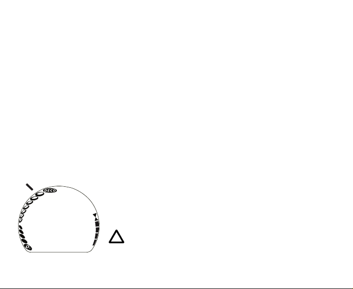
BAR GRAPHS
The VOYAGER 2G features 3 Bar Graphs >> NiBG, O2BG,
and ASC.
NiBG (Nitrogen Loading Bar Graph)
The NiBG (Fig. 6a) represents tissue loading of nitrogen, show-
ing your relative no decompression or decompression status. As
your depth and elapsed dive time increase, segments will add to
the NiBG, and as you ascend to shallower depths, the segments
will recede, indicating that additional no decompression time is
allowed for multilevel diving.
The NiBG monitors 12 different nitrogen compartments simulta-
neously and displays the one that is in control of your dive. It
is divided into a No Deco zone (lower 6 segments), a Caution
zone (7th segment), and a Deco (danger) zone (top segment).
While you cannot provide a guarantee against the occurrence
of decompression sickness, you may choose your own personal
zone of caution based upon age, physique, excessive weight,
etc., to reduce the statistical risk.
NOTE: Displays associated with oxygen and the
O2BG will only appear if FO2 has been set at a
value other than 'Air' (e.g., a numerical value).
Fig. 6 - NiBG
a

17
O2BG (Oxygen Bar Graph)
The O2BG (Fig. 7a) represents oxygen loading, showing the
maximum of either per dive accumulated oxygen, or 24 hour
period accumulated oxygen.
As your oxygen exposure (accumulation) increases during the
dive, segments will add to the O2BG, and as saturation decreas-
es, it will begin to recede indicating that additional exposure is
allowed for that dive and 24 hour period.
ASC (Ascent Rate Indicator)
The ASC (Fig. 7b) provides a visual representation of ascent
speed (i.e., an ascent speedometer).
The segments of the ASC represent two sets of speeds which
change at a reference Depth of 18 M (60 FT). Refer to the chart
for segment values.
WARNING: At depths greater than 18 M (60 FT),
ascent rates should not exceed 18 meters per
minute (60 feet per minute). At depths of 18 M
(60 FT) and shallower, ascent rates should not
exceed 9 meters per minute (30 feet per min-
ute).
ASC values
Deeper than 18 M (60 FT)
Segments Ascent Rate =
Displayed MPM FPM
0 0 - 6 0 - 20
1 6.5 - 9 21 - 30
2 9.5 - 12 31 - 40
3 12.5 - 15 41 - 50
4 15.5 - 18 51 - 60
5 > 18 > 60
18 M (60 FT) & Shallower
Segments Ascent Rate =
Displayed MPM FPM
0 0 - 3 0 - 10
1 3.5 - 4.5 11 - 15
2 5 - 6 16 - 20
3 6.5 - 7.5 21 - 25
4 8 - 9 26 - 30
5 > 9 > 30
Fig. 7 - O2BG & ASC
a
b
18
ALPHA/NUMERIC DISPLAYS
Each numeric and graphic display represents a unique piece of
information. It is imperative that you understand the formats,
ranges, and values of the information represented to avoid any
possible misunderstanding that could result in error.
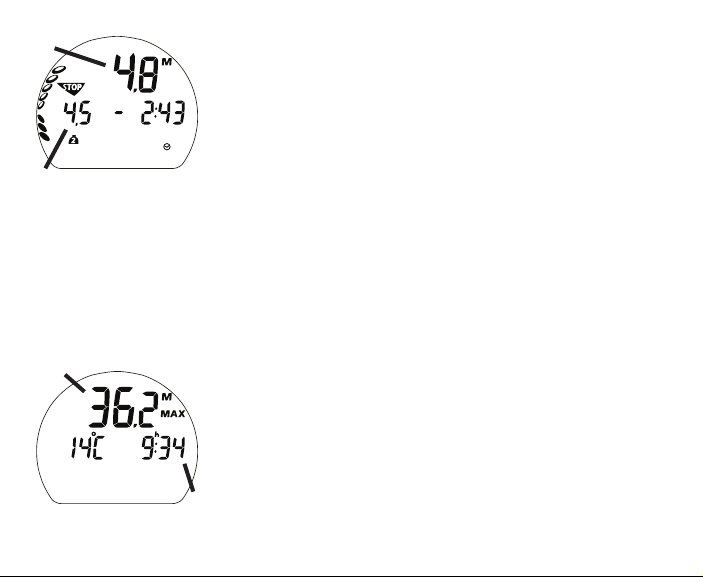
Depth
Current Depth is displayed on the Main Dive screens (Fig. 8a)
with the M (or FT) icon from 0 to 99,9 M (330 FT) in NORM/
FREE, 120 M (399 FT) in GAUG, in increments of 0,1 M (1 FT).
Stop Depths (Deep, Safety, and Deco) are also displayed on the
Main screens (Fig. 8b) when applicable.
Max Depth is displayed on Alternate screens (Fig. 9a) with the
M (or FT) and MAX icons from 0 to 99,9 M (330 FT) in NORM/
FREE, 120 M (399 FT) in GAUG, in increments of 0,1 M (1 FT).
Time and Date
Most Time displays like Time of Day (Fig. 9b) are shown in
hour:minute format (i.e., 9:34 represents 9 hours and 34
minutes, not 934 minutes!). The colon that separates hr:min
(min:sec) blinks once per second when the display is indicating
real time (e.g., Time of Day, Elapsed Dive Time).
Fig. 9 - DIVE ALTERNATE
a
Fig. 8 - DIVE MAIN
(at a Safety Stop)
b
a
b
19
When Times are calculated projections such as NDC (Fig. 10a)
and Elapsed Dive Time (Fig. 10b), the colon is solid.
FREE Dive Mode displays Times in minute:second format.
Date is only displayed in Memo Mode.
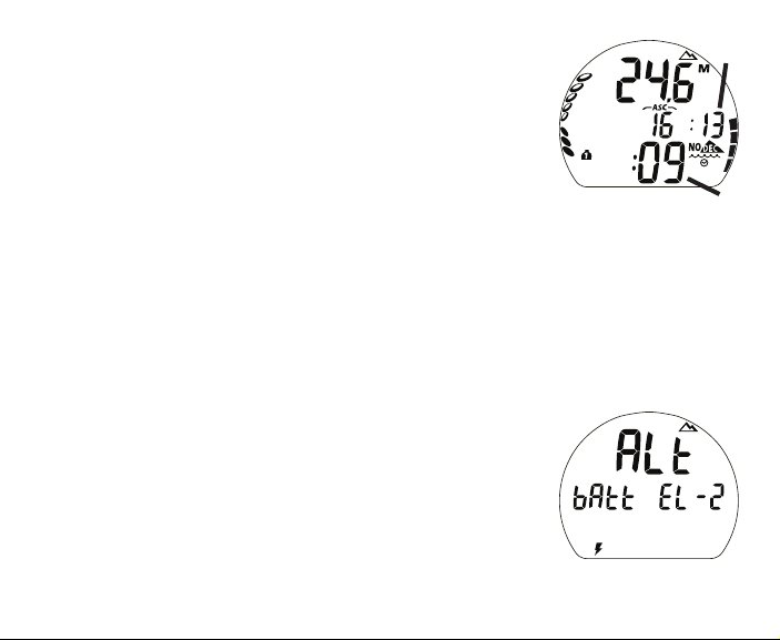
Altitude
When activities are being conducted at elevations higher than
915 meters (3000 feet) , an Altitude (mountain ) icon will be
displayed on Surface and Dive Main screens as an indication
that Depth displays and calculations will be adjusted due to
higher altitude.
The higher Altitude levels (listed below) can be viewed by
accessing a Surface Alternate screen (Fig. 11). While in Dive
Mode, the Altitude icon will be displayed only if it applies.
Sea Level = up to 915 meters (3000 feet)
EL - 2 = 916 to 1525 meters (3001 to 5000 feet)
EL - 3 = 1526 to 2135 meters (5001 to 7000 feet)
EL - 4 = 2136 to 2745 meters (7001 to 9000 feet)
EL - 5 = 2746 to 3355 meters (9001 to 11000 feet)
EL - 6 = 3356 to 3965 meters (11001 to 13000 feet)
EL - 7 = 3966 to 4270 meters (13001 to 14000 feet)
Fig. 11 - SURF ALT 1
(Altitude, Battery status)
a
Fig. 10 - TIMES
(during dive)
b

20
• It should not be considered that the capabilities built into the VOYAGER 2G pro-
vide an implied approval or consent from Beuchat for individuals to exceed the
defined limits for recreational diving, as agreed on by all internationally recog-
nized training agencies.
• The oxygen features of the VOYAGER 2G are intended for use by recreational
divers trained for Nitrox diving by an instructor certified by a recognized training
agency to teach diving with Nitrox.
• Conducting repetitive dives using enriched nitrogen-oxygen mixtures can lead to
oxygen buildup, reducing oxygen tolerance while increasing the risk of pulmo-
nary oxygen toxicity.
• The VOYAGER 2G provides information based upon a personal dive profile, and
therefore must not be shared between divers. It is impossible for two divers to
stay precisely together underwater, and your computer's dive profile tracking of
previous dives will be pertinent to you only. Nitrogen and oxygen loading of a
second user may be significantly different and swapping dive computers could
lead to inaccurate and dangerous predictions of decompression and oxygen ac-
cumulation status.
WARNINGS AND SAFETY RECOMMENDATIONS
Temperature
Ambient Temperature (Fig. 12a) can be viewed by accessing the
Surface ALT 2 or a Dive ALT screen.
Fig. 12 - SURF ALT 2
a
Table of contents
Other Beuchat Watch manuals


