Beveltools Mite EBI-C 3.0 User manual

EN
NL
DE
FR
ES
Instruction manual
Gebruikershandleiding
Betriebsanleitung
Mode d’emploi
Instrucciones de funcionamiento
www.beveltools.com
Bevel Mite®EBI-C 3.0

1
Content
1.1 General notes on safety
1.2 Use of the machine for purposes for which it is intended
1.3 Incorrect use
1.4 CE declaration of conformity
1.5 Symbol legend
2.1 Prior to taking the machine into service
2.2 Taking the machine into service
2.3 Rating data
2.4 Operating conditions
3.1 Protection devices
3.2 Bevel heads
3.3 Operating instructions
4.1 Preventive maintenance
4.2 Repair
4.3 Warranty
4.4 Storage
4.5 Disposal / Environmental compatibility
4.6 Spare parts
EN

2
EN
1.1 General notes on safety
This operation manual is applicable for the machine Bevel Mite®EBI 3.0
safety glasses and ear protection.
WARNING Read all safety warnings and all instructions. Failure to follow the warnings and instructions may result in
1.2 Use of the machine for purposes for which it is intended
The machines are intended for the purpose of milling metal and plastic materials without the use of water. The
and machine building.
1.3 Incorrect use
1.4 CE declaration of conformity
1.5 Symbol legend
Note on safety / Warning
This information serves to achieve safe operation. Failure to observe this information may compromise the operator‘s
safety.
Information
of the operational potential of the product.
Technical Document
Read the technical document prior to commissioning.
Safety glasses and ear protection
Wear safety glasses and ear protection.
Disposal
Friendly-to-the-environment disposal.
Power - Battery Pack
Remove the battery pack before any work is carried out on the machine.
!
i
h
3
2.1 Prior to taking the machine into service
Working with worn or damaged bevel heads will cause the machine to fail.
• Check bevel head prior to use.
• The bevel head must be changed regularly.
• The bevel head must be mounted correctly see 3.2.1
• Observe national regulations.
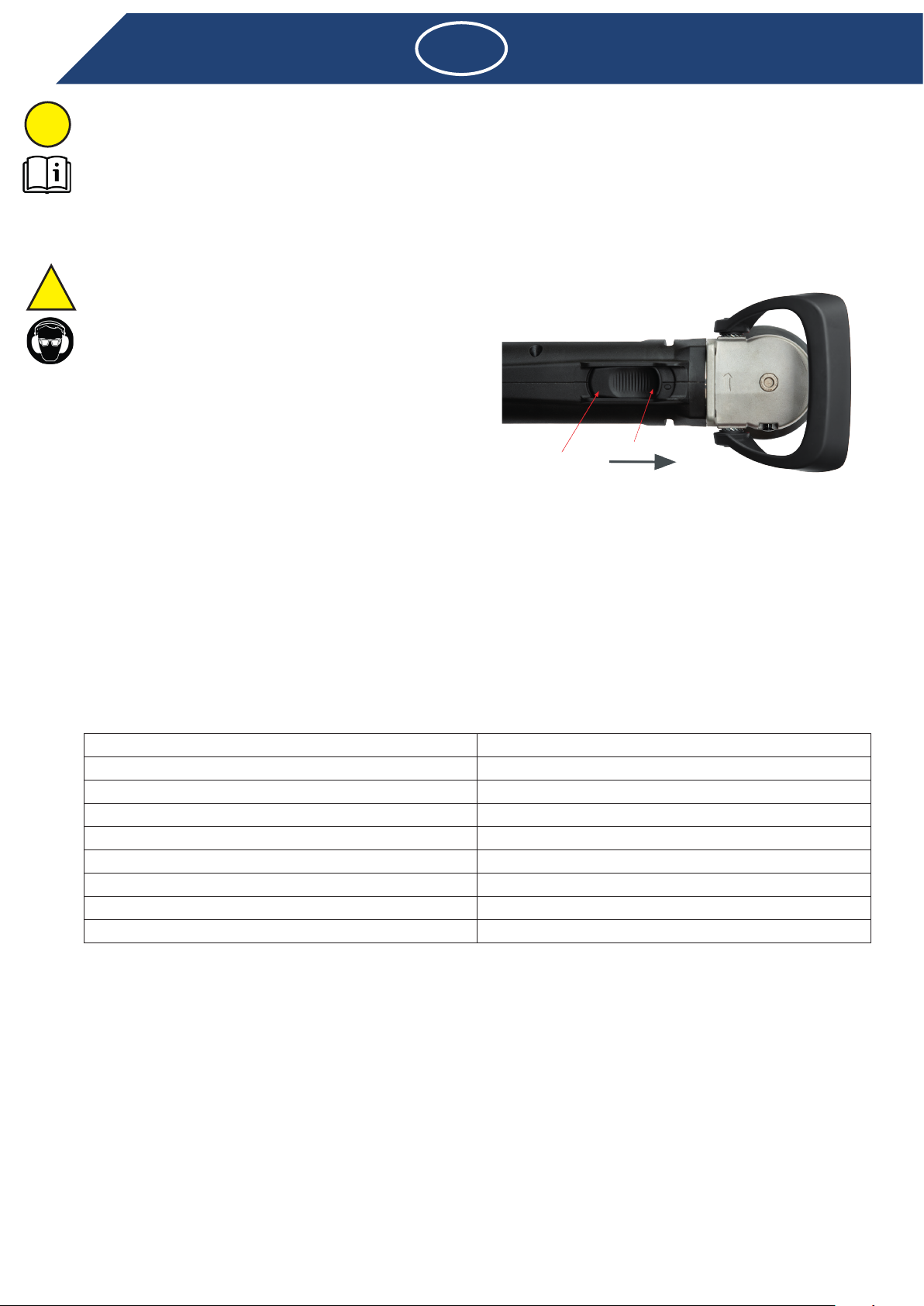
2.2.1 Turn on
and ear protection.
the machine.
to control the machine.
• Never touch the bevel head when the machine is running.
• Never use the machine above head height.
• The machine should only be used for conventional up-cut
milling.
toward
the front.
• Bring the machine slowly into contact with the work piece
only after the maximum speed has been reached.
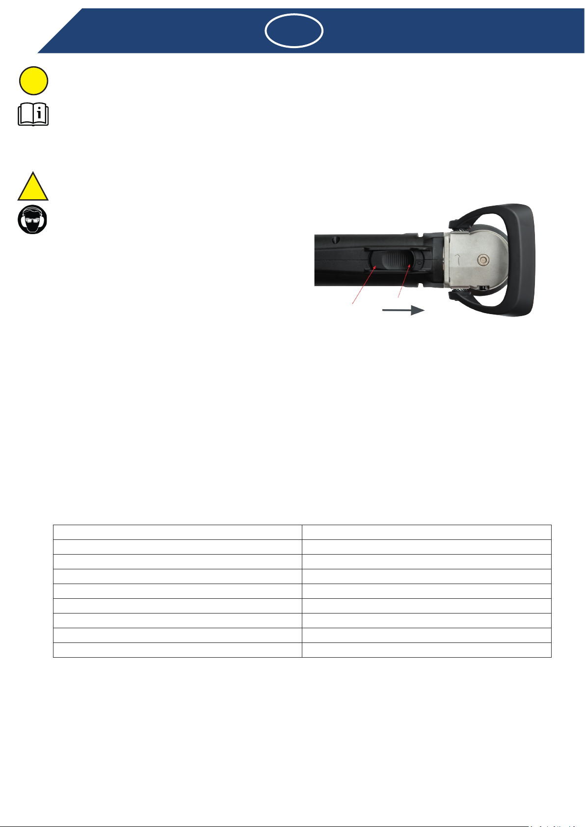
2.2.2 Turn o
• Motor stops.
2.3 Rating data
No-load speed
Max. wheel diameter 24 mm
Grinding spindle thread M6
Noise emission level
Battery capacity
Voltage
Weight w/o battery pack 2.6 kg
depending
on how the power tool is used.
estimated exposure under the actual conditions of use (these must take into account all phases of the operating
cycle, e.g. the times when the power tool is switched OFF and the times it is switched ON, but is not under load).
2.4 Operating conditions
3.1 Protective devices
!
i
EN
A
B

3.1.1 Adapt ange head
3.1.2 Protection of the machine
electronic constant speed control. When the machine is at operating temperature the temperature-dependent
overload protection reacts correspondingly earlier time.
3.2 Bevel heads
Use only bevel heads whose admissible maximum speed is equal to or higher than the no load speed of the machine.
Use only clean bevel heads!
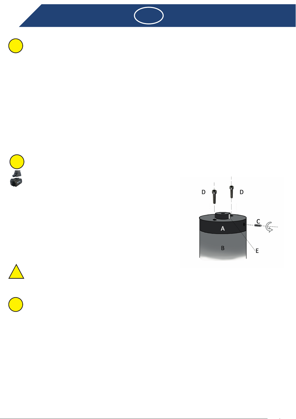
3.2.1 Placing / Changing a bevel head
• Remove the powerpack!
• Use the locking button to lock the spindle
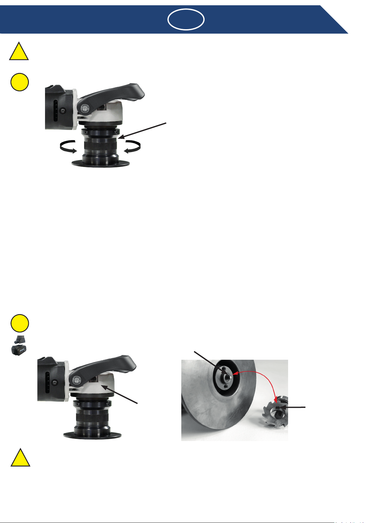
3.2.2 Fitting a bevel head
damage to the cutters!
head and can lead to a broken bevel head.
• Use the locking button to lock the spindle.
• Use the hex wrench (4 mm) to tighten the guide bearing.
Check bevel tool before use. The bevel head must be correctly mounted and must rotate freely. Perform a trial run
which vibrate!
4
EN
i
Flange head
Locking button Notch
Cylindrical pin
i
h
5
3.3 Operating instructions
• The electronic constant control maintains the speed nearly constant during idling and work under load and assures a
uniform result.
• The machine is equipped with an electronic control and integrated overload protection.
to run for a short time without load.
4.1 Preventive maintenance
frequent blowing out of the ventilation slots and protection by a fault current protection switch are advised.
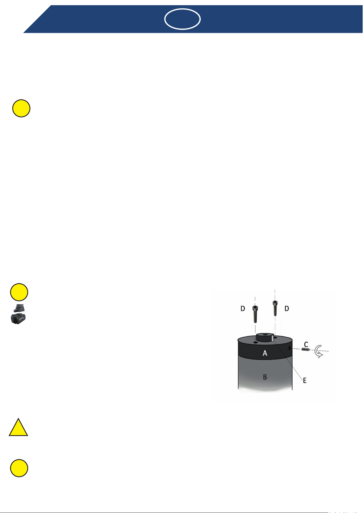
4.1.1 Changing the sacricial adapter
should also be undamaged and retain its original length. The adapter spacer and/or adapter pin may get damaged
deeper in the spacer. This removes the spacer from the spindle (B).
• Remove the damaged spacer when it has become free. Unscrew the
shoulder. Use a rubber mallet if necessary.
the spindle.
• Retighten the hex screw on the side of the spacer.
4.2 Repair
If despite strict observance of the manufacturing and testing method
connecting line must be installed by the manufacturer or its agent if safety risks are to be eliminated.
4.3 Warranty
Beveltools machines have been manufactured to quality standards and carefully inspected before shipment. The
description of the problem. If inspection shows an original defect in material or workmanship Beveltools will repair or
replace the tool without charge during the warranty period.
for purposes for which it is not intended and/or if the service and maintenance instructions not being observed by
Beveltools reserves the right to make changes or improvements to its products. Beveltools is not obligated to make
any corresponding changes or improvements in products previously manufactured or sold.
i
!
i
EN
i
h

4.4 Storage
4.5 Disposal / environmental compatibility
machine must be disposed of in an environmentally compatible recycling process.
6
EN

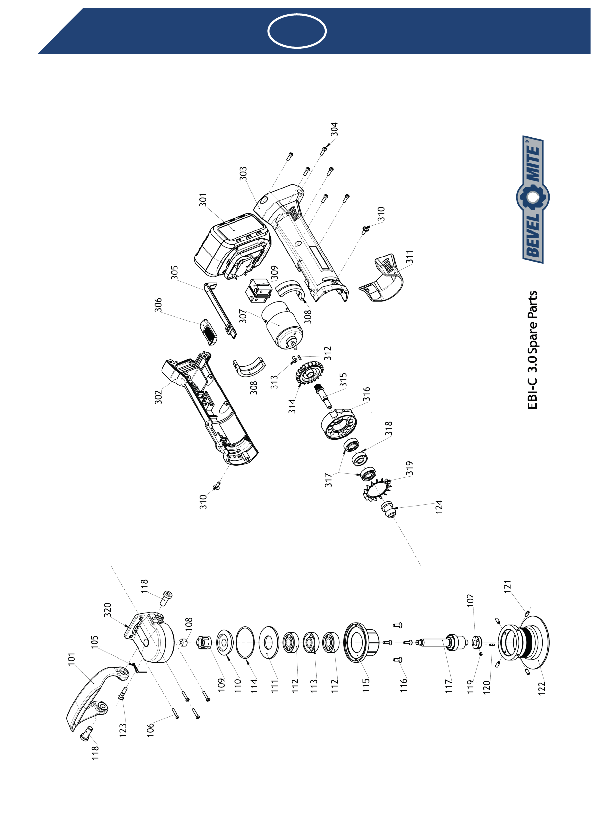
4.6 Spare parts
EN

EN
4.6.1 Spare parts list
No.Descripon Product code No. Descripon Product code
101 EBI 3.0 Handle 9150101 301 baery pack EBI-C-3.0 9152301
102 EBI 3.0 Sacricial Spacer 9150102 302 housing, right half 9152302
105 Lock Buon Spring 9150105 303 housing, le half 9152303
106 Angle Head Screw 9150106 304 motor housing screw 9152304
108 Needle Bearing 9150108 305 switch push rod 9152305
109 Lock Bushing 9150109 306 switch buon 9152306
110 Ring Gear 9150110 307 motor unit 9152307
111 Bearing Housing Spacer 9150111 308 motor isolaon 9152308
112 EBI 3.0 Bearing 9150112 309 switch 9152309
113 Bearing Spacer Rings Set 9150113 310 Stebility Screws 9152310
114 EBI Shim 9150114 311 Safety Cap 9152311
115 Bearing Housing 9150115 312 Motor Shear Pin 9152312
116 Bearing Housing Screw 9150116 313 Motor Screw 9152313
117 EBI 3.0 Spindle 9150117 314 EBI-C fan 9152314
118 Handle Screw 9230069 315 EBI-C Motor Spindle 9152315
119 Set Screw 9700201 316 Bearing Mount 9152316
120 Shear Pin 9122010 317 motor ball bearing 9152317
121 Ball Screw M4 9233001 318 motor bearing spacer set 9152318
122 EBI Flange Head 8232010 319 EBi -C Fan Protector 9152319
123 Lock Pin 9150123 320 EBI-C-3.0 Angle Head 9152320
124 Pinion Gear 9150124

9
Inhoudsopgave
1.4 EG-verklaring van overeenstemming
1.5 Verklaring van de symbolen
2.1 Voor het in gebruik nemen
2.2 In gebruik nemen
2.3 Technische gegevens
2.4 Gebruiksomstandigheden
3.1 Veiligheidsinrichtingen
4.1 Preventief onderhoud
4.2 Reparatie
4.3 Garantie
4.4 Opslag
4.6 Reserveonderdelen
NL

10
NL
1.1 Algemene veiligheidsinstructie
®EBI 3.0
WAARSCHUWING
1.2 Juist gebruik
1.3 Onjuist gebruik
1.4 EG-verklaring van overeenstemming (origineel)
1.5 Verklaring van de symbolen
Veiligheidsinstructie/waarschuwing
de bediener niet worden gegarandeerd.
Informatie
Gebruikershandleiding
Lees de gebruikershandleiding door voordat u het product in gebruik neemt.
Veiligheidsbril en gehoorbescherming
Draag een veiligheidsbril en gehoorbescherming.
Afvalverwerking
Milieubewuste afvalverwerking.
Spanning - Accu
!
i
h
11
2.1 Voor het in gebruik nemen
2.2.1 Inschakelen
veiligheidsbril en oorbescherming.
staat.
• Raak de frees nooit aan als het apparaat is ingeschakeld.
lichaam af.
• Werk nooit boven het hoofd met het apparaat.
voren. De motor loopt.
apparaat moet erop worden gelet dat beide handen niet in
de buurt van de bewerkingsplek komen.
toerental is bereikt.
• Beweeg het apparaat pas langs het werkstuk als het geleidelager tegen het werkstuk aan ligt.
de freeskop.
2.2.2 Uitschakelen
drukken.
• De motor stopt.
2.3 Technische gegevens
Stationair toerental
Max. werktuig Ø 24 mm
M6
Geluidsemissieniveau
Voltage
afhankelijk van de manier waarop het elektrische werktuig wordt gebruikt. Er
(hierbij moeten alle onderdelen
van de bedrijfscyclus in aanmerking worden genomen, bijvoorbeeld tijdstippen waarop het elektrische apparaat is
uitgeschakeld en tijdstippen waarop het weliswaar is ingeschakeld, maar onbelast loopt).
2.4 Gebruiksomstandigheden
NL
!
i
A
B
12
NL
3.1 Veiligheidsinrichtingen
3.1.1 Flenskop instellen
3.1.2 AAN-/UIT-schakelaar
3.1.3 Apparaatbeveiliging
loopt vervolgens met ca. 3.200 omw./min. verder en de elektronische toerenregelaar wordt gedeactiveerd.
temperatuurgevoelige overbelastingsbeveiliging dienovereenkomstig eerder.
3.2 Frezen
toerental op het apparaat.
Monteer uitsluitend schone freeskoppen!
3.2.1 Een freeskop verwijderen
• Gebruik de vergrendelknop om de spil te vergrendelen.
3.2.2 Een freeskop monteren
direct vervangen worden. Een niet goed functionerend geleidelager kan een gebroken freeskop tot gevolg hebben.
• Gebruik de vergrendelknop om de spil te vergrendelen.
Flenskop
i
Vergrendelknop Pingat
Meeneempin
!
!
i
h
• Draai het geleidelager vast met de meegeleverde inbussleutel (4 mm).
3.3 Werkwijze
materiaal worden bewogen.
• Te sterke druk vermindert de prestaties van het apparaat en verkort ook de levensduur van de frees.
4.1 Preventief onderhoud
apparaat automatisch uit.
4.1.2 Adapter vervangen
• Schroef vervolgens beide M4-bouten (D) telkens een halve
afstandsstuk van de spil (B).
gekomen. Schroef de twee M4-bouten los van het afstandsstuk dat
op de spindelschouder rust. Gebruik indien nodig een rubberen
hamer.
vast.
4.2 Reparatie
4.3 Garantie
13
NL
i
!
i
h
i

14
NL
repareren.
geautoriseerde personen kan geen aanspraak worden gemaakt op garantie.
producten.
4.4 Opslag
4.5 Afvalverwerking/belasting voor het milieu
15
4.6 Reserveonderdelen
16
NL

16
NL
4.6.1 Reserveonderdelenlijst
No.Descripon Product code No. Descripon Product code
101 EBI 3.0 Handle 9150101 301 baery pack EBI-C-3.0 9152301
102 EBI 3.0 Sacricial Spacer 9150102 302 housing, right half 9152302
105 Lock Buon Spring 9150105 303 housing, le half 9152303
106 Angle Head Screw 9150106 304 motor housing screw 9152304
108 Needle Bearing 9150108 305 switch push rod 9152305
109 Lock Bushing 9150109 306 switch buon 9152306
110 Ring Gear 9150110 307 motor unit 9152307
111 Bearing Housing Spacer 9150111 308 motor isolaon 9152308
112 EBI 3.0 Bearing 9150112 309 switch 9152309
113 Bearing Spacer Rings Set 9150113 310 Stebility Screws 9152310
114 EBI Shim 9150114 311 Safety Cap 9152311
115 Bearing Housing 9150115 312 Motor Shear Pin 9152312
116 Bearing Housing Screw 9150116 313 Motor Screw 9152313
117 EBI 3.0 Spindle 9150117 314 EBI-C fan 9152314
118 Handle Screw 9230069 315 EBI-C Motor Spindle 9152315
119 Set Screw 9700201 316 Bearing Mount 9152316
120 Shear Pin 9122010 317 motor ball bearing 9152317
121 Ball Screw M4 9233001 318 motor bearing spacer set 9152318
122 EBI Flange Head 8232010 319 EBi -C Fan Protector 9152319
123 Lock Pin 9150123 320 EBI-C-3.0 Angle Head 9152320
124 Pinion Gear 9150124

Inhaltsverzeichnis
1.2 Bestimmungsgemässe Verwendung
1.3 Nicht bestimmungsgemässe Verwendung
1.5 Symbolerklärung
2.1 Vor der Inbetriebnahme
2.2 Inbetriebnahme
2.3 Leistungsdaten
2.4 Betriebsbedingungen
3.2 Fräsköpfe
4.1 Vorbeugende Instandhaltung
4.2 Reparatur
4.3 Garantieleistung
4.4 Lagerung
4.5 Entsorgung / Umweltverträglichkeit
DE

DE
1.1 Allgemeine sicherheitstechnischer Hinweise
Diese Betriebsanleitung gilt für die Maschinen Bevel Mite®EBI 3.0
WARNUNG
1.2 Bestimmungsgemässe Verwendung
1.3 Nicht bestimmungsgemässe Verwendung
1.4 EG-Konformitätserklärung (Original)
1.5 Symbolerklärung
Sicherheitshinweis / Warnung
nicht gewährleistet.
Information
Leistungsfähigkeit des Produktes ausschöpfen.
Betriebsanleitung
Vor Inbetriebnahme des Produktes Betriebsanleitung lesen.
Schutzbrille und Gehörschutz
Entsorgung
Umweltfreundliche Entsorgung.
Spannung - Akku
!
i
h

2.1 Vor der Inbetriebnahme
• Regelmäßig Fräskopf auf Verschleiß prüfen.
• Scharfe Fräsköpfen bringen gute Schnittleistungen und schonen das Gerät.
2.2.1 Einschalten
Stand sorgen.
Bearbeitungsstelle entfernt sind.
beachten.
2.2.2 Ausschalten
• Motor schaltet ab.
2.3 Leistungsdaten
24 mm
Schleifspindelgewinde M6
Schallleistungspegel
Stromspannung
Gewicht ohne Batterie
-
abhängig
von der Art und Weise, in der das Elektrowerkzeug verwendet wird.
-
gungen beruhen (hierbei sind alle Anteile des Betriebszyklus zu berücksichtigen, beispielsweise Zeiten, in denen das
Elektrowerkzeug abgeschaltet ist, und solche, in denen es zwar eingeschaltet ist, aber ohne Belastung läuft).
2.4 Betriebsbedingungen
3.1 Schutzvorrichtungen
19
!
i
A
B
DE
!
This manual suits for next models
1
Table of contents
Languages:
Other Beveltools Power Tools manuals

Beveltools
Beveltools Mate EBA-12 User manual

Beveltools
Beveltools Bevel Mite ABIS-06 User manual

Beveltools
Beveltools Bevel Mate ABA-12 User manual

Beveltools
Beveltools Bevel Mate EBA 3.0 User manual

Beveltools
Beveltools Mite EBI-06 Premium Instruction manual

Beveltools
Beveltools Bevel Mate EBA-12 S Instruction manual

Beveltools
Beveltools Bevel Mite EBI-06 Premium Instruction manual

Beveltools
Beveltools Bevel Mate EBA-12 S User manual

Beveltools
Beveltools Bevel Mite ABIS-06 Premium User manual


