Beveltools Bevel Mate EBA 3.0 User manual

EN
NL
DE
FR
ES
Instruction manual
Gebruikershandleiding
Betriebsanleitung
Mode d’emploi
Instrucciones de funcionamiento
www.beveltools.com
Bevel Mate® EBA 3.0

1
Content
1.1 General notes on safety
1.2 Use of the machine for purposes for which it is intended
1.3 Incorrect use
1.4 CE declaration of conformity
1.5 Symbol legend
2.1 Prior to taking the machine into service
2.2 Taking the machine into service
2.3 Rating data
2.4 Operating conditions
3.1 Protection devices
3.2 Bevel heads
3.3 Operating instructions
4.1 Preventive maintenance
4.2 Repair
4.3 Warranty
4.4 Storage
4.5 Disposal / Environmental compatibility
4.6 Spare parts
EN

2
EN
1.1 General notes on safety
This operation manual is applicable for the machine Bevel Mate® EBA 3.0.
The machines may only be handled by personnel who is qualifi ed. Always wear protective clothing, safety shoes,
safety glasses and ear protection.
WARNING Read all safety warnings and all instructions. Failure to follow the warnings and instructions may result in
electric shock, fi re and/or serious injury. Save all warnings and instructions for future reference.
1.2 Use of the machine for purposes for which it is intended
The machines are intended for the purpose of milling metal and plastic materials without the use of water. The
machines are electric, handheld machines for machining steel, aluminum, aluminum alloys, brass and plastic for
commercial use in industrial applications, for manual weld preperations and for making visible edges in installation-
and machine building.
1.3 Incorrect use
All uses other than those described under section 1.2 are regarded as incorrect use and are therefore not admissible.
1.4 CE declaration of conformity
Beveltools BV of P.O.box 190, 6880 AD Velp Gld, hereby declares under sole responsibility that the product with the
serial or batch no. (see reverse side) complies with the requirements under the Directive 2004/108/EC, 2006/42/EC,
2011/65/EU. Applied standards: EN ISO 12100, EN 60745, EN 55014-1, EN 55014-2, EN 61000-3-2, EN 61000-3-3.
Document Agent: J.E. Hofman, July 2014 J.E. Hofman, Managing Director.
1.5 Symbol legend
Note on safety / Warning
This information serves to achieve safe operation. Failure to observe this information may compromise the operator‘s
safety.
Information
This information serves for a good understanding of the operation of the product, thereby permitting full exploitation
of the operational potential of the product.
Technical Document
Read the technical document prior to commissioning.
Safety glasses and ear protection
Wear safety glasses and ear protection.
Disposal
Friendly-to-the-environment disposal.
Power connector
Before any work is carried out on the machine, disconnect the power connector.
!
i

3
2.1 Prior to taking the machine into service
Before connecting the tool to a power source, be sure the voltage supplied is the same as specifi ed on the name plate
of the tool. The power supply should not vary more than 10% above or below the voltage indicated on the name plate.
Working with worn or damaged bevel heads will cause the machine to fail.
• Check bevel head prior to use.
• A sharp bevel head will increase cutting speed and machine life.
• The bevel head must be changed regularly.
• The bevel head must be mounted centrally and positioned against the limit stop.
• The maximum allowable speed of the tool and of the chuck may not be exceeded under any circumstances.
• Observe national regulations.
2.2 Taking the machine into service
Preselect speed with adjusting wheel according to speed table.
Adjusting wheel increment Min-1 / rpm
1 4.200
2 5.200
3 6.400
4 7.600
5 8.800
6 10.000
During operation, never increase the speed of the machine to above that of the maximum admissible speed of the
grinding tool!
2.2.1 Turn on
• Always wear protective clothing, safety shoes, safety glasses and ear protection.
• Make sure you always have a fi rm footing when working with the machine.
• Whatever the position of the machine, always use two hands to control the machine.
• Never touch the bevel head when the machine is running.
• Never use the machine above head height.
• The machine should only be used for conventional up-cut milling.
• To turn the machine on, press the ON/OFF handle and hold.
• Bring the machine slowly into contact with the work piece only after the selected tool speed has been reached.
• When cutting a bevel, always move the machine from left to right against the rotation direction of the bevel head.
• When machining bore holes, always work in a clockwise direction.
2.2.2 Turn off
• Take beveling machine from work piece and turn off .
• Motor stops.
2.3 Rating data
Power voltage (cf. replacement parts list) 120/230V; 50/60 Hz; 120/230V
Power Input 1530 W
Power Output 1000 W
No-load speed 10500 min-1/rpm
Max. wheel diameter 45 mm
Grinding spindle thread M8
Sound pressure level according to EN 60745 89 dB (A) K = 3 dB
Noise emission level 100 dB (A) K = 3 dB
Vibration according to EN 60745 <2.5 m/s2 K = 1.5m/s2
Weight w/o cord set 4.3 kg
Protection class / II
!
i
EN

4
EN
The specifi ed vibration value was measured with a standardized test procedure. It can be used to compare products or
to make an initial assessment of the exposure. The vibration emissions may diff er from the specifi ed value, depending
on how the power tool is used. Operating personnel must be protected with defi ned safety measures based on the
estimated exposure under the actual conditions of use (these must take into account all phases of the operating
cycle, e.g. the times when the power tool is switched OFF and the times it is switched ON, but is not under load).
2.4 Operating conditions
Temperature range during operation: 0 to +50°C
Relative air humidity: 95% at +10°C not condensed
3.1 Protective devices
The machine may only be operated with the fl ange head and the additional handle fi tted!
3.1.1 Flange head
Adapt fl ange head
• Turn the fl ange head until it has reached the right depth.
• Rotate the guide plate until the required bevel height has been set as shown by the fi xed main scale.
Cleaning depth mechanism
• Remove guide bearing and bevel head.
• Turn the fl ange head until it comes off .
• Clean all parts and replace defective parts.
• Lubricate the thread with Tefl on spray and gears with a little multi-purpose grease.
• Re-assemble in reverse order.
3.1.2 Additional handle
The additional handle must be screwed in at the left and right with the supplied screws.
3.1.3 ON/OFF switch
Two-pole ON/OFF switch with turn-on inhibit and locking.
3.1.4 Protection of the machine
• Starting current limitation. The electronically controlled soft starting provides for smooth starting of the machine.
Due to the low machine starting current a 16A fuse is adequate.
• Temperature-dependent overload protection. For protection against overheating, when a critical temperature is
reached, the electronic safety feature switches into the cool down mode. Then the machine continues to run at
approx.: 3.200 rpm and the electronic constant speed control is deactivated. After a cool-down time of approx.
10 - 20 sec. the machine is again ready for operation. Turn the machine off and back on again to activate the
electronic constant speed control. When the machine is at operating temperature the temperature-dependent
overload protection reacts correspondingly earlier time.
• Overvoltage/restarting protection. On short-time outage of the power voltage (pulled power connector, unstable
power voltage etc.) the machine will stop. On recovery of the power voltage the machine has to be turned off and
back on again. The machine is then ready for operation.
i

5
3.2 Bevel heads
Use only bevel heads whose admissible maximum speed is equal to or higher than the no load speed of the machine.
Use only clean tools!
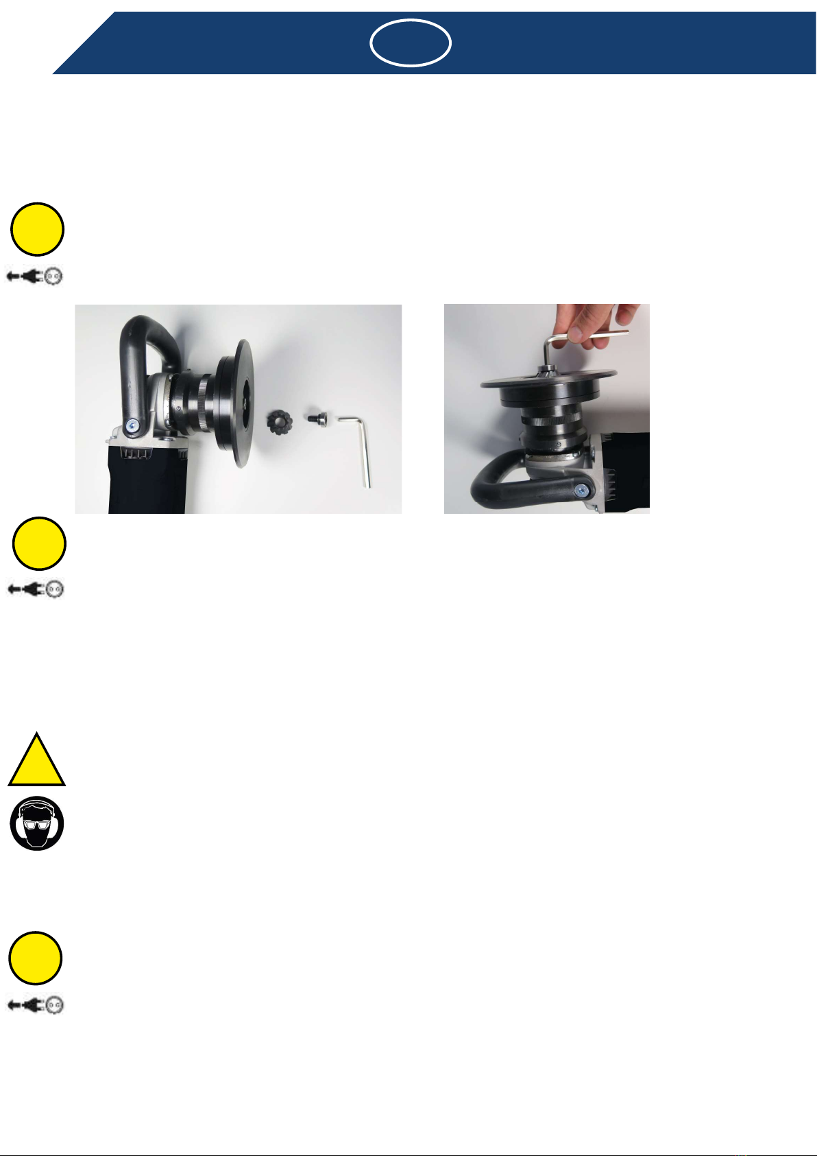
3.2.1 Changing a bevel head
• Disconnect from power supply.
• Turn the fl ange head to its maximum depth.
• Lock spindle by pressing the orange locking button on the back of the gearbox.
• Use the hex wrench (5 mm) to unscrew the guide bearing.
• Take the bevel head off .
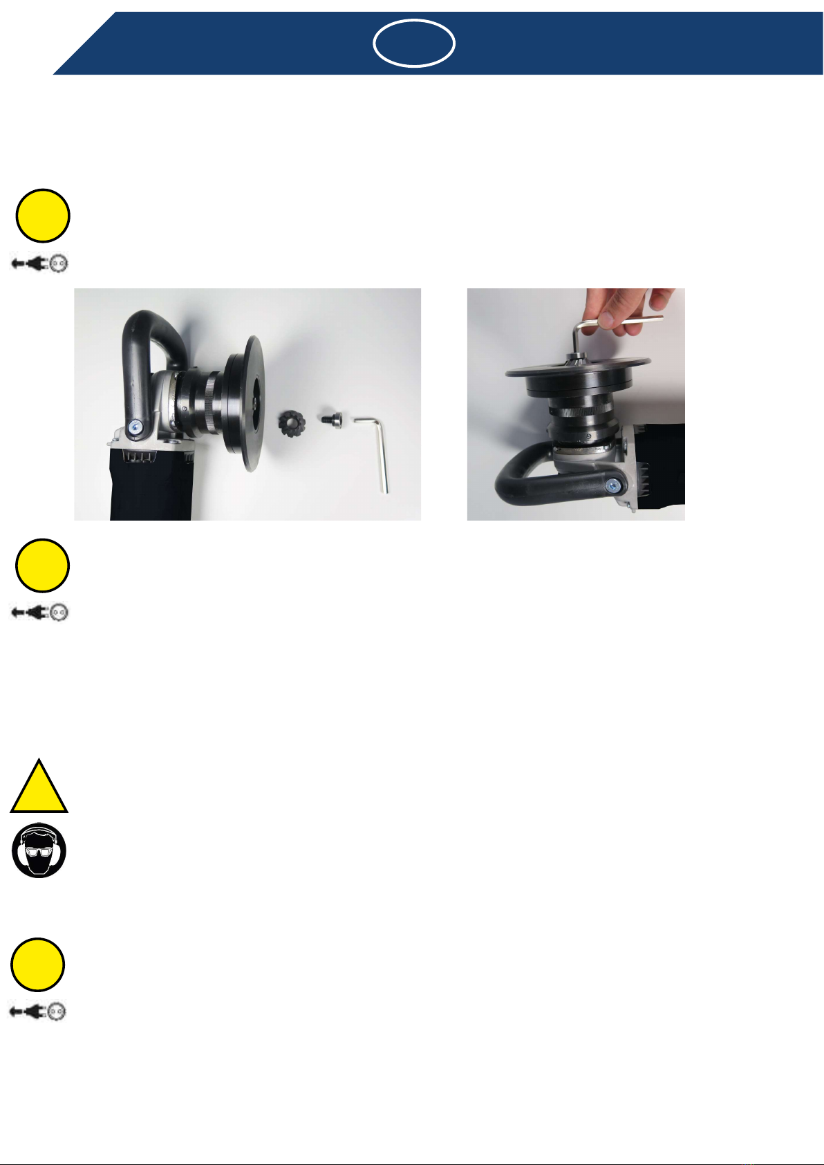
3.2.2 Mounting a bevel head
• Before mounting the bevel head, clean the surface of the adapter and bevel head.
• Check the guide bearing, it should run smoothly, a guide bearing that doesn’t run smoothly will damage the bevel
head and can lead to a broken bevel head.
• Place bevel head on the adapter, the pin on the adapter should accurately fi t into the pinhole of the bevel head.
• Lock spindle by pressing the orange locking button on the back of the gearbox. Use the hex wrench (5 mm) to
tighten the guide bearing as tight as possible.
• Check if the bevel head runs smoothly and true, not true running bevel heads must be replaced immediately.
Check bevel tool before use. The bevel head must be correctly mounted and must rotate freely. Perform a trial run
over a period of min. 30 seconds without load. Do not use bevel heads which are damaged, which do not run true or
which vibrate!
3.3 Operating instructions
• To achieve an optimum bevel result, move beveling tool uniformly with light pressure.
• The electronic constant control maintains the speed nearly constant during idling and work under load and assures a
uniform result.
• Excessive pressure lessens the working capability of the machine, as well as the life of the bevel head.
• The machine is equipped with an electronic control and integrated overload protection.
• If the machine is overloaded, the speed will drop drastically. Immediately take the load off the machine and allow
to run for a short time without load.
• Maximum depth per cut, on steel, no more than 4 mm with a maximum power-on time of 50%.
4.1 Preventive maintenance
• To work eff ectively and safely, keep the machine and the ventilation slots clean at all times.
• Keep the thread and grooves on the bearing housing and the internal thread of the fl ange head clean to prevent
jamming and premature failure of the ball screws.
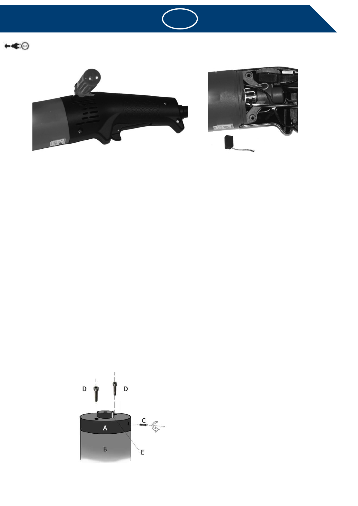
• After approx. 200 operating hours check carbon brushes and replace if necessary. Clean motor housing and replenish
grease fi lling in gearbox housing. When the brushes are spent, the machine will stop automatically.
• To maintain the protective insulation the machine must be subjected to a technical safety inspection. This work
must be done exclusively by a specialized electrical workshop.
• When working on metal under extreme working conditions, conductive dust deposits can occur inside the machine,
thereby impairing the protective insulation of the machine. In such cases the use of a stationary vacuuming system,
frequent blowing out of the ventilation slots and protection by a fault current protection switch are advised.
i
!
i
i
EN

6
EN
4.1.1 Changing the carbon brushes
The Automatic-Stop feature protects the machine from defects due to excessively consumed carbon brushes. The
machine is equipped with two carbon brushes, i.e. one is installed in each handle half.
The carbon brushes must be changed as follows:
• Unscrew four screws and remove the handle halves.
• Lift spring with screwdriver and remove brush.
• Install new brushes.
• Clean carbon brush holders, making absolutely sure not to change the arrangement of the elements of the carbon
brush assembly.
• Fit handle halves and fasten with four screws.
• Repeat this on the opposite side, making absolutely sure to avoid both handle halves from being opened at the same
time.
4.1.2 Replacing the Adapter Spacer
In order to ensure correct operation and extend the service life of the bevel heads, it is essential to ensure that the
surface of the adapter spacer is unblemished, i.e. without pits, deep scratches and\or broken edges. The adapter pin
should also be undamaged and retain its original length. The adapter spacer and/or adapter pin may get damaged
under certain conditions, however both can easily be replaced.
Replacing the spacer:
• Turn the fl ange head until it comes off .
• Unscrew the hex screw (C) on the side of the spacer (A).
• Screw the two M5 bolts (D) in the holes in the top of the spacer until they just touch the spindle shoulder (B).
Continue to screw the two M5 bolts alternately in small increments until the spacer is forced off the spindle.
• Now continue to screw the two bolts alternately in half turns deeper into the spacer. Remove the damaged spacer
when it comes off the spindle. Unscrew the two M5 bolts from the spacer and keep these for later use.
• Install the new spacer, ensuring that it rests securely on the spindle shoulder. Use a rubber mallet if necessary.
• Replace the adapter pin (E), ensuring the top is level with the top of the spindle.
• Retighten the hex screw on the side of the spacer.

4.2 Repair
If despite strict observance of the manufacturing and testing method the tool should happen to fail, it must
be repaired by an authorized agency. Any replacement needed for the connecting line must be installed by the
manufacturer or its agent if safety risks are to be eliminated.
4.3 Warranty
Beveltools machines have been manufactured to quality standards and carefully inspected before shipment. The
warranty period for all Beveltools machines is 12 months from the original date of purchase. If repair is required,
the user must return the complete tool to the manufacturer or nearest authorized dealer. Complaints can only be
honoured if the machine is returned in the undissembled condition, with copy of the purchase invoice and clear
description of the problem. If inspection shows an original defect in material or workmanship Beveltools will repair or
replace the tool without charge during the warranty period.
The warranty does not apply to normal use or wear and tear. In the event of the tool being improperly handled, used
for purposes for which it is not intended and/or if the service and maintenance instructions not being observed by
authorized persons, no warranty shall be in eff ect for damages/consequential damages.
Beveltools reserves the right to make changes or improvements to its products. Beveltools is not obligated to make
any corresponding changes or improvements in products previously manufactured or sold.
4.4 Storage
Temperature range during operation -15°C up to +50°C
Max. relative air humidity 90 % at + 30°C
65 % at + 50°C
4.5 Disposal / environmental compatibility
This machine consists of materials which can be disposed of in a recycling process. Before disposal, render the
machine unusable. Do not throw the machine into the garbage collection. According to national regulations this
machine must be disposed of in an environmentally compatible recycling process.
EN
i
7

EN
Notes:
8

9
4.6 Spare parts
EN
A drawing of spare parts will soon be available.
Please check for the latest version of this manual
on our website
www.beveltools.com/downloads

10
EN
4.6.1 Spare parts list
A list of spare parts will soon be available. Please
check for the latest version of this manual on our
website
www.beveltools.com/downloads

11
Inhoudsopgave
1.1 Algemene veiligheidsinstructie
1.2 Juist gebruik
1.3 Onjuist gebruik
1.4 EG-verklaring van overeenstemming
1.5 Verklaring van de symbolen
2.1 Voor het in gebruik nemen
2.2 In gebruik nemen
2.3 Technische gegevens
2.4 Gebruiksomstandigheden
3.1 Veiligheidsinrichtingen
3.2 Frezen
3.3 Werkwijze
4.1 Preventief onderhoud
4.2 Reparatie
4.3 Garantie
4.4 Opslag
4.5 Afvalverwerking/belasting voor het milieu
4.6 Reserveonderdelen
NL

12
NL
1.1 Algemene veiligheidsinstructie
Deze gebruikshandleiding geldt voor het apparaat Bevel Mate® EBA 3.0.
Uitsluitend gekwalifi ceerd personeel mag het apparaat gebruiken. Draag altijd beschermende kleding,
veiligheidsschoenen, veiligheidsbril en oorbescherming.
WAARSCHUWING Lees alle veiligheidsinstructies en aanwijzingen. Als veiligheidsinstructies en aanwijzingen niet
worden opgevolgd, kan dit een elektrische schok, brand en/of zwaar letsel tot gevolg hebben.
Bewaar alle veiligheidsinstructies en aanwijzingen voor toekomstig gebruik.
1.2 Juist gebruik
De apparaten zijn bedoeld voor het frezen van metalen en kunststof materiaal, zonder het gebruik van water. De
apparaten zijn elektrisch werkende handapparaten voor het bewerken van werkstukken van staal, aluminium,
aluminiumlegeringen, messing en kunststof voor commercieel gebruik in industriële toepassingen, bij het handmatig
voorbewerken van lasnaden en voor het aanbrengen van zichtranden in de installatie-, apparaat- en machinebouw.
1.3 Onjuist gebruik
Alle andere dan onder 1.2 beschreven toepassingen gelden als onjuist gebruik en zijn daarom niet toegestaan.
1.4 EG-verklaring van overeenstemming (origineel)
Beveltools BV, postbus 190, 6880 AD Velp (Gld) verklaart hiermee in eigen verantwoordelijkheid dat het product met
serie- of chargenr. (zie achterzijde) voldoet aan de eisen zoals deze worden gesteld in de richtlijnen 2004/108/EG,
2006/42/EG, 2011/65/EU. Toegepaste normen: EN ISO 12100, EN 60745, EN 55014-1, EN 55014-2, EN 61000-3-2, EN
61000-3-3. Gevolmachtigde persoon voor de documentatie: J.E. Hofman, juli 2014 J.E. Hofman, Directeur.
1.5 Verklaring van de symbolen
Veiligheidsinstructie/waarschuwing
Deze informatie dient voor een veilige werking. Als deze informatie niet in acht wordt genomen, kan de veiligheid van
de bediener niet worden gegarandeerd.
Informatie
Deze informatie dient om de werking van het product te begrijpen. Hierdoor kan het product optimaal worden benut.
Gebruikershandleiding
Lees de gebruikershandleiding door voordat u het product in gebruik neemt.
Veiligheidsbril en gehoorbescherming
Draag een veiligheidsbril en gehoorbescherming.
Afvalverwerking
Milieubewuste afvalverwerking.
Netstekker
Trek voor alle werkzaamheden aan het apparaat de stekker uit het stopcontact.
!
i

13
2.1 Voor het in gebruik nemen
Controleer de netspanning. De spanning van de stroombron moet overeenkomen met de gegevens op het typeplaatje.
Controleer de frezen: stompe frezen kunnen materiële schade en overbelasting van het apparaat tot gevolg hebben!
• Controleer de freeskop regelmatig op slijtage.
• Een scherpe freeskop zorgt voor een optimaal snijvermogen, waardoor het apparaat minder zwaar wordt belast.
• Vervang de freeskop op tijd.
• Het freeswerktuig moet centrisch en tot de aanslag worden vastgeklemd.
• Het maximaal toegestane toerental van het werktuig en de spaninrichting mag in geen geval worden overschreden.
• Neem de landspecifi eke voorschriften in acht.
2.2 In gebruik nemen
Stel het toerental conform de toerentaltabel in met het stelwieltje.
Stand van het stelwieltje omw./min.
1 4.200
2 5.200
3 6.400
4 7.600
5 8.800
6 10.000
Tijdens de werking mag het op het freeswerktuig afgestemde toerental nooit worden verhoogd!
2.2.1 Inschakelen
• Draag altijd beschermende kleding, veiligheidsschoenen, veiligheidsbril en oorbescherming.
• Zorg dat u bij werkzaamheden met het apparaat stevig staat.
• Raak de frees nooit aan als het apparaat is ingeschakeld.
• Beweeg het apparaat tijdens de werking altijd van het lichaam af.
• Werk nooit boven het hoofd met het apparaat.
• Druk de AAN-/UIT-schakelaar op de handgreep in en houd deze ingedrukt. De motor loopt.
• Tweehandige bediening: het apparaat kan uitsluitend met twee handen worden bediend. Bij het werken met het
apparaat moet erop worden gelet dat beide handen niet in de buurt van de bewerkingsplek komen.
• Zet het apparaat pas op het werkstuk als het ingestelde toerental is bereikt.
• Beweeg het apparaat pas langs het werkstuk als het geleidelager tegen het werkstuk aan ligt.
• Bij het afkanten moet het freesapparaat altijd van links naar rechts worden bewogen. Let op de draairichting van
de freeskop.
• Bij de bewerking van de binnenkant van gaten/buizen, frezen met de klok mee.
2.2.2 Uitschakelen
• Neem het freesapparaat van het materiaal en schakel uit.
• De motor stopt.
2.3 Technische gegevens
Netspanning (zie onderdelenlijst) 120/230V; 50/60 Hz; 120/230V
Opgenomen vermogen 1530 W
Afgegeven vermogen 1000 W
Stationair toerental 10500 omw./min.
Max. werktuig Ø 45 mm
Slijpspilschroef M8
Geluidsdrukniveau EN 60745 89 dB (A) K = 3 dB
Geluidsemissieniveau 100 dB (A) K = 3 dB
Trillingen EN 60745 <2,5 m/s2 K = 1,5m/s2
Gewicht zonder kabel 4,3 kg
Beschermingsklasse / II
!
i
NL

14
NL
De aangegeven trillingswaarde werd na een test gemeten. Deze kan worden gebruikt om producten te vergelijken
of voor een inschatting van de blootstelling. De trillingswaarde kan tijdens het daadwerkelijke gebruik afwijken
van de aangegeven waarde, afhankelijk van de manier waarop het elektrische werktuig wordt gebruikt. Er
moeten veiligheidsmaatregelen ter bescherming van de bediener worden vastgelegd, die gebaseerd zijn op een
inschatting van de blootstelling tijdens daadwerkelijke gebruiksomstandigheden (hierbij moeten alle onderdelen
van de bedrijfscyclus in aanmerking worden genomen, bijvoorbeeld tijdstippen waarop het elektrische apparaat is
uitgeschakeld en tijdstippen waarop het weliswaar is ingeschakeld, maar onbelast loopt).
2.4 Gebruiksomstandigheden
Temperatuurbereik werking: 0 tot +50°C
Relatieve luchtvochtigheid: 95% bij +10°C niet gecondenseerd
3.1 Veiligheidsinrichtingen
Het apparaat mag uitsluitend in combinatie met de fl enskop en de extra handgreep worden gebruikt!
3.1.1 Flenskop
Flenskop instellen
• Draai de fl enskop op de gewenste werkdiepte.
• Draai de ring, tot u op de schaalverdeling de gewenste waarde voor de freesdiepte kunt afl ezen.
Diepteinstellingsmechanisme reinigen
• Verwijder het lager en de frees.
• Draai de fl enskop helemaal los.
• Reinig alle onderdelen grondig. Vervang defecte onderdelen.
• Smeer de kogelgeleidingen op de haakse overbrenging met vrij verkrijgbaar multipurpose-vet.
• Monteer alle onderdelen weer in omgekeerde volgorde.
3.1.2 Extra handgreep
De extra handgreep moet links en rechts worden vastgeschroefd met de meegeleverde schroeven.
3.1.3 AAN-/UIT-schakelaar
Tweepolige AAN-/UIT-schakelaar met inschakelblokkering en vergrendeling.
3.1.4 Apparaatbeveiliging
• Startstroombegrenzing. De elektronisch geregelde softstart zorgt dat het apparaat geleidelijker start. Door de
geringe startstroom van het apparaat is een 16A-zekering voldoende.
• Temperatuurafhankelijke overbelastingsbeveiliging. Ter bescherming tegen oververhitting schakelt de
veiligheidselektronica in de afkoelmodus zodra een bepaalde kritieke temperatuur is bereikt. Het apparaat
loopt vervolgens met ca. 3.200 omw./min. verder en de elektronische toerenregelaar wordt gedeactiveerd.
Na een afkoeltijd van ca. 10-20 sec. kan het apparaat weer worden gebruikt. Schakel het apparaat uit en weer
in om de elektronische toerenregelaar te activeren. Bij een apparaat dat al op bedrijfstemperatuur is, reageert de
temperatuurgevoelige overbelastingsbeveiliging dienovereenkomstig eerder.
• Onderspanningsbeveiliging/herstartbeveiliging. Door kortstondige stroomuitval (stekker eruit, elektriciteitsnet
niet stabiel etc.) stopt het apparaat. Als de stroomtoevoer weer is hersteld, moet het apparaat worden uit- en
ingeschakeld. Het apparaat is bedrijfsklaar.
i

15
3.2 Frezen
Gebruik uitsluitend freeskoppen waarvan het maximaal toelaatbare toerental gelijk aan of hoger is dan het onbelaste
toerental op het apparaat.
Monteer uitsluitend schone freeskoppen!
3.2.1 Een freeskop verwijderen
• Schakel het apparaat uit met de AAN-/UIT-schakelaar. Trek de stekker uit het stopcontact.
• Draai de geleidingsringeenheid (geleidingsring + bevestiging) helemaal terug.
• Vergrendel de aandrijfas met de oranje vergrendelknop aan de achterzijde van de machine.
• Draai het geleidelager in het midden los met de bijgeleverde inbussleutel.
• Verwijder de frees.
3.2.2 Een freeskop monteren
• Reinig het geleidelager en de spanfl ens. Controleer of het geleidelager vrij loopt. Als dat niet het geval is, moet het
direct vervangen worden. Een niet goed functionerend geleidelager kan een gebroken freeskop tot gevolg hebben.
• Plaats de freeskop op de spindel, de freeskop dient exact op de centreerpin van de spindel te worden geplaatst. Die
dient op zijn beurt exact in de boring van de freeskop te grijpen.
• Vergrendel de aandrijfas met de oranje vergrendelknop aan de achterzijde van de machine. Draai het geleidelager
zo strak als mogelijk vast met de meegeleverde inbussleutel.
• De freeskop moet probleemloos rondlopen. Gebruik geen freeskoppen die niet exact rond zijn!
Laat het apparaat proefdraaien! Controleer freeskoppen voor gebruik. De freeskop moet zonder problemen zijn
gemonteerd en vrij rond kunnen draaien. Laat het apparaat minimaal 30 seconden onbelast proefdraaien. Gebruik
geen beschadigde of trillende freeskoppen of freeskoppen die niet volkomen rond zijn!
3.3 Werkwijze
• Voor een optimaal freesresultaat moet de freeskop onder lichte druk gelijkmatig over de rand van het te bewerken
materiaal worden bewogen.
• De elektronische toerenregelaar houdt het onbelast en belast toerental nagenoeg gelijk en garandeert zo een
gelijkmatig werkvermogen.
• Te sterke druk vermindert de prestaties van het apparaat en verkort ook de levensduur van de frees.
• Het apparaat is uitgerust met elektronica en een geïntegreerde overbelastingsbeveiliging.
• Als het apparaat wordt overbelast, neemt het toerental sterk af. Oefen dan geen druk meer uit en laat het apparaat
korte tijd onbelast lopen.
• De maximale freesdiepte per run mag op staal niet meer dan 4 mm zijn, bij een maximale gebruiksduur van 50%.
4.1 Preventief onderhoud
• Houd de ventilatieopeningen altijd schoon om goed en veilig te werken.
• Houd het schroefdraad en de groeven op het lagerhuis en de binnenschroefdraad van de fl enskop goed schoon om
blokkering en vroegtijdig uitval van de kogelschroeven te voorkomen.
• Na een bedrijfsduur van ca. 200 uur moeten de koolborstels worden gecontroleerd en eventueel vervangen. Reinig
de behuizing van de motor en ververs het vet in het versnellingsbak. Als de koolborstels versleten zijn, gaat het
apparaat automatisch uit.
• Om te garanderen dat de randaarde van het apparaat goed functioneert, moet deze aan een veiligheidstechnische
controle worden onderworpen. Deze werkzaamheden mogen uitsluitend door een elektricien worden uitgevoerd.
i
i
!
i
NL

16
NL
• Onder extreme gebruiksomstandigheden kunnen bij de bewerking van metalen geleidende stofdeeltjes binnenin
het apparaat komen. Hierdoor kan de randaarde van het apparaat worden beïnvloed. In dergelijke gevallen is het
raadzaam om gebruik te maken van een stationaire afzuiginstallatie, om de ventilatieopeningen regelmatig schoon
te blazen en om een aardlekschakelaar (FI) voor te schakelen.
4.1.1 Koolborstels vervangen
De automatic-stop beschermt het apparaat tegen een defect door te sterk afgesleten koolborstels. Het apparaat is
uitgerust met twee koolborstels, d.w.z. er bevindt zich één in iedere greephelft.
Het vervangen van de koolborstels gaat als volgt in zijn werk:
• Draai de schroeven los en verwijder de handgreephelften.
• Til met een schroevendraaier de veer op en verwijder de grafi etblokjes.
• Reinig de koolborstelhouder.
• Plaats nieuwe grafi etblokjes. Let daarbij te allen tijde op de plaatsing van de koolborstels.
• Plaats de greephelften en bevestig ze weer met de vier schroeven.
• Herhaal dit voor de tegenoverliggende zijde. Voorkom daarbij dat beide greephelften tegelijkertijd geopend zijn.
4.1.2. Adapter Spacer vervangen
Voor een goede werking en langere levensduur van de frezen is het essentieel dat het oppervlak van de freesopname
zuiver is. Dus zonder putjes, diepe krassen en/of afgebroken randen. Ook het meeneempinnetje dient zijn originele
vorm en hoogte te hebben. Door bijzondere gebruiksomstandigheden kan de freesopname (adapter spacer) en/of het
meeneempinnetje beschadigd raken. Beide zijn echter eenvoudig te vervangen.
Spacer vervangen:
• Draai de fl enskop omhoog tot deze kan worden afgenomen.
• Schroef de inbus-schroef (C) in de zijkant van de spacer (A) los.
• Draai nu de twee M5 bouten (D) in de gaten in de bovenzijde van de spacer tot ze de schouder van de spindel (B)
raken. Draai vervolgens om en om de beide M5 bouten steeds iets dieper, hierdoor drukt u de spacer van de spindel.
• Draai vervolgens de 2 bouten, per halve slag, om en om dieper in de spacer. Verwijder de beschadigde spacer
wanneer deze los is gekomen. Schroef de beide M5 bouten uit de verwijderde spacer en bewaar deze bouten.
• Plaats de nieuwe spacer en zorg ervoor dat de spacer in zijn geheel vlak op de schouder van de spindel komt te
liggen. Gebruik hiervoor desnoods een rubber hamer.
• Plaats vervolgens het meeneempinnetje (E) en zorg dat de hoogte van deze gelijk is aan de hoogte van de spindel.
• Schroef de inbus-schroef in de zijkant van de spacer weer vast.

4.2 Reparatie
Mocht het apparaat ondanks zorgvuldige productie- en controleprocedures toch defect raken, dan dient de reparatie
ervan op een geautoriseerd servicepunt te worden uitgevoerd. Als de voedingskabel moet worden vervangen, moet dit
worden uitgevoerd door de fabrikant of één van diens vertegenwoordigers, om gevaarlijke situaties te voorkomen.
4.3 Garantie
De Beveltools machines zijn vervaardigd volgens de hoogte kwaliteitsnormen en worden zorgvuldig geïnspecteerd voor
verzending. Op alle machines van Beveltools heeft u 12 maanden garantie vanaf de originele aankoopdatum. Indien
reparatie nodig is moet de gebruiker het complete gereedschap retourneren naar de fabrikant of dichtstbijzijnde
geautoriseerde dealer. Reclamaties kunnen uitsluitend worden erkend als het apparaat in zijn geheel wordt
geretourneerd, met kopie van de aankoopfactuur en duidelijke omschrijving van het probleem. Als de inspectie een
defect in het materiaal uitwijst, dan zal Beveltools de machine gedurende de garantieperiode kosteloos vervangen of
repareren.
De garantie geldt niet bij slijtage door normaal gebruik. Bij schade/gevolgschade ten gevolge van ondeskundig
gebruik, niet voorgeschreven gebruik, het niet in acht nemen van de onderhoudsvoorschriften en reparatie door niet-
geautoriseerde personen kan geen aanspraak worden gemaakt op garantie.
Beveltools behoudt zich het recht voor om wijzigingen of verbeteringen aan te brengen in haar producten. Beveltools
is niet verplicht de wijzigingen of verbeteringen door te moeten voeren in eerder geproduceerde of verkochte
producten.
4.4 Opslag
Temperatuurbereik -15°C tot +50°C
Max. relatieve luchtvochtigheid 90 % bij +30°C
65 % bij +50°C
4.5 Afvalverwerking/belasting voor het milieu
Het apparaat bestaat uit materialen die kunnen worden hergebruikt. Zorg dat het apparaat onbruikbaar is voordat u
het weggooit. Gooi het apparaat niet bij het huisvuil. Overeenkomstig de nationale voorschriften moet dit apparaat
op milieubewuste wijze worden hergebruikt.
i
NL
17

Notities:
NL
18

19
4.6 Reserveonderdelen
NL
Een tekening met reserveonderdelen zal binnenkort beschik-
baar zijn. Controleer de nieuwste versie van deze handleiding
op onze website
www.beveltools.com/downloads
Table of contents
Languages:
Other Beveltools Power Tools manuals

Beveltools
Beveltools Mite EBI-C 3.0 User manual

Beveltools
Beveltools Mate EBA-12 User manual

Beveltools
Beveltools Mite EBI-06 Premium Instruction manual

Beveltools
Beveltools Bevel Mate EBA-12 S User manual

Beveltools
Beveltools Bevel Mate ABA-12 User manual

Beveltools
Beveltools Bevel Mite ABIS-06 Premium User manual

Beveltools
Beveltools Bevel Mite EBI-06 Premium Instruction manual

Beveltools
Beveltools Bevel Mate EBA-12 S Instruction manual

Beveltools
Beveltools Bevel Mite ABIS-06 User manual