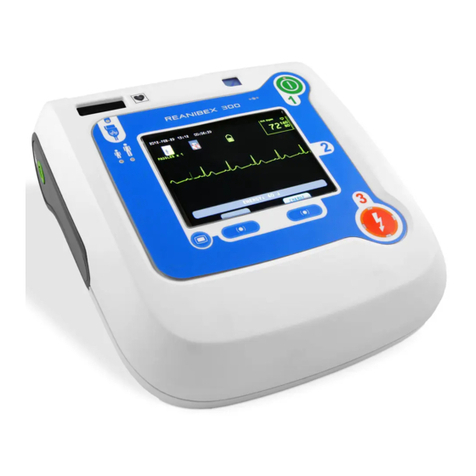
Bexen Reanibex 700 User manual


REANIBEX Serie 700
Technical Manual
Approved: R&D Director Revision: H
Date: December - 2011


TECHNICAL MANUAL DGG 700 B
Revision G 07/2011
All rights for this publication are reserved.
This manual may not be totally or partially reproduced, in any
way or by any means, without prior written authorisation from
OSATU S.Coop.
The information contained in this manual may be modified with
no need for previous notification by the manufacturer. If the
information given in this User Manual does not correspond to the
functioning of the unit, please contact an authorised
representative of OSATU S.Coop.
REANIBEX Serie 700
This is a product of: OSATU S.Coop
Edificio Zearrekobuelta
Subida de Areitio Nº 5
48260 Ermua (Bizkaia) – SPAIN
Tlf : +34 943 17 02 20
Fax : +34 943 17 02 27
www.osatu.com

TECHNICAL MANUAL DGG 700 B

TECHNICAL MANUAL DGG 700 B
i
CONTENTS
1.Warnings_________________________________________________________ 1
1.1Safety_______________________________________________________________ 1
1.2General _____________________________________________________________ 1
1.3Design and Fabrication ________________________________________________ 3
1.4Preventive Maintenance _______________________________________________ 4
1.5Check list ___________________________________________________________ 4
1.6Cleaning ____________________________________________________________ 6
1.6.1Sterilization of the internal paddles ___________________________________________7
1.7Storage _____________________________________________________________ 7
1.8Explosions___________________________________________________________ 8
1.9Batteries ____________________________________________________________ 8
1.10Repairs and Inspection _______________________________________________ 10
1.11Recycling___________________________________________________________ 10
1.12REANIBEX 700 Series Symbols________________________________________ 11
1.13On-screen symbols ___________________________________________________ 13
1.14Battery symbols _____________________________________________________ 16
1.15Unit labels __________________________________________________________ 16
1.16Battery labels _______________________________________________________ 18
2.General description________________________________________________ 19
2.1Front view__________________________________________________________ 21
2.2Upper view _________________________________________________________ 22
2.3Rear view __________________________________________________________ 24
2.4Front panel _________________________________________________________ 25
2.4.1Monitor Mode __________________________________________________________26
2.4.2Defibrillator Mode_______________________________________________________26
2.4.3Pacemaker Mode (Optional)_______________________________________________28
2.5Screen _____________________________________________________________ 28
2.6Paddles, electrodes and patient cable____________________________________ 29
3.Technical specifications ____________________________________________ 33
3.1General ____________________________________________________________ 33
3.2Defibrillation waveform ______________________________________________ 42
3.3Rhythms Detector ___________________________________________________ 47
4.General Block Diagram ____________________________________________ 50
5.Connections Diagram______________________________________________ 52

TECHNICAL MANUAL DGG 700 B
ii
6.CPU Board ______________________________________________________ 54
6.1Block Diagram ______________________________________________________ 54
6.2Description _________________________________________________________ 54
6.2.1Control________________________________________________________________55
6.2.2Patient monitor _________________________________________________________56
6.2.3Coprocessor (Optional) ___________________________________________________59
6.3Location of Components ______________________________________________ 60
6.4List of Materials_____________________________________________________ 63
7.High Voltage Board (HV)___________________________________________ 78
7.1Block diagram ______________________________________________________ 78
7.2Description _________________________________________________________ 78
7.2.1Charge and Discharge Process______________________________________________79
7.2.2Power Supply Distribution and battery charger_________________________________80
7.3Location of Components ______________________________________________ 81
7.4List of Materials_____________________________________________________ 83
8.Pacemaker Board (Optional) ________________________________________ 94
8.1Block diagram ______________________________________________________ 94
8.2Description _________________________________________________________ 94
8.3Location of Components ______________________________________________ 96
8.4List of Materials_____________________________________________________ 98
9.Display Board ___________________________________________________ 104
9.1Block diagram _____________________________________________________ 104
9.2Description ________________________________________________________ 104
9.3Location of Components _____________________________________________ 105
9.4List of Materials____________________________________________________ 106
10.Printer Support Board___________________________________________ 108
10.1Block diagram _____________________________________________________ 108
10.2Description ________________________________________________________ 108
10.3Location of Components _____________________________________________ 109
10.4List of Materials____________________________________________________ 110
11.Supplies Filter Board____________________________________________ 112
11.1Block diagram _____________________________________________________ 112
11.2Description ________________________________________________________ 112
11.3Location of Components _____________________________________________ 113
11.4List of Materials____________________________________________________ 114
12.Unit Self-Testing _______________________________________________ 116
12.1Description of the self-checks _________________________________________ 117
12.2Hardware Test _____________________________________________________ 120

TECHNICAL MANUAL DGG 700 B
iii
12.3Accessories Test ____________________________________________________ 122
12.4Front Panel Test____________________________________________________ 124
12.5Paddles Interface Test _______________________________________________ 125
13.Troubleshooting________________________________________________ 126
13.1Error Codes _______________________________________________________ 127
13.2Tests _____________________________________________________________ 129
13.3Actions to be Performed _____________________________________________ 138
13.4Problems Summary Table ___________________________________________ 139
A.1 Manufacturer’s guide and declaration of Electromagnetic Compatibility____ 147
A.3 Procedures for Changing Components _______________________________ 155
A.4 Assembly Diagrams_______________________________________________ 157

TECHNICAL MANUAL DGG 700 B
iv
Blank page

TECHNICAL MANUAL DGG 700 B
1
1. Warnings
1.1 Safety
This symbol indicates the need to read the user’s manual since pertinent
information relating to the operation of the equipment is to be found in said
manual.
Read the user manual carefully before using the unit
Keep the user manual next to the unit, in order to refer to it whenever necessary.
1.2 General
•The equipment must be used only by suitably qualified personnel.
•Remove clothing from the patient’s chest, and, if necessary, dry the patient’s chest and
shave off excess hair in the areas where the paddles or electrodes, both for defibrillation and
monitoring are to be placed. Avoid cutting the skin. Do not apply alcohol or any other
substance to the patient’s skin.
•Before defibrillating, remove any equipment connected to the patient that is not protected
against defibrillation.
•Make sure that no one is in contact with the patient when defibrillating.
•The defibrillation electrodes must never be in open circuit or short circuit during the shock.
They should be kept away from other electrodes or metallic parts that may be in contact
with the patient.
•Avoid any contact between any part of the patient’s body, such as the exposed skin of the
head and limbs, and metal objects such as the bed or stretcher frame, that could cause
undesirable deviation of the defibrillation current.
•Install the unit in a position not exposed to contact with water.

TECHNICAL MANUAL DGG 700 B
2
•Install the unit in a position where it is not negatively affected by atmospheric pressure,
temperature, damp, ventilation, sunlight and air that contains particles dust, salt, sulphur
components or other particles.
•The unit should be kept in a stable position, and any sudden movements, vibrations, blows
or any other destabilising factor should be avoided.
•Do not touch, press or scratch the screen of the device with hard objects as they may
damage it.
•Keep the apparatus clean. Clean with a damp cloth and a neutral detergent. Take account of
the directions in this manual for cleaning of the different parts of the unit.
DANGER OF FIRE OR SHOCK: Do not submerge the unit or any part of the unit in water
or other liquids. If the unit is accidentally submerged in water or other liquids, remove the
battery until it is operative again.
DANGER OF FIRE OR SHOCK: Make sure accessories and all the equipment are correctly
connected. Equipment or accessories not correctly interconnected can be a source of ignition,
or cause shock.
CAUTION: The unit can be damaged by mechanical or physical misuse, such as immersion
in water, or drops of more than 1 metre.
CAUTION: The components of the unit can be damaged if they are placed near sources of
vibration.
WARNING: Risk of dangerous electrical shock or fire. Do not immerse either the unit or any
part of it in water or any other liquid. Avoid spilling liquids on the unit or on its accessories.
Do not clean the unit with inflammable agents such as acetones. Do not sterilize the
equipment in autoclave nor in any other way.
WARNING: Dangerous electrical discharge. The equipment must be used only by authorized
personnel, by a doctor or medical director, and that has minimal training in the following
areas:
-Cardio-pulmonary resuscitation (CPR)
-Use of a Monitor/Defibrillator in accordance with the recommendations of the
American Heart Association - AHA or of the European Resuscitation Council -
ERC
-Use of the REANIBEX 700 Series

TECHNICAL MANUAL DGG 700 B
3
WARNING: Risk of dangerous electrical shock. The defibrillator can provide up to 200
Joules of energy during a discharge. When the discharge is taking place do not touch either
the patient or the defibrillation electrodes.
ATTENTION: During defibrillation avoid contact between parts of the patient’s body
(exposed skin of the head and limbs), and metallic objects such as the frame of the bed, which
can produce undesirable paths for the defibrillation current.
WARNING: Air cavities formed between the defibrillation electrodes and the patient’s skin
can cause burns during defibrillation. Make sure that the defibrillation electrodes are
perfectly adhered to the patient’s skin. Once adhered, if the position of the electrodes must be
changed, remove the electrodes and replace them with new ones.
WARNING: Do not allow the defibrillation electrodes or the paddles to touch each other, nor
that they touch any part of a conductive material during defibrillation. Such contact can
produce an electrical arch and burns to the patient’s skin.
WARNING: Incorrect use of the equipment can result in injury. Follow the instructions of
the User's Manual for its correct use.
DANGER: Possible danger of explosion if the equipment is used in the presence of
concentrated oxygen or inflammable anaesthetic products.
ATTENTION: The use of cables, electrodes or batteries of other manufacturers can cause
the unit to work incorrectly, and they invalidate the safety certifications. Use only the
accessories specified in this manual and that have been supplied by OSATU S. Coop.
WARNING: The presence of radio frequency (RF) emitter sources near the equipment can
cause its incorrect operation.
1.3 Design and Fabrication
The REANIBEX 200 unit meets the safety requirements laid down by the International
ElectroTechnical Commission, and is classified as Class I, internally powered equipoment, type
CF and continuous operating mode.

TECHNICAL MANUAL DGG 700 B
4
1.4 Preventive Maintenance
The aim of Preventative Maintenance is to ensure that the unit operates under safe working
conditions, and prevent potential problems. Suitably qualified personnel should carry preventive
Maintenance out at least once a year, only.
Make sure the unit is damage-free before using it. An immediate check should be carried out in
the following cases:
•The unit has suffered serious mechanical stress, for example after being dropped.
•The unit has suffered serious mechanical stress, for example after a fall.
•Liquid has fallen onto the unit.
•Anomalous operation of the unit has been detected.
•Any connector or cables showing signs of deterioration.
•The reusable paddles show any sign of deterioration or are broken.
•The unit’s malfunction indicator is blinking with a red color and on screen an error
code appears.
•The unit’s status indicator is red and on screen, when some of the operating modes are
accessed, an error message appears.
•In the upper part of the screen one of the icons that indicates that an error has been
detected in the unit’s modules appears.
•The battery shows signs of deterioration.
1.5 Check list
The checks and tests that it is recommended to perform to ensure the correct operation of the
device is listed below.

TECHNICAL MANUAL DGG 700 B
5
Serial number: Date:
Operative: Signature:
Procedure/Incident Recommended action Result
1. Visual inspection of the device
•The device is dirty
•There are cracks or damage
•Clean the device
•Contact Technical service
2. Visual inspection of accessories
•Connectors, cables or paddles
damaged or broken
•Battery damaged or leaking
•Battery discharged
•Inspection of the recorder paper
•Contact Technical service
•Replace the battery
•Charge the battery
•If there is no paper, replace the
recorder paper
3. Expiry dates
•Monitoring or defibrillation electrodes
expired
•Monitoring or defibrillation electrodes
opened
•Replace the expired electrodes
•Replace the opened electrodes
4. Supply
•Connect the device to an external
VAC source and check the indicator
•Connect the device to an external
VDC source and check the indicator
•If the indicator does not light up,
contact Technical service
•If the indicator does not light up,
contact Technical service
5. Integrity of the device
•Run the test Hardware
•Run the Accessories Test
•Run the Front Panel Test
•Run the Paddles Interface Test
•If any error exists contact
Technical service
•If any error exists contact
Technical service
•If any error exists contact
Technical service
•If any error exists contact
Technical service

TECHNICAL MANUAL DGG 700 B
6
1.6 Cleaning
To clean the REANIBEX Serie 700 device, the cables and the reusable external paddles the
following considerations must be taken into account:
•Use a slightly damp soft cloth. Do not use abrasive or inflammable cleaning products.
•Do not immerse the device in liquids.
•Clean the device with the batteries installed to prevent the fluids from penetrating into
the battery contacts.
•Use only the following products:
-Isopropyl alcohol
-Ammonia-based cleaning products
-Common cleaning products
-Hydrogen peroxide
-Soapy water
WARNING: Do not immerse the device or any part of it in water or in any other fluid. Do not
use abrasive or inflammable cleaning agents.
WARNING: Do not sterilize the REANIBEX Serie 700, or its accessories, in autoclave or
with gas, unless it is specified to the contrary in the instructions for use of the accessory.
WARNING: Clean and dry well the reusable external paddles after every use. The
defibrillation gel (damp or dry) accumulated both in the handles and in its containers can
interfere in monitoring with the paddles and cause shock to the user.
If the quality of printing of the recorder is not adequate the recording head must be cleaned. For
cleaning, perform the following steps:
1. Open the cover of the device under which the recorder is located
2. Open the door of the recorder pressing its safety catch
3. Extract the roll of paper.
4. Clean the printing head, above the brush, with cotton moistened in isopropyl
alcohol.
5. Position the roll of paper again and close the door of the recorder and the cover
of the device.

TECHNICAL MANUAL DGG 700 B
7
1.6.1 Sterilization of the internal paddles
In this section the steam sterilization process of the internal paddles is described. Continue the
instructions provided when carrying out this process.
1. Clean the surface of the electrodes and the handles with a standard hospitable
solution, such as, for example, isopropyl alcohol, using a soft cloth. Do not use
acetone or ammonia-based cleaners.
2. Do not put the connector into the cleaning solution.
3. Before sterilization remove any excessive residue accumulated on the surface of
the electrodes or on the handles.
4. Carry out the sterilization in a gravity sterilizer using the following parameters:
-Sterilization temperature: 121 ºC
-Duration of sterilization: 30 minutes
5. Protect the paddles before and after cleaning to avoid damaging their surface.
The shelf life of the internal paddles is affected by the number of sterilization cycles. The
internal paddles supplied by OSATU have been proven to last almost for 50 steam sterilization
cycles carried out with the previous parameters.
1.7 Storage
When the REANIBEX Serie 700 is not being used, follow the recommendations herein below
for storage of the device:
-Store the REANIBEX Serie 700 with the NiMH battery pack installed at
temperatures between 0 ºC and 40 ºC.
-Store the REANIBEX Serie 700 without the NiMH battery pack installed at
temperatures between -20 ºC and 60 ºC.
If the device is operating outside of the recommended operating or storage temperature, the
malfunction indicator located in the device front panel will remain switched on until the
ambient temperature is within the stated range.

TECHNICAL MANUAL DGG 700 B
8
1.8 Explosions
This unit has not been designed to be explosion-proof, and therefore it must not be used in
rooms or environments where there is a risk of explosion, nor in the presence of inflammable
anaesthetic products nor concentrated oxygen.
FIRE OR EXPLOSION HAZARD: Do not use the unit when inflammable or anaesthetic
gases are present.
1.9 Batteries
In this section the considerations to be taken into account for correct battery maintenance are
explained, as well as the process for changing it. Good battery maintenance optimizes its
duration, and guarantees that the that the device provides accurate indication about battery
charge.
The REANIBEX Serie 700 uses high capacity rechargeable NiMH batteries that require
minimal maintenance. The duration of a rechargeable NiMH battery depends on its frequency
and use. When used and maintained correctly the useful life of the battery is 5years or 500
charge/shock cycles.
Adequate maintenance of the battery implies taking the following considerations into account:
•Store the battery at temperatures less than 30 ºC and never expose the battery to high
temperatures, greater than 40 ºC.
•Periodically carry out complete discharges of the battery (it is recommended once a
month), for this purpose switching the device on without connecting it to any external
power supply, until the battery condition indicator lights up with a red color.
•If the battery of the device is left out of it for a long period of time, and is stored at a
temperature less than 30 ºC, recharge the battery every 6 months.
ATTENTION: Use only batteries supplied by OSATU or by its authorized distributors. The
use of another battery type can cause the device not to operate correctly.

TECHNICAL MANUAL DGG 700 B
9
WARNING: Storage of the batteries at temperatures greater than 30 ºC significantly reduces
their lifespan.
When it performs self-tests at start-up and during operation, the device checks the battery
charge giving the appropriate instructions in case its charge is low.
If on switching the device on, the battery indicator located on the front panel of the device is red
in colour at start-up, it indicates that it is necessary to charge the battery, for this purpose
connecting the device to an external power supply (car battery or AC mains).
WARNING: Danger of explosion. Do not recharge the REANIBEX Serie 700 batteries
outside of the device, since they could explode.
Store the new battery packs at temperatures between 0 ºC and 35 ºC. The optimum temperature
for storage of the batteries is 25 ºC.
When the battery is stored under ideal conditions, its capacity is equivalent to more than 130
discharges of 200 J, or more than 150 minutes of monitoring, or more than 120 minutes of
monitoring plus pacemaker stimulation at 60 mA and 60 bpm.
Changing of the device external battery is shown in the following drawing:
When the batteries are installed in the equipment, and this in turn is connected to an external
power supply (AC mains or car battery), the device continuously charges the battery, using an
internal charger.

TECHNICAL MANUAL DGG 700 B
10
To extract the battery, pull upwards the battery retaining device (coloured black) and supporting
it in this position extract the battery from its compartment.
If there is visible damage or if they become damaged, the NiMH batteries must be recycled.
Follow the local, regional or national instructions of your country when recycling.
WARNING: Follow the local, regional or national instructions of your country when
recycling the REANIBEX Serie 700 batteries, or send them to OSATU S. Coop.
WARNING: Danger of explosion. Do not try to open or to handle the battery. Do not
incinerate the battery. Avoid electrical contact between the battery terminals.
1.10 Repairs and Inspection
OSATU S.Coop. can only accept liability for the safety aspects of the REANIBEX 700 when
the maintenance, repairs and subsequent modifications have been carried out by our technical
personnel or by companies authorised by us, and when components affecting the safety of the
unit have been replaced with original spare parts.
The company reserves the right to carry out possible modifications without prior notice.
On request, OSATU S.Coop will provide circuit diagrams, component lists, descriptions,
calibration instructions and other information that assist the suitably qualified technical
personnel to repair those parts of the unit designated by the manufacturer as repairable.
1.11 Recycling
•The REANIBEX Serie 700 must be cleaned and disinfected before being recycled. The
device must be recycled in accordance with the recommendations of local, regional or
national authorities of each country.
•The NiMH batteries once their useful life has finished, must be recycled in accordance with
local, regional or national procedures of each country.
Table of contents
Other Bexen Medical Equipment manuals